Troubleshooting Guide
Owner
’
s Manual
ANCHOR Audio, Inc. (310) 784-2300
100-0082-000 / Revision A, 06/98
Having trouble with the sound system?
Condition Possible Solution
No sound (power LED not lit): • turn POWER switch ON
•replace fuse
No sound (power LED lights): •check for output from source
• make sure all cables are completely plugged in
• increase volume control on input used
Distorted sound: • check input cable connection
•lower input signal level
Excessive hum or noise: • use shielded input cable
• use a balanced input
Having trouble with the wireless system?
Condition Possible Solution
No sound (TX ON indicator lights): •set mute switch to ON position
•turn up wireless volume control
•plug a mic into belt-pack transmitter
No sound
(TX ON indicator off): •turn sound system ON
•turn transmitter power switch ON
•replace battery in transmitter
LIBERTY
MPA-5000

2
Important Safeguards Specifications
15
MPA-5000
rated power output:
low frequency amp: 90 watts @ 4Ω continuous
high frequency amp: 40 watts @ 16Ω continuous
max SPL @ rated power: 115 dB; 122 dB project mode “on”
General
frequency response: 80 Hz - 15 kHz;
project mode “on”: +8 dB from 2 - 12 kHz
speaker types: 8" woofer, constant-directivity horn
Bass / Treble control: 8 db cut / boost @ 100 Hz, 8 kHz
Inputs
line input: 1/4"-phone, Hi-Z, unbalanced
mic input: XLR female, Lo-Z, 15VDC phantom power
balanced input: XLR female, switchable mic/line level
15VDC phantom power (switchable)
Anchor CD input: audio & power for Anchor CD-1 CD player
sensitivity for rated output:
unbalanced line: -18 dBV (125 mVrms)
balanced mic: -58 dBV (1.25 mVrms)
balanced input:
mic: -58 dBV (1.25 mVrms)
line: -15 dBV (175 mVrms)
Outputs
Line Output (post fader): XLR male, 600Ω, active balanced
DC Output: 12 Volts DC, 300 ma max.
AC power requirements: 110 - 125 VAC, 50/60 Hz
export model: 210 - 240 VAC, 50/60 Hz
(250 watts maximum, 30 watts idle)
AC accessory outlet: 110 - 125 VAC, 50/60 Hz
export model: 210 - 240 VAC, 50/60 Hz
(500 watts maximum)
fuse rating: T 3.15A / 250V
export model: T 1.6A / 250V
dimensions (HWD): 22.5 x 13 x 10", 57 x 33 x 26 cm
weight: 35 pounds, 16 Kg.
Specifications subject to change without notice.
CAUTION: To reduce the risk of electric shock, do not remove the cover.
No user-serviceable parts inside. Refer servicing to qualified personnel.
WARNING: To prevent fire or electric shock, do not expose this equipment
to rain or moisture.
CAUTION: To reduce the risk of fire, replace only with same type fuse (see
specifications).
ATTENTION: Pour eviter les risques de choc électrique, ne pas enlever le
couvercle. Aucun entretien de pièces intérieures par l'usager. Confier
l'entretien au personnel qualifié.
AVIS: Pour eviter les risques d'incendie ou d’électrocution, n'exposez pas
cet article à la pluie ou a l'humidité.
ATTENTION: Pour diminuer le risque d’incendie, remplacer par des fusibles
de même type (voir caractéristiques).
EXPLANATION OF GRAPHICAL SYMBOLS
The lightning flash with arrowhead symbol, within an equilateral triangle, is
intended to alert the user to the presence of uninsulated “dangerous
voltage” within the product’s enclosure that may be of sufficient
magnitude to constitute a risk of electric shock to humans.
The exclamation point, within an equilateral triangle, is intended to alert
the user to the presence of important operating and maintenance
(servicing) instructions in the literature accompanying the appliance.
EXPLICATION DES SYMBOLES GRAPHIQUES
Le symbole éclair avec point de flèche à l'intérieur d'un triangle équilatéral
est utilisé pour alerter l'utilisateur de la presence à l'intérieur du coffret de
“voltage dangereux” non isolé d'ampleur suffisante pour constituer un
risque d'elétrocution.
Le point d'exclamation à l'intérieur d'un triangle équilatéral est employé
pour alerter les utilisateurs de la présence d'instructions importantes pour
la fonctionnement et l'entretien (service) dans le livret d'instruction
accompagnant l'appareil.
DATE OF MANUFACTURE
The date of manufacture can be determined by the seven digit serial
number code. The first digit denotes the month (A=Jan, B=Feb, etc.), and
the second and third digits denote the year. Example: " B980033"
indicates the unit was manufactured in February of 1998.
RISK OF ELECTRIC SHOCK
DO NOT OPEN
CAUTION
RISQUE DE CHOC
ELECTRIQUE
NE PAS OUVRIR
AVIS

Quick Use Guide
Liberty Xtreme is an AC-powered sound system optimized for
applications requiring very loud, clear sound. It has several
signal input options, and a line output to connect with other
systems. The speech project feature makes it ideal for both
music or speech applications, indoors or out.
You’ll need a microphone or some other input source before
you get started.
Here’s how easy it is to use
1. Set the unit in front of your audience on the floor,
table or on a speaker stand.
2. Plug a microphone into a balanced mic input XLR
jack, or plug an audio source into a line input.
3. Set all input level controls to minimum, and set bass
and treble to the 12:00 position.
4. Plug the power cord in, then turn the power switch ON.
Slowly increase the level control adjacent to the input
used until desired volume is reached.
5. For music and indoor applications, set the speech
project switch to OFF.
For speech and outdoor applications, set the speech
project switch to ON.
6. Adjust the bass and treble for desired sound quality.
To operate the wireless mic system on wireless models, see
“Wireless Operation” on pages 11 and 12. And for more detailed
instructions, see the “Operation” section beginning on page 8.
Problems?
Consult the
troubleshootin
g section on
the back page
of this manual.
Thank you for choosing an Anchor Audio portable sound system. Our products
incorporate state-of-the-art design and the finest quality of materials and
workmanship. We’re proud of our products and appreciate the confidence which
you have shown by selecting an Anchor system.
I hope you’ll take a few of minutes to review this manual. We’ve incorporated
several unique features into our products, and your knowledge of how to use
them will enhance the performance and your enjoyment of the system.
David Jacobs, President on behalf of all Anchor employees
14
Blank Page
3

13
MIC-90 Handheld Microphone
Anchor’s dynamic, balanced, low impedance microphone
with a unidirectional pick-up pattern. It has an on/off switch
and comes with a 20' cable and mic clip.
SS-450 Speaker Stand
Made of heavy duty structural aluminum.
VL-45 Storage Cover
Heady duty cover for Liberty.
EX-50M Microphone Cable
50' mic extension cable.
MSB-201 Microphone Stand and Boom
Microphone floor stand with 33" adjustable boom.
FL-4500 Admiral Lectern
Floor model lectern with a center console to accommodate a
Liberty sound system. It has a shock-mounted mic input.
PWRADPTR AC Power Cord Adapter
Liberty Xtreme AC outlet to standard USA 3-prong female
receptacle—allows use of standard extension cable.
PWRCORD-50 AC Power Cord
50' AC power cord for accessory outlet; IEC-320 connectors
on both ends (male to female).
CD-1 Portable CD Player
Portable CD player module mounted on speaker stand with
microphone tray/holder and cable.
EX-50PP Line Cable
50' shielded line cable; 1/4"-phone connectors on each end.
EX-50XFP Line Cable
50' shielded line cable; XLR female to 1/4"-phone connectors.
DCM Wireless System Interconnect Cable
Connects DC power from sound system to receiver and
audio output from receiver to input of sound system.
AccessoriesGetting Started
4
Inspection and inventory of your system
Check unit carefully for damage which may have occurred
during transit. Each Anchor product is carefully inspected at
the factory and packed in a special carton for safe transport.
Inventory
• Liberty Xtreme sound system
• Warranty registration card
• Wireless mic/transmitter (with wireless option only)
All damage claims must be made with the freight carrier.
Notify the freight carrier immediately if you observe any
damage to the shipping carton or product. Repack the unit
in the carton and await inspection by the carrier’s claim agent.
Notify your dealer of the pending freight claim.
Returning your unit for service or repairs
Should your unit require service, contact your dealer or our
Customer Service Department at (310) 784-2300 to obtain a
Return Authorization (RA) number. All shipments to Anchor
must include an RA number and must be shipped prepaid.
C.O.D. shipments will be refused and returned at your cost.
Warranty registration
Please fill out the warranty card and return it with a copy of
your invoice to Anchor’s Customer Service Department. This
will activate your limited two year warranty.
Save the
shipping
carton and
packing
materials. They
were specially
designed to
ship your unit
safely.

12
Wireless Operation
Replacing the transmitter battery
Note: The transmitter power switch must be in the OFF position!
HANDHELD: Unscrew the battery compartment cover on
the lower end of microphone. Install a fresh 9 Volt alkaline
battery* and replace the cover.
BODY-PACK: Press the “OPEN” end of the battery cover,
slide it back and lift the cover. Install a fresh 9 Volt alkaline
battery* b
eing sure to observe proper polarity. Close the cover.
Operating the wireless microphone system
The audio signal from the built-in wireless receiver is fed into
the mixing bus. The wireless mic may be used simultaneously
with any of the other inputs .
Operating the wireless microphone system:
1. Set the wireless volume control to minimum.
2. Turn the sound system power switch ON.
3. Slide the transmitter power switch to PWR.
The sound system’s TX ON indicator
lights to indicate wireless signal (RF)
is being transmitted and received.
4. Adjust the wireless control to desired volume.
Caution: Harmful feedback may occur when walking in front of a
sound system or speaker with a wireless microphone. Always point
mic away from speakers.
Using the microphone ON/MUTE switch:
When set to the “ON” position the mic operates normally.
To prevent unwanted sounds from being picked up without
turning the transmitter off, move switch to “MUTE” position.
(The handheld mic/transmitter comes with a protective
sleeve which fits over the power and mute switches to prevent
accidental movement during use. To install it, unscrew the
battery cover and slide the sleeve onto the microphone handle.
Replace the cover.)
WIRELESS
MIC VOLUME
TX ON
CA
ON
MUTE
*Duracell
MN1604 or
equivalent.
Feedback Information
5
What causes feedback?
Feedback is a ringing, howling, or shrill sound that is self-
generated by the sound system. It is the result of sound from
the speakers being picked up by the microphone and then
re
-
amplified by the system. This can form a self-sustaining
loop that can damage the sound system if allowed to continue.
How to prevent feedback
ALWAYS STAND BEHIND THE SPEAKER
WHEN USING A MICROPHONE!
CAUTION: Feedback can damage your equipment and may be
hazardous to your hearing. To avoid feedback, always make
sure volume controls are at minimum before turning unit on.
If feedback occurs, immediately reduce the volume.

11
Wireless Operation
Setting up the wireless system
Checking the Frequency Code:
Before proceeding, you must first verify that the wireless
frequency of your transmitter matches the frequency of the
receiver installed in your Anchor sound system.
1. The control panel of the sound system should have
the following label:
2. The frequency code must match the code found on
the transmitter as described below:
HANDHELD: Unscrew the battery compartment
cover on lower end of the microphone. Remove the
battery (if installed) and check code on the label.
BODY-PACK: Check the code on the label located
behind the belt clip.
3. If the frequency codes don’t match, locate the correct
transmitter whose code matches the sound system.
About the transmitter battery gauge/indicator
Assuming a battery is installed in the transmitter, you can
estimate the remaining operating time by sliding the power
switch to the PWR position (first turn the sound system off,
or set the transmitter mute switch to the MUTE position).
Observe the color of the LED indicator(s) that light up:
Battery LED Indicator Operating Time
green 6 - 20 hours
green & amber 4 - 6 hours
amber 2 - 4 hours
red< 1 hour
TX ON
CA
Frequency Code label
(Shure designates a one- or two-letter code
which corresponds to the wireless frequency
at which the component operates.)
SHURE BROTHERS INC.
LX2 HANDHELD TRANSMITTER
FREQUENCY CODE –
CA
176.200 MHz
SHURE BROTHERS INC.
TX FCC ID: DD4L11
CANADA: 616 C9398
LX1 –
CA 176.200 MHz
label on handheld mic/transmitter
label on body-pack transmitter
Operating times
using a fresh
9 volt alkaline
battery
*Duracell
MN1604 or
equivalent.
Now Featuring
WIRELESS
6
Setting up the Liberty Xtreme sound system
Positioning of the speaker is perhaps the most important
consideration when setting up a sound system. You should
survey the location prior to the activity and observe the
seating arrangement and area of coverage.
Basic principles of sound system set up:
•Position your sound system in front of the audience
and ahead of the microphone.
• Elevate the sound system so the sound projects over
the front listeners. This permits sound to reach the
listeners in the rear without overpowering those in
front. The Liberty is easily and safely elevated above
the audience by using Anchor’s SS-450 speaker stand.
•For long and narrow seating arrangements, position
one sound system in front and off to one side of the
listeners. Then position a second sound system mid-
way back on the same side of the audience. Direct the
speakers diagonally across the audience (see notes
regarding daisy-chaining below).
• Daisy Chain operation: There may be times when the
crowd size requires more than one sound system, or
when part of the audience is in a separate listening
area. To use multiple Liberty Xtreme systems, connect
a shielded mic cable between the Line Output of the
primary sound system to the Balanced Line Input of
Set-Up
sound system
sound systemsound system
Keep in mind,
the best sound
system set-up is
when the
audience is not
conscious of a
sound system
being used.

10
Speech Project Switch
The speech project switch allows the user to customize the
sound output of the Liberty Xtreme for a particular
application:
Standard setting (button out):
Liberty Xtreme provides flat, full-range frequency response
for music/singing or indoor vocal applications.
Speech Project setting (button in):
Frequencies in the vocal range (800Hz-12KHz) are boosted
for added clarity and efficient projection. Use for outdoor
functions, large crowds and speech applications.
12 Volt DC Output
The DC output jack is used to power
auxiliary equipment such as an outboard
wireless receiver or Anchor’s Mini-Mix.
It’s rated output is 12 volts DC, 300 ma
maximum.
Using the cassette tape player
The cassette player features auto reverse for continuous
playback. The audio signal is fed directly into the mixing bus
so the sound can be mixed with other inputs of the Liberty.
Note: Use only high-quality tapes, and periodically clean the tape
head with a cleaning kit.
Operation Set-Up
the second system. Set the volume on the second
system, and thereafter the volume of the primary
Liberty Xtreme will control both units.
Setting up difficult rooms
Reverberant rooms—those with acoustically-reflective
surfaces like glass or concrete (such as a gymnasium), can be
troublesome when using a sound system. Proper care must
be used during setup to minimize feedback, which is caused
by the microphone ‘hearing’ the sound reflected back from
the walls, floors and ceilings.
Te c hniques to reduce feedback in difficult rooms:
•The best microphones to use in feedback-prone rooms
are handheld, CollarMic
™
or headset boom types. They
allow the mic element to be close to the mouth so the
system ‘sees’ more of the user’s voice and less of the
room. The volume control can be turned down while
still maintaining an adequate sound level—another
important factor in reducing feedback.
•Orienting the speakers directly at the crowd and away
from the walls (and the user, or course) will help
reduce feedback. Experimentation may be necessary.
second systemprimary system
third system
A lapel mic will
perform poorly
under these
conditions and
should not be
considered.
7
12 VDC Out
(300 ma MAX)
+12 VDC
AUTO REVERSE CASSETTE
EJECT
TAPE
VOLUME
To change tracks
(sides), push
button half-way in.
To eject tape, push
button fully in.
off on
To control
feedback, try
attenuating the
bass or treble
control.

9
Operation
Line Input
The unbalanced line input is used for playback of a tape or
CD player, musical instrument, VCR or similar line-level
source. It may be combined with the other inputs for a
composite output.
N
ote:
All audio connections must be made with shielded cable
to avoid hum, buzzing or radio interference.
Mic Input
The balanced, low impedance XLR microphone input is for
use with a balanced microphone to help prevent hum or
interference when using long cables. It has phantom power
for use with condenser-type microphones.
Balanced Input
Liberty Xtreme is equipped with a balanced XLR input jack
that can be set to allow microphone or line level sources, with
or without phantom power (15 volts DC).
A balanced microphone (Lo-Z) is preferred for use with long
cables to minimize hum and interference. Phantom power is
required when using mics with a condenser element; in all
other cases the phantom power switch should be set to OFF.
Anchor CD Input
The Anchor CD input provides an audio and power
connection for the CD-1 CD player accessory.
Line Output
The line output provides a balanced, composite signal of
the inputs being used. Use the line output to record your
presentation, or to “daisy chain” another powered sound
system to the Liberty Xtreme for greater crowd coverage.
Accessory Outlet
Use the Xtreme 5000’s accessory outlet to supply AC power
to an additional sound system or accessory. Anchor’s
PWRADPTR or PWRCORD cables allow easy connection
when running extension cables.
Line In
cd
tape
Balanced
Input
xtreme
mixer
microphone
line mic
off on
input level
phantom power
Anchor
CD
Input
Accessory
Outlet
Balanced
Line Out
Mic In
Fuse
PWR
on
off
Balanced
Line Out
12 VDC Out
(300 ma MAX)
Balanced
Input
xtreme
mixer
microphone
Mic In
Line In
cd
tape
Anchor
CD
Input
Speech Project
Accessory
Outlet
line mic
off on
off on
input level
phantom power
bass treble
LIBERTY
MPA-5000
8
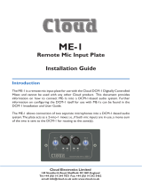
Operation
Line Output
(XLR jack)
Line Input
(1/4" phone jack)
Phantom Power
Switch
Balanced Input
(XLR jack)
Input Level Switch
Fuse
Power Switch
AC Accessory
Outlet
Power Indicator
Liberty Xtreme 5000 control panel
Operating the sound system
1. Set all input level controls to minimum, and set bass
and treble to 12:00 position before turning power on.
2. Plug a microphone into a balanced mic input XLR
jack, or plug an audio source into a line input.
3. Turn power ON (red LED above switch will light).
4. Adjust level control adjacent to the input jack used to
the desired volume level.
5. Adjust the bass and treble controls (and speech
project switch, if necessary) for desired sound.
Mic Input
(XLR jack)
Anchor CD Input
(4-pin XLR jack)
AC Power Cord
Receptacle
Input Level ControlsSpeech Project Switch
DC Output
Bass and Treble
Controls
/