Supermicro SUPERO SUPERSERVER 1028R-WTR Series User manual
- Category
- Server barebones
- Type
- User manual
This manual is also suitable for

SUPERSERVER
®
1028R-WTR(T)
®
SUPER
USER’S MANUAL
Revision 1.0

The information in this User’s Manual has been carefully reviewed and is believed to be accurate.
The vendor assumes no responsibility for any inaccuracies that may be contained in this document,
makes no commitment to update or to keep current the information in this manual, or to notify any
person or organization of the updates. Please Note: For the most up-to-date version of this
manual, please see our web site at
www.supermicro.com.
Super Micro Computer, Inc. ("Supermicro") reserves the right to make changes to the product
described in this manual at any time and without notice. This product, including software and
documentation, is the property of Supermicro and/or its licensors, and is supplied only under a
license. Any use or reproduction of this product is not allowed, except as expressly permitted by
the terms of said license.
IN NO EVENT WILL SUPERMICRO BE LIABLE FOR DIRECT, INDIRECT, SPECIAL, INCIDENTAL,
SPECULATIVE OR CONSEQUENTIAL DAMAGES ARISING FROM THE USE OR INABILITY TO
USE THIS PRODUCT OR DOCUMENTATION, EVEN IF ADVISED OF THE POSSIBILITY OF
SUCH DAMAGES. IN PARTICULAR, SUPERMICRO SHALL NOT HAVE LIABILITY FOR ANY
HARDWARE, SOFTWARE, OR DATA STORED OR USED WITH THE PRODUCT, INCLUDING THE
COSTS OF REPAIRING, REPLACING, INTEGRATING, INSTALLING OR RECOVERING SUCH
HARDWARE, SOFTWARE, OR DATA.
Any disputes arising between manufacturer and customer shall be governed by the laws of Santa
Clara County in the State of California, USA. The State of California, County of Santa Clara shall
be the exclusive venue for the resolution of any such disputes. Super Micro's total liability for all
claims will not exceed the price paid for the hardware product.
FCC Statement: This equipment has been tested and found to comply with the limits for a Class
A digital device pursuant to Part 15 of the FCC Rules. These limits are designed to provide
reasonable protection against harmful interference when the equipment is operated in a commercial
environment. This equipment generates, uses, and can radiate radio frequency energy and, if not
installed and used in accordance with the manufacturer’s instruction manual, may cause harmful
interference with radio communications. Operation of this equipment in a residential area is likely
to cause harmful interference, in which case you will be required to correct the interference at your
own expense.
California Best Management Practices Regulations for Perchlorate Materials: This Perchlorate
warning applies only to products containing CR (Manganese Dioxide) Lithium coin cells. “Perchlorate
Material-special handling may apply. See
www.dtsc.ca.gov/hazardouswaste/perchlorate”
WARNING: Handling of lead solder materials used in this
product may expose you to lead, a chemical known to
the State of California to cause birth defects and other
reproductive harm.
Manual Revision 1.0
Release Date: August 14, 2014
Unless you request and receive written permission from Super Micro Computer, Inc., you may not
copy any part of this document.
Information in this document is subject to change without notice. Other products and companies
referred to herein are trademarks or registered trademarks of their respective companies or mark
holders.
Copyright © 2014 by Super Micro Computer, Inc.
All rights reserved.
Printed in the United States of America

iii
Preface
Preface
About This Manual
This manual is written for professional system integrators and PC technicians. It
provides information for the installation and use of the SuperServer 1028R-WTR(T).
Installation and maintainance should be performed by experienced technicians only.
The SuperServer 1028R-WTR(T) is a high-end server based on the
SC116TS-R706WBP 1U rackmountable chassis and the X10DRW-i(T) dual
processor serverboard.
The only difference between the 1028R-WTR and 1028R-WTRT servers is that
the 1028R-WTR use 1Gps dual LAN ports and the 1028R-WTRT uses 10Gps dual
LAN ports.
Manual Organization
Chapter 1: Introduction
The fi rst chapter provides a checklist of the main components included with the
server system and describes the main features of the X10DRW-i(T) serverboard
and the SC116TS-R706WBP chassis.
Chapter 2: Server Installation
This chapter describes the steps necessary to install the SuperServer 1028R-WTR(T)
into a rack and check out the server confi guration prior to powering up the system.
If your server was ordered without processor and memory components, this chapter
will refer you to the appropriate sections of the manual for their installation.
Chapter 3: System Interface
Refer here for details on the system interface, which includes the functions and
information provided by the control panel on the chassis as well as other LEDs
located throughout the system.
Chapter 4: System Safety
You should thoroughly familiarize yourself with this chapter for a general overview
of safety precautions that should be followed when installing and servicing the
SuperServer 1028R-WTR(T).
Chapter 5: Advanced Serverboard Setup
Chapter 5 provides detailed information on the X10DRW-i(T) serverboard,
including the locations and functions of connections, headers and jumpers. Refer
to this chapter when adding or removing processors or main memory and when
reconfi guring the serverboard.

SUPERSERVER 1028R-WTR(T) USER'S MANUAL
iv
Chapter 6: Advanced Chassis Setup
Refer to Chapter 6 for detailed information on the SC116TS-R706WBP server
chassis. You should follow the procedures given in this chapter when installing,
removing or reconfi guring drives and when replacing system power supply units
and cooling fans.
Chapter 7: BIOS
The BIOS chapter includes an introduction to BIOS and provides detailed information
on running the CMOS Setup Utility.
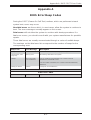
Appendix A: BIOS Error Beep Codes
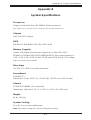
Appendix B: System Specifi cations

Notes
Preface
v

vi
Table of Contents
Chapter 1 Introduction
1-1 Overview .........................................................................................................1-1
1-2 Serverboard Features .....................................................................................1-2
Processors ...................................................................................................... 1-2
Memory ........................................................................................................... 1-2
Serial ATA ........................................................................................................1-2
PCI Expansion Slots .......................................................................................1-3
Rear I/O Ports .................................................................................................1-3
1-3 Server Chassis Features ................................................................................ 1-3
System Power .................................................................................................1-3
Hard Drive Subsystem ....................................................................................1-3
Front Control Panel .........................................................................................1-3
Cooling System ...............................................................................................1-4
1-6 Advanced Power Management ....................................................................... 1-4
Intel® Intelligent Power Node Manager (IPNM) ............................................. 1-4
Manageability Engine (ME) ............................................................................. 1-4
1-4 Contacting Supermicro ....................................................................................1-6
Chapter 2 Server Installation
2-1 Overview .........................................................................................................2-1
2-2 Unpacking the System ....................................................................................2-1
2-3 Preparing for Setup .........................................................................................2-1
Choosing a Setup Location ............................................................................. 2-1
2-4 Warnings and Cautions ...................................................................................2-2
Rack Precautions ............................................................................................2-2
Server Precautions .......................................................................................... 2-2
Rack Mounting Considerations ....................................................................... 2-3
Ambient Operating Temperature ................................................................2-3
Reduced Airfl ow .........................................................................................2-3
Mechanical Loading ................................................................................... 2-3
Circuit Overloading .....................................................................................2-3
Reliable Ground .........................................................................................2-3
2-5 Rack Mounting Instructions ............................................................................. 2-4
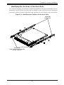
Identifying the Sections of the Rack Rails ...................................................... 2-5
SUPERSERVER 1028R-WTR(T) USER'S MANUAL

vii
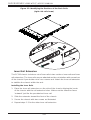
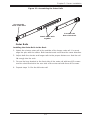
Inner Rail Extension ........................................................................................2-6
Outer Rails ...................................................................................................... 2-7
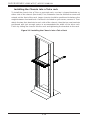
Installing the Chassis into a Telco rack ........................................................ 2-10
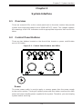
Chapter 3 System Interface
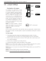
3-1 Overview .........................................................................................................3-1
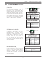
3-2 Control Panel Buttons .....................................................................................3-1
Power ..............................................................................................................3-1
UID ..................................................................................................................3-2
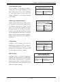
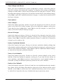
3-3 Control Panel LEDs ........................................................................................ 3-2
Universal Information LED ..............................................................................3-2
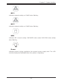
NIC1 ................................................................................................................3-3
NIC2 ................................................................................................................3-3
HDD .................................................................................................................3-3
Power ..............................................................................................................3-3
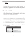
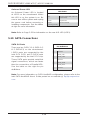
3-4 Hard Drive Carrier LEDs .................................................................................3-4
SATA Drives .................................................................................................... 3-4
Chapter 4 Standardized Warning Statements for AC Systems
4-1 About Standardized Warning Statements ....................................................... 4-1
Warning Defi nition ........................................................................................... 4-1
Installation Instructions ....................................................................................4-4
Circuit Breaker ................................................................................................4-5
Power Disconnection Warning ........................................................................4-6
Equipment Installation .....................................................................................4-8
Restricted Area ................................................................................................4-9
Battery Handling ............................................................................................4-10
Redundant Power Supplies .......................................................................... 4-12
Backplane Voltage ........................................................................................ 4-13
Comply with Local and National Electrical Codes ........................................4-14
Product Disposal ...........................................................................................4-15
Hot Swap Fan Warning .................................................................................4-16
Power Cable and AC Adapter ...................................................................... 4-18
Table of Contents

viii
SUPERSERVER 1028R-WTR(T) USER'S MANUAL
Chapter 5 Advanced Serverboard Setup
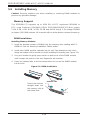
5-1 Handling the Serverboard ...............................................................................5-1
Precautions ..................................................................................................... 5-1
Unpacking ....................................................................................................... 5-1
5-2 Connecting Cables ..........................................................................................5-2
Connecting Data Cables .................................................................................5-2
Connecting Power Cables .............................................................................. 5-2
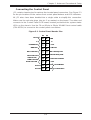
Connecting the Control Panel ......................................................................... 5-3
5-3 Rear I/O Ports .................................................................................................5-4
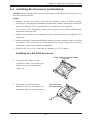
5-4 Installing the Processor and Heatsink ............................................................ 5-5
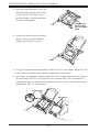
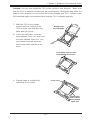
Installing an LGA 2011 Processor ................................................................... 5-5
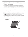
Installing and Removing a Passive CPU Heatsink .........................................5-8
5-5 Installing Memory ..........................................................................................5-10
Memory Support ............................................................................................ 5-10
DIMM Installation .......................................................................................... 5-10
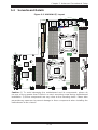
5-4 Serverboard Details ...................................................................................... 5-13
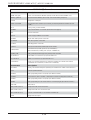
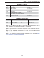
5-7 Connector Defi nitions ................................................................................... 5-16
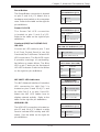
5-8 Jumper Settings ............................................................................................5-22
Explanation of Jumpers ................................................................................ 5-22
5-9 Onboard LED Indicators ............................................................................... 5-25
5-10 SATA Connections .........................................................................................5-26
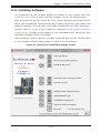
5-11 Installing Software .........................................................................................5-27
SuperDoctor 5 ...............................................................................................5-28
5-12 Serverboard Battery ......................................................................................5-30
Chapter 6
Advanced Chassis Setup
6-1 Static-Sensitive Devices ..................................................................................6-1
Precautions ..................................................................................................... 6-1
Unpacking ....................................................................................................... 6-1
6-2 Control Panel ..................................................................................................6-2
6-3 System Fans ...................................................................................................6-3
System Fan Failure .........................................................................................6-3
Checking the Airfl ow .......................................................................................6-4
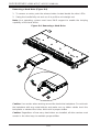
6-4 Drive Bay Installation/Removal .......................................................................6-5
Accessing the Drive Bays ...............................................................................6-5
Hard Drive Installation ..................................................................................... 6-5

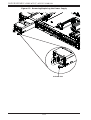
6-5 Power Supply ..................................................................................................6-7
Power Supply Failure ......................................................................................6-7
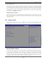
Chapter 7 BIOS
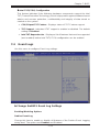
7-1 Introduction ......................................................................................................7-1
Starting BIOS Setup Utility .............................................................................. 7-1
How To Change the Confi guration Data .........................................................7-2
Starting the Setup Utility .................................................................................7-2
7-2 Main Setup ......................................................................................................7-2
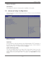
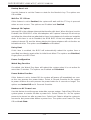
7-3 Advanced Setup Confi gurations......................................................................7-3
7-4 Event Logs ....................................................................................................7-23
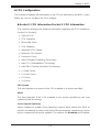
7-5 IPMI ...............................................................................................................7-25
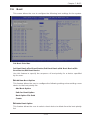
7-6 Boot ............................................................................................................... 7-27
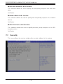
7-7 Security ......................................................................................................... 7-28
7-8 Save & Exit ................................................................................................... 7-29
Appendix A BIOS Error Beep Codes
Appendix B System Specifi cations
Table of Contents
ix

Notes
SUPERSERVER 1028R-WTR(T) USER'S MANUAL
x

Chapter 1
Introduction
1-1 Overview
The SuperServer 1028R-WTR(T) is a high-end server comprised of two main
subsystems: the SC116TS-R706WBP 1U chassis and the X10DRW-i(T) dual
processor serverboard. Please refer to our web site for information on operating
systems that have been certifi ed for use with the system (www.supermicro.com).
In addition to the serverboard and chassis, various hardware components have been
included with the SuperServer 1028R-WTR(T), as listed below:
• Heatsinks:
One Passive CPU heatsink (SNK 0057PSC or SNK-P0047PSC)
One Passive CPU heatsink (SNK-P0057PS)
• Four 4-cm PWM fans (FAN-0101L4)
• One air shroud (MCP-310-19002-0N)
• One 70-cm 20-pin to 20-pin 20-AWG front control cable (CBL-0335L)
• SATA Accessories:
One SATA backplane (BPN-SAS-116TQ)
Ten drive carriers (MCP-220-00047-0B)
One 77-cm 10-pin to 10-pin 26-AWG two-channel USB cable (CBL-0263L)
Two 29-cm 30-AWG SATA cables (CBL-0483L)
One 27-cm 8-pin to 8-pin round SGPIO cable (CBL-CDAT-0660)
One 40-cm 8-pin to 8-pin round SGPIO cable (CBL-CDAT-0661)
One 61.5-cm 28-AWG SGPIO cable (CBL-CDAT-0662)
Two 31-cm 30-AWG SATA cables (CBL-SAST-0639)
Two 38-cm 30-AWG SATA cables (CBL-SAST-0640)
Two 45-cm 30-AWG SATA cables (CBL-SAST-0641)
Two 55-cm 30-AWG SATA cables (CBL-0488L)
• One riser card (RSC-R1UW-2E16-O-P)
• One rackmount kit (MCP-290-00063-0N)
Chapter 1: Introduction
1-1

1-2
SUPERSERVER 1028R-WTR(T) USER'S MANUAL
Note: For your system to work properly, please follow the links below to download
all necessary drivers/utilities and the user’s manual for your server.
• Supermicro product manuals: http://www.supermicro.com/support/manuals/
• Product drivers and utilities: ftp://ftp.supermicro.com
• Product safety information:
http://super-dev/about/policies/safety_information.cfm
• If you have any questions, please contact our support team at:
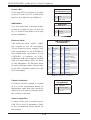
1-2 Serverboard Features
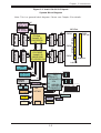
The SuperServer 1028R-WTR(T) is built around the X10DRW-i(T), a dual processor
serverboard based on the Intel PCH-C612 chipset and designed to provide
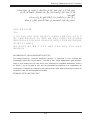
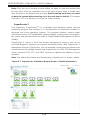
maximum performance. Below are the main features of the X10DRW-i(T),. (See
Figure 1-1 for a block diagram of the chipset.)
Processors
The X10DRW-i(T) supports single or dual Intel® Xeon E5-2600v3 Series processors
in Socket R3-LGA 2011 sockets. Please refer to the serverboard description pages
on our web site for a complete listing of supported processors (www.supermicro.
com).
Memory
The X10DRW-i(T) has sixteen (16) DIMM slots that can support up to 1024 GB
of ECC RDIMM or LRDIMM DDR4 2133/1866/1600/1333 MHz speed memory in
1 GB, 2 GB, 4 GB, 8 GB, 16 GB, 32 GB and 64 GB size @ 1.2V voltage. See
Chapter 5 for details.
Note: For the latest CPU/memory updates, please refer to our website at http://
www.supermicro.com/products/serverboard.
Serial ATA
A SATA controller is also integrated into the chipset to provide up to ten SATA 3.0
(6/Gbps) ports, which are RAID 0, 1, 5, 10 supported. The SATA drives are hot-
swappable units.
Note: The operating system you use must have RAID support to enable the hot-
swap capability and RAID function of the SATA drives.

1-3
Chapter 1: Introduction
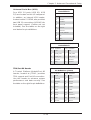
PCI Expansion Slots
The X10DRW-i(T) has one (1) SMC-proprietary PCI-E 3.0 x16 slot, one (1) SMC-
proprietary PCI-E 3.0 x16+x16 slot, and one (1) PCI-E 3.0 x16 Add-On-Module
(AOM) slot for a mezzanine HBA card. PCI slots are controlled by CPUs: both CPUs
must be installed to utilize all slots. See Chapter 5 for details.
Rear I/O Ports
Ports on the I/O backplane include one COM port, a VGA port, four USB 2.0 ports,
two gigabit (1028R-WTR) or 10-gigabit (1028R-WTRT) Ethernet ports and one IPMI
port. A UID (Unit Identifi er) button and LED are also located beside the VGA port.
1-3 Server Chassis Features
The SC116TS-R706WBP is Supermicro's third-generation 1U chassis and features
ten (10) SATA-3 2.5" hard drive bays and two high-effi ciency power supplies. The
following is a general outline of the main features of the SC116 chassis.
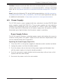
System Power
The SC116TS-R706WBP features a 700/750 Watt power supply composed of two
separate power modules to provide power redundancy (part# PWS-706P-1R). This
power redundancy feature allows you to replace a failed power supply module
without shutting down the system.
Note: The power supplies are both redundant, hot-plug.
Hard Drive Subsystem
The SC116 chassis was designed to support ten hot-swap SATA hard drives.
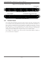
Front Control Panel
The control panel on the SC116 provides important system monitoring and control
information. LEDs indicate power on, network activity, hard disk drive activity and
a UID (Universal Information) LED. Also present are a main power button and a
UID button.

1-4
SUPERSERVER 1028R-WTR(T) USER'S MANUAL
Cooling System
The SC116 chassis has an innovative cooling design that features up to six sets
of 4-cm counter-rotating fans located in the middle section of the chassis. These
fans are 1U high and are powered by 4-pin connectors, with chassis fan speed
controlled by IPMI software. The power supply module also includes a cooling fan.
Note: The fans in this system are NOT redundant, hot-plug.
1-6 Advanced Power Management
Intel® Intelligent Power Node Manager (IPNM)
The Intel
®
Intelligent Power Node Manager (IPNM) provides your system with
real-time thermal control and power management for maximum energy effi ciency.
Although IPNM Specifi cation Version 2.0 is supported by the BMC (Baseboard
Management Controller), your system must also have IPNM-compatible
Manageability Engine (ME) 2.0 fi rmware installed to use this feature.
Manageability Engine (ME)
The Manageability Engine, which is an ARC controller embedded in the IOH (I/O
Hub), provides Server Platform Services (SPS) to your system. The services
provided by SPS are different from those proveded by the ME on client platforms.

1-5
Chapter 1: Introduction
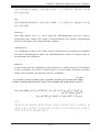
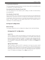
Figure 1-1. Intel PCH-C612 Chipset:
System Block Diagram
Note: This is a general block diagram. Please see Chapter 5 for details.
x16
P1
P1
P0
P0
CPU
FRONT
CPU
DMI
PE1
PE2
PE3
PE3
PE1PE2
DDR4 DIMM
4,5
port 0,1
REAR
DDR4 DIMM
#1
#2
DDR4 DIMM
A
G
x16
RIGHT
SLOT
SXB2
PCIE 3.0
x16
x16
RJ45
JLAN1
UL1
RJ45
JLAN2
PHY
RTL8211E
PET
[3,4,6,7]
DMI
PET5
LPC
USB2.0
[6]
QPI
Dual
LAN
I350BT2
PROCESSOR
PROCESSOR
QPI
DDR4 DIMM
#2
#1
DDR4 DIMM
DDR4 DIMM
BMC
SATA
Gen3
[0..5]
2,3
REAR
AST2400
DDR4 DIMM
B
DDR4 DIMM
C
D
SocketID 01
E
H
F
#1
#2
#1
#2
#1
2#
2
#
#1
#1
#2
#1
#2
x16
Left
SLOT
SXB1B
(lower)
PCIE
3.0
x16
SocketID 00
Left
SLOT
SXB1B
(Upper)
PCIE
3.0x16
AOM
J35
PCIE
3.0
x16
PCH
SPI
SPI
FLASH
32MB
BMC
DDR3
VGA
IPMI
LAN
RJ45
TPM
Header
sSATA
Gen3
[0..3]
HDR
2x5
WIO Slots
SXB1A
SXB1B
SXB1C
SXB2
PCIE x16
Upper Lower
PCIE x16 PCIE x16
Left Slot
Right Slot
HWM
COM1
USB2.0
[0..5]
USB3.0
[1..6]
NC _SI(RMII)
x8
S-SATA3
SPI
FLASH
16MB
BIOS
DMI
S-SATA2
S-SATA1
S-SATA0
I-SATA0
I-SATA1
I-SATA2
I-SATA3
I-SATA4
I-SATA5
Rear

1-6
SUPERSERVER 1028R-WTR(T) USER'S MANUAL
1-4 Contacting Supermicro
Headquarters
Address: Super Micro Computer, Inc.
980 Rock Ave.
San Jose, CA 95131 U.S.A.
Tel: +1 (408) 503-8000
Fax: +1 (408) 503-8008
Email: [email protected] (General Information)
[email protected] (Technical Support)
Web Site:
www.supermicro.com
Europe
Address: Super Micro Computer B.V.
Het Sterrenbeeld 28, 5215 ML
's-Hertogenbosch, The Netherlands
Tel: +31 (0) 73-6400390
Fax: +31 (0) 73-6416525
Email: [email protected] (General Information)
[email protected] (Technical Support)
[email protected] (Customer Support)
Web Site:
www.supermicro.nl
Asia-Pacifi c
Address: Super Micro Computer, Inc.
3F, No. 150, Jian 1st Rd.
Zhonghe Dist., New Taipei City 235
Taiwan (R.O.C)
Tel: +886-(2) 8226-3990
Fax: +886-(2) 8226-3992
Email: [email protected]
Web Site:
www.supermicro.com.tw

Chapter 2: Server Installation
2-1
Chapter 2
Server Installation
2-1 Overview
This chapter provides a quick setup checklist to get your SuperServer 1028R-WTR(T)
up and running. Following these steps in the order given should enable you to have
the system operational within a minimum amount of time. This quick setup assumes
that your system has come to you with the processors and memory preinstalled. If
your system is not already fully integrated with a serverboard, processors, system
memory etc., please turn to the chapter or section noted in each step for details on
installing specifi c components.
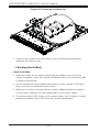
2-2 Unpacking the System
You should inspect the box the SuperServer 1028R-WTR(T) was shipped in and
note if it was damaged in any way. If the server itself shows damage you should
fi le a damage claim with the carrier who delivered it.
Decide on a suitable location for the rack unit that will hold the SuperServer
1028R-WTR(T). It should be situated in a clean, dust-free area that is well ventilated.
Avoid areas where heat, electrical noise and electromagnetic fi elds are generated.
You will also need it placed near a grounded power outlet. Read the Rack and
Server Precautions in the next section.
2-3 Preparing for Setup
The box the SuperServer 1028R-WTR(T) was shipped in should include two sets of
rail assemblies, two rail mounting brackets and the mounting screws you will need
to install the system into the rack. Follow the steps in the order given to complete
the installation process in a minimum amount of time. Please read this section in
its entirety before you begin the installation procedure outlined in the sections that
follow.
Choosing a Setup Location
• Leave enough clearance in front of the rack to enable you to open the front door
completely (~25 inches) and approximately 30 inches of clearance in the back
of the rack to allow for suffi cient airfl ow and ease in servicing.

2-2
SUPERSERVER 1028R-WTR(T) USER'S MANUAL
• This product is for installation only in a Restricted Access Location (dedicated
equipment rooms, service closets and the like).
• This product is not suitable for use with visual display work place devices
acccording to §2 of the the German Ordinance for Work with Visual Display Units.
2-4 Warnings and Cautions
Rack Precautions
• Ensure that the leveling jacks on the bottom of the rack are fully extended to
the fl oor with the full weight of the rack resting on them.
• In single rack installation, stabilizers should be attached to the rack. In multiple
rack installations, the racks should be coupled together.
• Always make sure the rack is stable before extending a component from the
rack.
• You should extend only one component at a time - extending two or more
simultaneously may cause the rack to become unstable.
Server Precautions
• Review the electrical and general safety precautions in Chapter 4.
• Determine the placement of each component in the rack before you install the
rails.
• Install the heaviest server components on the bottom of the rack fi rst, and then
work up.
• Use a regulating uninterruptible power supply (UPS) to protect the server from
power surges, voltage spikes and to keep your system operating in case of a
power failure.
• Allow any hot plug drives and power supply modules to cool before touching
them.
• Always keep the rack's front door and all panels and components on the servers
closed when not servicing to maintain proper cooling.

Chapter 2: Server Installation
2-3
Rack Mounting Considerations
Warning! To prevent bodily injury when mounting or servicing this unit in a
rack, you must take special precautions to ensure that the system remains stable.
The following guidelines are provided to ensure your safety:
• This unit should be mounted at the bottom of the rack if it is the only unit in
the rack.
• When mounting this unit in a partially fi lled rack, load the rack from the bottom
to the top with the heaviest component at the bottom of the rack.
• If the rack is provided with stabilizing devices, install the stabilizers before
mounting or servicing the unit in the rack.
Ambient Operating Temperature
If installed in a closed or multi-unit rack assembly, the ambient operating
temperature of the rack environment may be greater than the ambient temperature
of the room. Therefore, consideration should be given to installing the equipment
in an environment compatible with the manufacturer’s maximum rated ambient
temperature (Tmra).
Reduced Airfl ow
Equipment should be mounted into a rack so that the amount of airfl ow required
for safe operation is not compromised.
Mechanical Loading
Equipment should be mounted into a rack so that a hazardous condition does not
arise due to uneven mechanical loading.
Circuit Overloading
Consideration should be given to the connection of the equipment to the power
supply circuitry and the effect that any possible overloading of circuits might have
on overcurrent protection and power supply wiring. Appropriate consideration of
equipment nameplate ratings should be used when addressing this concern.
Reliable Ground
A reliable ground must be maintained at all times. To ensure this, the rack
itself should be grounded. Particular attention should be given to power supply
connections other than the direct connections to the branch circuit (i.e. the use of
power strips, etc.).

2-4
SUPERSERVER 1028R-WTR(T) USER'S MANUAL
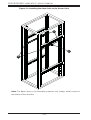
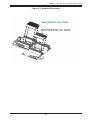
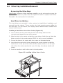
2-5 Rack Mounting Instructions
This section provides information on installing the SC116 chassis into a rack unit with
the rails provided. There are a variety of rack units on the market, which may mean
the assembly procedure will differ slightly. You should also refer to the installation
instructions that came with the rack unit you are using.
NOTE: This rail will fi t a rack between 26" and 33.5" deep.
Warning: Do not pick up the server with the front handles. They are
designed to pull the system from a rack only.
Stability Hazard: The rack stabilizing mechanism must be in place, or the
rack must be bolted to the fl oor before you slide the unit out for servicing. Failure
to stabilize the rack can cause the rack to tip over.
Warning: Slide rail mounted equipment is not to be used as a shelf or a
work space.
Page is loading ...
Page is loading ...
Page is loading ...
Page is loading ...
Page is loading ...
Page is loading ...
Page is loading ...
Page is loading ...
Page is loading ...
Page is loading ...
Page is loading ...
Page is loading ...
Page is loading ...
Page is loading ...
Page is loading ...
Page is loading ...
Page is loading ...
Page is loading ...
Page is loading ...
Page is loading ...
Page is loading ...
Page is loading ...
Page is loading ...
Page is loading ...
Page is loading ...
Page is loading ...
Page is loading ...
Page is loading ...
Page is loading ...
Page is loading ...
Page is loading ...
Page is loading ...
Page is loading ...
Page is loading ...
Page is loading ...
Page is loading ...
Page is loading ...
Page is loading ...
Page is loading ...
Page is loading ...
Page is loading ...
Page is loading ...
Page is loading ...
Page is loading ...
Page is loading ...
Page is loading ...
Page is loading ...
Page is loading ...
Page is loading ...
Page is loading ...
Page is loading ...
Page is loading ...
Page is loading ...
Page is loading ...
Page is loading ...
Page is loading ...
Page is loading ...
Page is loading ...
Page is loading ...
Page is loading ...
Page is loading ...
Page is loading ...
Page is loading ...
Page is loading ...
Page is loading ...
Page is loading ...
Page is loading ...
Page is loading ...
Page is loading ...
Page is loading ...
Page is loading ...
Page is loading ...
Page is loading ...
Page is loading ...
Page is loading ...
Page is loading ...
Page is loading ...
Page is loading ...
Page is loading ...
Page is loading ...
Page is loading ...
Page is loading ...
Page is loading ...
Page is loading ...
Page is loading ...
Page is loading ...
Page is loading ...
Page is loading ...
Page is loading ...
Page is loading ...
Page is loading ...
Page is loading ...
Page is loading ...
Page is loading ...
Page is loading ...
Page is loading ...
Page is loading ...
Page is loading ...
Page is loading ...
Page is loading ...
Page is loading ...
Page is loading ...
Page is loading ...
Page is loading ...
Page is loading ...
Page is loading ...
-
 1
1
-
 2
2
-
 3
3
-
 4
4
-
 5
5
-
 6
6
-
 7
7
-
 8
8
-
 9
9
-
 10
10
-
 11
11
-
 12
12
-
 13
13
-
 14
14
-
 15
15
-
 16
16
-
 17
17
-
 18
18
-
 19
19
-
 20
20
-
 21
21
-
 22
22
-
 23
23
-
 24
24
-
 25
25
-
 26
26
-
 27
27
-
 28
28
-
 29
29
-
 30
30
-
 31
31
-
 32
32
-
 33
33
-
 34
34
-
 35
35
-
 36
36
-
 37
37
-
 38
38
-
 39
39
-
 40
40
-
 41
41
-
 42
42
-
 43
43
-
 44
44
-
 45
45
-
 46
46
-
 47
47
-
 48
48
-
 49
49
-
 50
50
-
 51
51
-
 52
52
-
 53
53
-
 54
54
-
 55
55
-
 56
56
-
 57
57
-
 58
58
-
 59
59
-
 60
60
-
 61
61
-
 62
62
-
 63
63
-
 64
64
-
 65
65
-
 66
66
-
 67
67
-
 68
68
-
 69
69
-
 70
70
-
 71
71
-
 72
72
-
 73
73
-
 74
74
-
 75
75
-
 76
76
-
 77
77
-
 78
78
-
 79
79
-
 80
80
-
 81
81
-
 82
82
-
 83
83
-
 84
84
-
 85
85
-
 86
86
-
 87
87
-
 88
88
-
 89
89
-
 90
90
-
 91
91
-
 92
92
-
 93
93
-
 94
94
-
 95
95
-
 96
96
-
 97
97
-
 98
98
-
 99
99
-
 100
100
-
 101
101
-
 102
102
-
 103
103
-
 104
104
-
 105
105
-
 106
106
-
 107
107
-
 108
108
-
 109
109
-
 110
110
-
 111
111
-
 112
112
-
 113
113
-
 114
114
-
 115
115
-
 116
116
-
 117
117
-
 118
118
-
 119
119
-
 120
120
-
 121
121
-
 122
122
-
 123
123
-
 124
124
-
 125
125
-
 126
126


Supermicro SUPERO SUPERSERVER 1028R-WTR Series User manual
- Category
- Server barebones
- Type
- User manual
- This manual is also suitable for
Ask a question and I''ll find the answer in the document
Finding information in a document is now easier with AI
Related papers
-
Supermicro SUPERO SUPERSERVER 1028R-WTR Series User manual
-
Supermicro SUPERO SUPERSERVER 1028R-WTR Series User manual
-
Supermicro SUPERO X10DRW-i User manual
-
-
Supermicro A+ Series User manual
-
-
-
-
-
Other documents
-
 Supero SUPERSERVER 2027TR-D70RF+ User manual
-
 Sugon I620-G20 User manual
-
Leadtek WinFast WS2030 User manual
-
 STONEFLY VSO User manual
-
NEC SX-Aurora TSUBASA A300-2 User manual
-
-
-
ATX UCrypt IP to Analog 2 Installation & Operation Manual
-
 Silicon Graphics Rackable C1110-RP6 User manual
-
 Silicon Graphics Rackable C1104-GP2 System User's Manual


