2
g
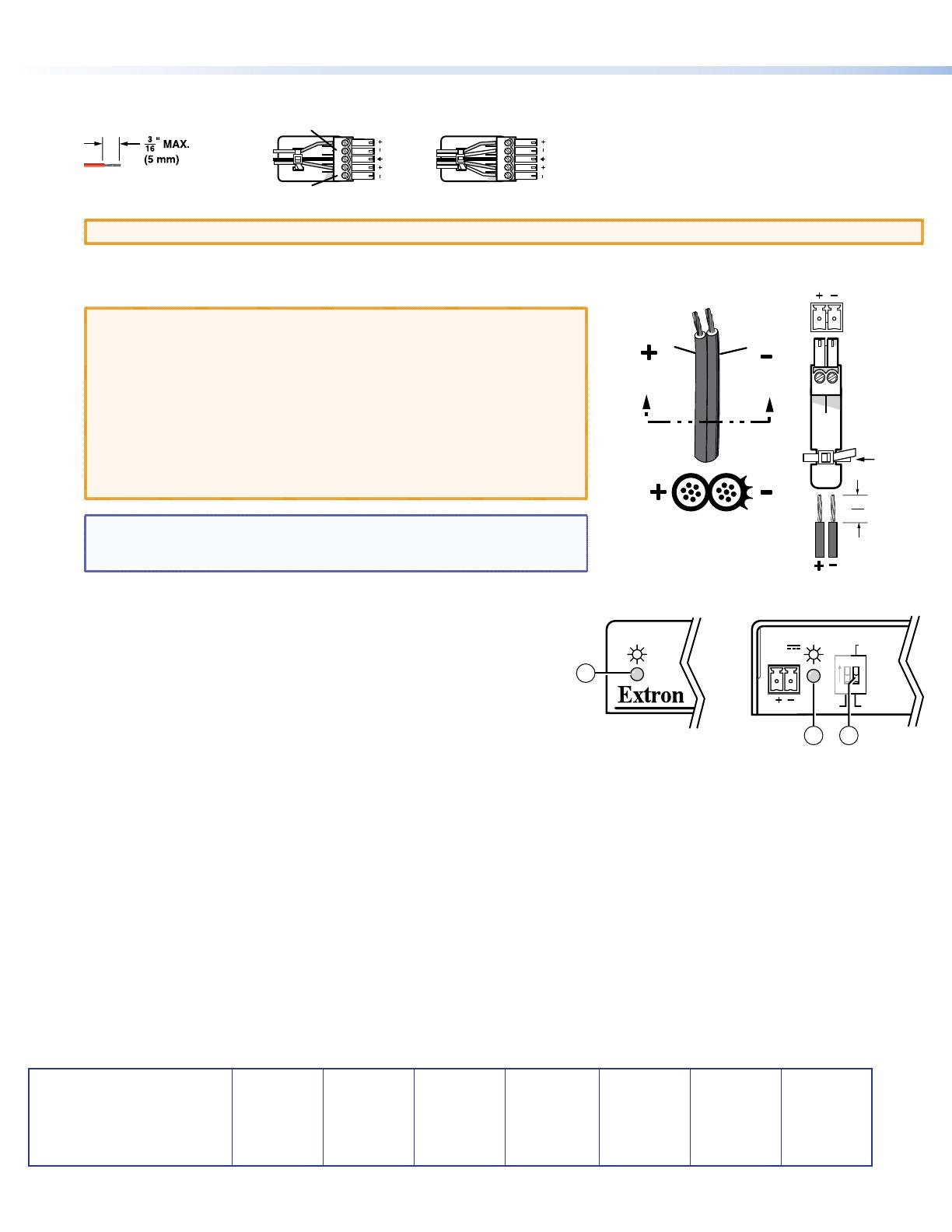
Audio Output connector (Rx) — Connect a balanced or unbalanced stereo or mono audio device to the receiver via the Audio
captive screw connector. See the drawing below.
Unbalanced Stereo Output Balanced Stereo Output
Do not tin the wires!
Tip
Ring
Tip
Ring
Sleeves
Tip
No Ground Here
Tip
Sleeves
LR
LR
ATTENTION: Connect the sleeves to the ground contact. DO NOT connect the sleeves to the negative (–) contacts.
h
Power connector — Connect an IEC power cord between the included 12 VDC power supply and a 100-240 VAC, 50-60 Hz source.
Connect the power supply to either unit as shown at right.
ATTENTION: This product is intended to be supplied by a Listed Power
Unit marked “Class 2” or “LPS,” rated 12 VDC, 1.0 A. Always use a
power supply supplied by or specied by Extron. Use of an unauthorized
power supply voids all regulatory compliance certication and may cause
damage to the supply and the end product. Unless otherwise stated,
the AC/DC adapters are not suitable for use in air handling spaces or
in wall cavities. The installation must always be in accordance with
the applicable provisions of National Electrical Code ANSI/NFPA 70,
article 75 and the Canadian Electrical Code part 1, section 16. The power
supply shall not be permanently xed to a building structure or similar
structure.
NOTE: Only one power supply is required. A single power supply connected
to either unit in the pair powers both units. A power supply is included
with each transmitter.
Operation
Rear
(Tx)
LOCAL
SPARE
REMOTE
DDC ROUTE
POWER
12V
0.8 A MAX
1 2
ON
2 3
1
After all devices are powered up, the system is fully operational. See the
denitions of the power indications (shown at right), below:
a Power LED (front panel) —
Amber — The unit is receiving power, either locally or remotely (on the DTP
cable).
Green — The unit is powered on and is receiving an active DVI signal, either
on the DVI input if a transmitter, or transmitted on the DTP cable if a receiver.
b Power LED (rear panel) —
Amber — The unit is receiving power remotely (on the DTP cable).
Green — The unit is receiving power locally.
c DDC Route switch — This rear panel switch selects either the remote or local DVI display as the display data channel (DDC)
reference for EDID and HDCP communication.
If any problems are encountered, verify that the cables are routed and connected properly. If your problems persist, call the Extron S3
Sales and Technical Support Hotline that is closest to you, at the number shown below.
68-2342-50
Rev A
12 12
Power Supply
Output Cord
SECTION A–A
Ridges
Smooth
Captive
Screw
Connector
Tie Wrap
3"
16 (5 mm) Max.
Extron Headquarters
+800.633.9876 Inside USA/Canada Only
Extron USA - West Extron USA - East
+1.714.491.1500 +1.919.850.1000
+1.714.491.1517 FAX +1.919.850.1001 FAX
Extron Europe
+800.3987.6673
Inside Europe Only
+31.33.453.4040
+31.33.453.4050 FAX
Extron Asia
+800.7339.8766
Inside Asia Only
+65.6383.4400
+65.6383.4664 FAX
Extron Japan
+81.3.3511.7655
+81.3.3511.7656 FAX
Extron China
+4000.EXTRON
+4000.398766
Inside China Only
+86.21.3760.1568
+86.21.3760.1566 FAX
Extron Middle East
+971.4.299.1800
+971.4.299.1880 FAX
Extron Korea
+82.2.3444.1571
+82.2.3444.1575 FAX
Extron India
1800.3070.3777
Inside India Only
+91.80.3055.3777
+91.80.3055.3737
FAX
© 2012 Extron Electronics All rights reserved. All trademarks mentioned are the property of their respective owners. www.extron.com
DTP DVI 330 • Setup Guide (Continued)


