Page is loading ...

For Your Records and Warranty
Assistance
Model Name: _____________________
Catalog/Model No.: ________________
Serial No.: ________________________
Date Purchased: ___________________
Where Purchased: _________________
For reference also attach your receipt or a
copy of your receipt to the manual.
TYPE 3 Models
installation and
operation manual
for Hunter
Ceiling Fans
42700-01•01/15/08

2
42700-01•01/15/08•HunterFanCompany
Table of Contents
1•GettingReady ...................................................4
2•InstallingtheCeilingPlate ..........................5
3•AssemblingtheBlades .................................6
4•AssemblingtheTopHousing ...................7
5•AssemblingandHangingtheFan ..........8
6•SettingtheRemoteTransmitter
andReveiver .......................................................9
7•WiringtheFan ...............................................10
8•InstallingtheCanopy ................................. 12
9•CompletingYourInstallationWith
a Light Fixture ................................................. 13
10•OperatingtheRemoteControland
MountingtheHolder ............................... 14
11•OperatingandCleaning
Your Ceiling Fan ......................................... 15
12•Troubleshooting ......................................... 16
© 2007 Hunter Fan Company
YournewHunter
®
ceiling fan is an addition to your home or office that
willprovidecomfortandperformanceformanyyears.isinstallation
andoperationmanualgivesyoucompleteinstructionsforinstalling
and operating your fan.
We are proud of our work. We appreciate the opportunity to supply
youwiththebestceilingfanavailableanywhereintheworld.
Beforeinstallingyourfan,foryourrecordsandwarrantyassistance,
recordinformationfromthecartonandHunternameplatelabel
(located on the top of the fan motor housing).
Cautions and Warnings
• READ THIS ENTIRE MANUAL CAREFULLY BEFORE BEGINNING
INSTALLATION. SAVE THESE INSTRUCTIONS.
•UseonlyHunterreplacementparts.
•Toreducetheriskofpersonalinjury,attachthefandirectlytothe
supportstructureofthebuildingaccordingtotheseinstructions,
and use only the hardware supplied.
•Toavoidpossibleelectricalshock,beforeinstallingyourfan,
disconnectthepowerbyturningothecircuitbreakerstothe
outletboxandassociatedwallswitchlocation.Ifyoucannotlock
thecircuitbreakersintheoposition,securelyfastenaprominent
warningdevice,suchasatag,totheservicepanel.
•Allwiringmustbeinaccordancewithnationalandlocalelectrical
codesandANSI/NFPA70.Ifyouareunfamiliarwithwiring,usea
qualified electrician.
•Toreducetheriskofpersonalinjury,donotbendtheblade
attachmentsystemwheninstalling,balancing,orcleaningthefan.
Neverinsertforeignobjectsbetweenrotatingfanblades.
•Toreducetheriskofre,electricalshock,ormotordamage,donot
useasolid-statespeedcontrolwiththisfan.UseonlyHunterspeed
controls.
Welcome

3
42700-01•01/15/08•HunterFanCompany
Installer’s Choice and Optional Accessories
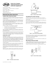
Understanding Mounting and Installer’s Choice®
Hunter’spatented3-positionmountingsystemprovidesyoumaximum
installationexibilityandease.YoucaninstallyourHunterfaninone
ofthreeways,dependingonceilingheightandyourpreference:Low
Prole,Standard,orAngledmounting.estepsinthismanualinclude
instructionsforallthreeInstaller’sChoicemountingmethods.
Considering Optional Accessories
ConsiderusingHunter’soptionalaccessories,includingawall-mounted
orremotespeedcontrol.Toinstallandusetheaccessories,follow
the instructions included with each product. For quiet and optimum
performanceofyourHunterfan,useonlyHunterspeedcontrols.
Forceilingshigherthan8feet,youcanpurchase
Hunterextensiondownrods.AllHunterfansuse
sturdy3/4in.diameterpipetoassurestabilityand
wobble-freeperformance.
Standard Mounting hangs from the
ceilingbyadownrod(included).
Angled Mounting recommended for a
vaultedorangledceiling
SupportBrace
Standard
Mounting
Style
Ceiling
OutletBox
SupportBrace
Ceiling
OutletBox
Angled
Mounting
Style
Low Profile Mounting fits close to the
ceiling,recommendedforceilingsless
than8feethigh
SupportBrace
Low Profile
Mounting
Style
Ceiling
OutletBox
8
12
CAUTION: To
reduce the risk of
personalinjury,attach
the fan directly to the
support structure of
thebuildingaccording
totheseinstructions,
and use only the
hardware supplied.

4
42700-01•01/15/08•HunterFanCompany
1 • Getting Ready
Toinstallaceilingfan,besureyoucandothefollowing:
•Locatetheceilingjoistorothersuitablesupportinceiling.
•Drillholesforandinstallwoodscrews.
•Identifyandconnectelectricalwires.
•Lift40pounds.
Ifyouneedhelpinstallingthefan,yourHunterfandealercandirect
you to a licensed installer or electrician.
Gathering the Tools
You will need the following tools for installing the fan:
•Electricdrillwith9/64in.bit
•Standardscrewdriver(magnetictiprecommended)
•Phillips-headscrewdriver(magnetictiprecommended)
•Wrenchorpliers
•Ladder(heightdependentuponinstallationsite)
Checking Your Fan Parts
Carefullyunpackyourfantoavoiddamagetothefanparts.Referto
theincludedPartsGuide.Checkforanyshippingdamagetothemotor
orfanblades.Ifanypartsaremissingordamaged,contactyourHunter
dealerorcallHunterTechnicalSupportDepartmentat888-830-1326.
Preparing the Fan Site
Beforeyoubegininstallingthefan,followalltheinstructionsin
the pullout sheet called “Preparing the Fan Site.” Proper ceiling fan
locationandattachmenttothebuildingstructureareessentialfor
safety,reliableoperation,maximumeciency,andenergysavings.
Installing Multiple Fans?
Ifyouareinstallingmorethan
onefan,keepthefanbladesand
bladeirons(ifapplicable)insets,
as they were shipped.

5
42700-01•01/15/08•HunterFanCompany
2 • Installing the Ceiling Plate
CAUTION: Toavoidpossibleelectricalshock,beforeinstallingyourfan,
disconnectthepowerbyturningothecircuitbreakerstotheoutletbox
andassociatedwallswitchlocation.Ifyoucannotlockthecircuitbreakers
intheoposition,securelyfastenaprominentwarningdevice,suchasa
tag,totheservicepanel.
2-1. Drill two pilot holes into the wood support structure through the
outermostholesintheoutletbox.epilotholesshouldhavea
diameter of 9/64 in.
2-2.Yourfancomeswiththreeneoprenenoiseisolators(“Isolators”).
Positiontheisolatorsbetweentheceilingplateandceilingby
inserting the raised areas on each isolator into the holes in the
ceiling plate.
2-3. readtheleadwiresfromtheoutletboxdownthroughthehole
in the middle of the ceiling plate.
2-4. Aligntheslottedholesintheceilingplatewiththepilotholesyou
drilled in the wood support structure. For proper alignment use
slotted holes directly across from each other.
Note:eisolatorsshouldbeushagainsttheceiling.
2-5. Placeaatwasheroneachofthetwo3in.woodscrewsandpass
the screws through the slotted holes in the ceiling plate into the
pilot holes you drilled.
Tighten the screws into the 9/64 in. pilot holes; do not use
lubricantsonthescrews.Donotovertighten.
Step 2-2
Flat Washer
3 in. Wood Screw
Steps 2-3 – 2-5
For Angled Ceilings:Besuretoorient
the ceiling plate so that the hook and
one of the threaded screw holes in the
ceiling plate are on the lower side.
Ceiling
Plate
Isolator

6
42700-01•01/15/08•HunterFanCompany
3 • Assembling tbe Blades
Step 3-1
Step 3-2
Holes
Fan Motor
3-1.Insertbladeintoslot.Aligntheholesonthebladewiththeholes
in the fan motor.
3-2.Slideatwashersontotheshaftsofthebladeassemblyscrews.
3-3. Attachthebladetothemotorusingthebladeassemblyscrews.
3-4.Repeatforeachblade.
BladeAssembly
Screw
Flat Washer
3 • Assembling the Blades
3 • Assembling tbe Blades

7
42700-01•01/15/08•HunterFanCompany
4 • Assembling the Top Housing
4-1. Toassemblethehousingtothehangeradapter,alignthethree
raisedtabsonthehangeradapterwiththethreenarrownotches
in the top housing. Make certain the housing sits flat on the
adapter.
4-2. Installthree(3)assemblyscrewsandtightenthemsecurely.
Steps 4-1 – 4-2
TopHousing
AssemblyScrew
HangerAdapter

8
42700-01•01/15/08•HunterFanCompany
5 • Assembling and Hanging the Fan
Steps 5-4 – 5-5
Low Profile Screw
Low Profile Washer
Steps 5-1 – 5-2
Downrod
Canopy
Youcanassembleyourfanforstandardmounting(steps5-1–5-2)
orforlowprolemounting(steps5-3–5-5).Note: For low profile
mounting,thedownrodisreplacedwiththelowprolewasher.
5-1.Toassemblefantohangdownfromaatorangledceiling,insert
the downrod through the canopy. Feed the wires from the fan
through the downrod.
5-2.Loosenthesquareheadsetscrewontheadaptertoinstallthe
pipeandballassembly.Note:Whenthepipeandballassembly
isfullyinstalled,2-3threadsonthepipewillstillbevisible;thisis
normal. Securely retighten the set screw with a wrench or pliers.
SkiptoStep5-6.
CAUTION:eadapterhasaspecialcoatingonthethreads.Do
notremovethiscoating;thecoatingpreventsthedownrodfrom
unscrewing.Onceassembled,donotremovethedownrod.
5-3. Removethesetscrewfromtheadapter.
5-4.Placethelowprolewasher(lipdown)intothecanopy.Besure
the green ground wire is pointing up toward the ceiling.
5-5.Aligntheholesinthewasherwiththeholesintheadapter.
Assemblesecurelywiththreelowprolescrews.
Note:Beforehangingthefan,alignandengagethetwotabsfromthe
bottomofthecanopyandthetwogroovesinthehangerball.
5-6.Raisethefanandplacethehookontheceilingplatethroughthe
round hole in the rim.
WARNING:Fanmayfallifnotassembledasdirectedinthese
installation instructions.
Step 5-6
Round
Hole

9
42700-01•01/15/08•HunterFanCompany
6 • Setting the Remote Transmitter and Receiver
CAUTION:eremotecontroldevicecomplieswithpart15oftheFCCrules.
ChangesormodicationsnotexpresslyapprovedbyHunterFanCompanycouldvoid
your authority to operate this equipment.
Operationissubjecttothefollowingtwoconditions:
1.isdevicemaynotcauseharmfulinterference.
2.isdevicemustacceptanyinterferencereceived,includinginterferencethatmay
cause undesired operation.
WARNING:UseonlytheHunterFanspeedcontrolsuppliedwiththisfan.
IMPORTANT!Beforeyouchangethejumpersettings,makesurethe
batteryisnotconnectedtothetransmitter.
6-1. Changethepositionofthejumpersintheremotetransmitter
andthereceiver.Makesurethatthejumpersmatchintheremote
receiverandtransmitter.Iftheydon’tmatch,thetransmitterwill
not function.
6-2. Installtheincluded12-voltbatteryintothetransmitter.
Setting Transmitter and Receiver Codes
Whentwoormorefansarelocatedneareachother,youmaydesire
tohavethereceiver/transmitterforeachfansettoadierentcode,
sothattheoperationofonefandoesnotaecttheoperationofthe
other fans.
ejumpersforthereceiverarelocatedontheatsurfaceof
thereceiver.ejumpersforthetransmitterareinthebattery
compartment.ejumpersareverysmall;youcanmovethemmost
easily using a small pair of pliers or tweezers.
4321
4321
4321
4321
4 = off
3 = on
2 = on
1 = on
4 = off
3 = on
2 = off
1 = on
ReceiverJumpers
4321
4321
4321
4321
4 = off
3 = on
2 = on
1 = on
4 = off
3 = on
2 = off
1 = on
Example Jumpers Settings
Receiver1 Receiver2
Transmitter 2Transmitter 1
4321
4321
4321
4321
4 = off
3 = on
2 = on
1 = on
4 = off
3 = on
2 = off
1 = on

10
42700-01•01/15/08•HunterFanCompany
7 • Wiring the Fan
All wiring must be in accordance with national and local electrical
codes and ANSI/NFPA 70. If you are unfamiliar with wiring, use a
qualified electrician.
Wallswitchesarenotincluded.Selectanacceptablegeneral-useswitch
in accordance with national and local electrical codes.
7-1. Disconnectthepowerbyturningothecircuitbreakerstothe
outletboxandassociatedwallswitchlocation.
7-2. Placethereceiverinsidethecanopy,makingsurethatthe
dipswitchesandtheovalshapedholesinthebottomofthe
receiverarefacingdowntowardthebottomofthecanopy.
7-3. Spreadthereceiverleadwirestoeachsideandfeedthewiresfrom
thetopofthefanthroughtheopenslotinthereceiver.
7-4. Placethereceiverinthecanopy.Makesuretheslotinthereceiver
is aligned with the hook in the ceiling plate.
7-5. Toconnectthewires,holdthebaremetalleadstogetherand
placeawireconnectoroverthem,thentwistclockwiseuntiltight.
Usingthesmallwireconnectors,connectthefantothereceiveras
follows:
•Connecttheyellowwirefromthefantotheyellowwirefrom
thereceiver.
•Connectthepinkwirefromthefantothepinkwirefromthe
receiver.
•Connectthegreywirefromthefantothegreywirefromthe
receiver.
•Connecttheredwirefromthefantotheredwirefromthe
receiver.
•Connecttheblackwirewithawhitestripefromthefantothe
blackwirewithawhitestripefromthereceiver.
•Connectthewhitewirefromthefantothewhitewire
(LIGHTOUT)fromthereceiver.
Steps 7-5 – 7-6
Large Wire
connector
Small Wire
connector

11
42700-01•01/15/08•HunterFanCompany
7-6. Usingthelargewireconnectors,connectthefanandreceiverto
the power wires as follows:
•Connectthewhitewire(A/CIN)fromthereceivertothewhite
wire from the ceiling.
•Connecttheblackwirefromthereceivertotheblackwirefrom
the ceiling.
CAUTION:Besurenobarewireorwirestrandsarevisibleafter
making connections.
7-7. Runthethinwhiteantennawirefromthereceiverthroughone
oftheslotsintheceilingplate.(Forbestreception,makesurethe
end of the antenna is exposed at the top of the canopy.)
7-8. Connectthegreengroundwiresfromtheceilingplateandthe
downrod to the ground wire from the ceiling.
7-9.
Pushallwiresandwireconnectorsbackthroughtheceilingplate
holeintotheoutletbox.Placethegreenandwhitewiresona
separatesideoftheoutletboxfromtheotherwires.

12
42700-01•01/15/08•HunterFanCompany
8 • Installing the Canopy
8-1. Holdingthecanopy,raisethefanothehook.
8-2.Aligntheholesinthecanopywiththemountingholesonthe
ceiling plate.
8-3.Insertandtightenthemountingscrewssecurely.
Steps 8-1– 8-3
Mounting Screw
Canopy

13
42700-01•01/15/08•HunterFanCompany
9 • Completing Your Installation
9-1. Partially install two light kit fitter screws into the light kit
mounting plate.
9-2.readtheplugconnectorfromthefanthroughthelightkittter.
9-3.Alignthekeyholesinthelightkittterwiththetwopartially
installed screws and rotate to engage the screws in the narrow
ends of the keyholes.
9-4.Installtheremainingscrewtosecurethelightkitttertothelight
kit mounting plate. Securely tighten all three screws.
9-5.Connectthe2-pinplugconnectorfromthefantothe2-pinplug
connectorfromtheballast.
9-6.Attachtheballasttothelightkittterwithtwoballastscrews.
9-7.Installtheincluded22Wattuorescentbulbintothehookson
the fitter.
9-8.Connectthe4pinplugfromtheballasttotheuorescentbulb.
9-9.Placetheglassglobeintotheglobetrimband.Alignthethree
holesinthetrimbandwiththethreeholesinthetter.Installand
securely tighten all three screws.
Steps 9-1 – 9-8
Step 9-9
Light Kit
Fitter
Ballast
Fluorescent
Bulb
Glass
Globe
Globe
Trim
Band

14
42700-01•01/15/08•HunterFanCompany
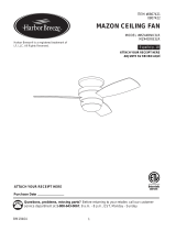
10 • Operating the Remote Control and Mounting the Holder
10-1.eremotetransmitterhasindividualbuttonsforturningthefan
oandonandcontrollingthelightandfanspeed.
10-2.Forbestoperation,startthefanbypressinghigh,thenselectyour
desired speed.
10-3.ereversingswitchreversesthedirectionofthefan.
10-4.PresstheOFFbuttontoturnthefano.
10-5.elightbuttonturnsthelightontofullbrightness.Pushthe
lightbuttonagaintoturnothelight.
10-6. You can mount the remote holder to any toggle switch plate with
thescrewsalreadyintheswitchplate.Or,youcansimplymount
the remote holder on the wall.
10-7.isproductincludesone12-volttype23A,MN-21batteryfor
use with the remote control transmitter. Please contact your local
batteryrecyclingcenterforproperbatterydisposalinformation.
Step 10-6
Fan Light
Fan Speed
High
Fan Speed
Medium
Fan Speed
Low
FanO
ReversingSwitch
Steps 10-1 – 10-5
Step 10-7

15
42700-01•01/15/08•HunterFanCompany
11 • Operating and Cleaning Your Ceiling Fan
11-1. Restorepoweratthemainelectricalpanelandturnonthewall
switch.elightkitshouldturnON.
Note:Toturnonthelightwithouttheremote,turnothewall
switchfor5seconds,thenbackon.elightkitwillturnonat
maximumbrightness.
11-2. Presstheremotecontrol’sHIGHspeedbutton.efanshould
start and reach its maximum speed.
Note: Foreverydayoperation,leavethewallswitchON.Ifthe
remotecontrolwillnotbeusedfor5daysormore,turnthewall
switchOFF.
11-3. Ceilingfansworkbestbyblowingairdownward
(counterclockwisebladerotation)inwarmweathertocoolthe
roomwithadirectbreeze.Incoldweather,havingthefandraw
airupward(clockwisebladerotation)willdistributethewarmer
air trapped at the ceiling around the room without causing a
draft.
11-4. Forcleaningnishes,useasoftbrushorlint-freeclothtoprevent
scratching.Avacuumcleanerbrushnozzlecanremoveheavier
dust.Removesurfacesmudgesoraccumulateddirtanddust
using a mild detergent and a slightly dampened cloth. You may
useanartisticagent,butneverabrasivecleaningagentsasthey
will damage the finish.
11-5. Cleanwoodnishbladeswithafurniturepolishingcloth.
Occasionally,applyalightcoatoffurniturepolishforadded
protectionandbeauty.Cleanpaintedandhigh-glossbladesin
the same manner as the fan finish.
In warm weather,use
downward air flow pattern
In cold weather,useupward
air flow pattern

16
42700-01•01/15/08•HunterFanCompany
12 • Troubleshooting
Problem: Nothing happens; fan does not move.
1.Turnpoweron,replacefuse,orresetbreaker.
2.Loosencanopy,checkallconnectionsaccordingtothewiringthe
fan section.
3. Check the plug connection in the switch housing.
Problem: Noisy operation.
1.Tightenthebladescrewsuntilsnug.
2.Checktoseeifthebladeiscracked.Ifso,replacealltheblades.
3.Besurethattheglassissecure.
Problem: Excessive wobbling.
1.Ifyourfanwobbleswhenoperating,usetheenclosedbalancingkit
andinstructionstobalancethefan.
2.Tightenallbladeand/orbladeironscrews.
3.Turnpowero,supportfanverycarefully,andcheckthatthe
hangerballisproperlyseated.
Ifyouneedpartsorserviceassistance,pleasecall
888-830-1326orvisitusatourWebsiteat
http://www.hunterfan.com.
HunterFanCompany
2500FriscoAvenue
Memphis,Tennessee38114
/