Page is loading ...

Air handling unit
USER’S MANUAL
AIRVENTS

www.ventilation-system.com
2
AirVENTS
CONTENTS
Safety requirements ..................................................................................................................................................................... 3
Purpose ................................................................................................................................................................................................ 6
Designation key ............................................................................................................................................................................ 6
Design................................................................................................................................................................................................... 7
Installation and set-up................................................................................................................................................................ 10
Connection to power supply ................................................................................................................................................ 13
Start-up preparations ..................................................................................................................................................................15
Automation ....................................................................................................................................................................................... 16
Test run ................................................................................................................................................................................................ 16
Operation and maintenance .................................................................................................................................................. 16
Control measurements of operating parameters ..................................................................................................... 21
Storage and transportation rules......................................................................................................................................... 22
Manufacturer’s warranty ........................................................................................................................................................... 23
Certificate of acceptance ........................................................................................................................................................ 25
Seller information .......................................................................................................................................................................... 25
Installation certificate .................................................................................................................................................................. 25
Warranty card ................................................................................................................................................................................. 25

www.ventilation-system.com
3
This user’s manual is a main operating document intended for technical, maintenance, and operating staff.
The manual contains information about purpose, technical details, operating principle, design, and installation of the AirVENTS unit and
all its modifications.
Technical and maintenance staff must have theoretical and practical training in the field of ventilation systems and should be able to
work in accordance with workplace safety rules as well as construction norms and standards applicable in the territory of the country.
The information in this user’s manual is correct at the time of the document’s preparation.
The Company reserves the right to modify the technical characteristics, design, or configuration of its products at any time in order to
incorporate the latest technological developments.
No part of this publication may be reproduced, stored in a retrieval system, or transmitted, in any form or by any means in any information
search system or translated into any language in any form without the prior written permission of the Company.
SAFETY REQUIREMENTS
• Please read the user’s manual carefully prior to installing and operating the unit.
• All user’s manual requirements as well as the provisions of all the applicable local and national
construction, electrical, and technical norms and standards must be observed when installing
and operating the unit.
• The warnings contained in the user’s manual must be considered most seriously since they
contain vital personal safety information.
• Failure to follow the rules and safety precautions noted in this user’s manual may result in an
injury or unit damage.
• After a careful reading of the manual, keep it for the entire service life of the unit.
• While transferring the unit control, the user’s manual must be turned over to the receiving
operator.

www.ventilation-system.com
4
AirVENTS
UNIT INSTALLATION AND OPERATION SAFETY PRECAUTIONS
• Disconnect the unit from
power mains prior to any
installation operations.
• Unpack the unit with care.
• The unit must be grounded!
• While installing the unit, follow
the safety regulations specific
to the use of electric tools.
• Do not change the power
cable length at your own
discretion.
• Do not bend the power cable.
• Avoid damaging the power
cable.
• Do not put any foreign objects
on the power cable.
• Do not lay the power cable of
the unit in close proximity to
heating equipment.
• Do not use damaged
equipment or cables when
connecting the unit to power
mains.
• Do not operate the unit
outside the temperature range
stated in the user’s manual.
• Do not operate the unit
in aggressive or explosive
environments.
• Do not touch the unit controls
with wet hands.
• Do not carry out the
installation and maintenance
operations with wet hands.
• Do not wash the unit with
water.
• Protect the electric parts of the
unit against ingress of water.
• Do not allow children to
operate the unit.
• Disconnect the unit from
power mains prior to any
technical maintenance.
• Do not store any explosive or
highly flammable substances
in close proximity to the unit.
• When the unit generates
unusual sounds, odour, or
emits smoke, disconnect it
from power supply and contact
the Seller.
• Do not open the unit during
operation.
• Do not direct the air flow
produced by the unit towards
open flame or ignition sources.

www.ventilation-system.com
5
• Do not block the air duct when
the unit is switched on.
• In case of continuous
operation of the unit,
periodically check the security
of mounting.
• Do not sit on the unit and
avoid placing foreign objects
on it.
• Use the unit only for its
intended purpose.
THE PRODUCT MUST BE DISPOSED SEPARATELY AT THE END OF ITS SERVICE LIFE.
DO NOT DISPOSE THE UNIT AS UNSORTED DOMESTIC WASTE.

www.ventilation-system.com
6
AirVENTS
ИThe AirVENTS air handling unit consists of a number of connectable assembly units with various design to enable numerous composition
options for various air handling processes. The unit is designed for air conditioning, ventilation with heat recovery, air heating, cooling,
dehumidification or humidification, depending on available functioning components.
The air capacity ranges from 500 up to 85 000 m
3
/h. The air handling unit is designed for ventilation of residential, commercial, industrial
building, trade centres, exhibition halls, etc.
Each air handling unit is designed individually for a customized ventilation network.
No warranty for full-featured operation of the unit in case of its use in a ventilation network possessing other parameters than
the rated ones.
The unit is rated for continuous operation.
Transported air must not contain any flammable or explosive mixtures, evaporation of chemicals, sticky substances, fibrous materials,
coarse dust, soot and oil particles or environments favourable for the formation of hazardous substances (toxic substances, dust,
pathogenic germs).
PURPOSE
THE UNIT SHOULD NOT BE OPERATED BY CHILDREN OR PERSONS WITH REDUCED
PHYSICAL, MENTAL, OR SENSORY CAPACITIES, OR THOSE WITHOUT
THE APPROPRIATE TRAINING.
THE UNIT MUST BE INSTALLED AND CONNECTED ONLY BY PROPERLY QUALIFIED
PERSONNEL AFTER THE APPROPRIATE BRIEFING.
THE CHOICE OF UNIT INSTALLATION LOCATION MUST PREVENT UNAUTHORIZED
ACCESS BY UNATTENDED CHILDREN.
DESIGNATION KEY
STANDARD SIZE
AV__
AVP__ AVT__ AVU__
Unit air capacity m
3
/h x 1000
SERVICE SIDE
L
R —
Left-handed modification Right-handed modification Universal modification
INSTALLATION TYPE, MOUNTING
SUPPLY
SU
SU/O UVU__
*
UVU__*/O
Indoor modification Outdoor modification Indoor compact modification Outdoor compact modification
EXHAUST
EXH
EXH/O
Indoor modification Outdoor modification
SUPPLY AND EXHAUST
SE
SE/O
Indoor modification Outdoor modification

www.ventilation-system.com
7
Rotary heat exchanger
SE/R SE/R/O R{x}__
*
R{x}__/O
Indoor modification Outdoor modification Indoor compact modification Outdoor compact modification
Rotary heat exchanger with an enthalpy foil
SE/REF SE/REF/O R{x}__EF R{x}__EF/O
Indoor modification Outdoor modification Indoor compact modification Outdoor compact modification
Plate heat exchanger
SE/P SE/P/O CF{x}__ CF{x}__/O
Indoor modification Outdoor modification Indoor compact modification Outdoor compact modification
Enthalpy plate heat exchanger
SE/PEF SE/PEF/O CF{x}__EF CF{x}__EF/O
Indoor modification Outdoor modification Indoor compact modification Outdoor compact modification
Mounting type
{x} –
P
ceiling mounting,
H
floor/roof mounting,
V
vertical/wall mounting
BIDIRECTIONAL SUPPLY AND EXHAUST
BVU__
BVU__/O BVU__EF BVU__EF/O
Indoor modification Outdoor modification Indoor enthalpy modification Outdoor enthalpy modification
FUNCTIONAL BLOCKS
HW
HE CW CDX SRI HU MC HP F D —
Water heater
Electric heater
Water cooler DX cooler
Silencer
Humidifier Air mixing
section
Heat pump Air cleaning
filter
External
damper
Not available
AUTOMATIC CONTROL SYSTEM
—
A A*
Not available Individual Standard
A* (where * — numeral designation from 0 to 9, their combination or space indicating the number of automation).
The unit consists of a number of blocks enclosed in a casing, made of rigidly fixed heat- and sound-insulated panels, 20-50 mm thick,
made of galvanized steel or aluzinc and filled with mineral wool.
Extra structural stability may be attained due to use of a mounting frame made of rolled steel.
The automation and control system enables operation of the air handling units for air conditioning with the set parameters and
controls the air handling processes for each type of the unit configuration.
The outdoor modification of the unit is designed for mounting and operation outside of the building, under the roof. The air handling
unit must be equipped with a drain pipe to protect the unit against atmospheric precipitation.
The drain pipe is equipped with a fine mesh to prevent ingress of mechanic objects up to 10 mm in size.
The unit design is regularly improved, so some models may slightly differ from those ones described herein.
DESIGN

www.ventilation-system.com
8
AirVENTS
SECTIONS
Ventilation section
The air handling units have centrifugal belt-driven fans enclosed in a casing and direct-driven plug fans.
The fan modifications may include forward- and backward-curved impellers.
Depending on modification the fans must be installed on a sturdy frame supported with rubber vibration dampers to be
customized selected to minimize transmission of vibration to the housing of the air handling unit.
The fan casing is connected with a housing of the air handling unit through a flexible anti-vibration connector to cut vibration
to the housing of the air handling unit.
Heat recovery section
The plate heat exchanger section may be equipped with a cross-flow or a counter-flow heat exchanger.
The heat exchanger plates are sealed with an elastic thermal sealant and are locked with each other.
Sealing of the heat exchanger plates ensures partition of the air streams in the heat exchanger.
The heat recovery section may be equipped with a droplet separator to prevent drifting of condensed water drops with air
streams.
A droplet separator consists of multiple-folded plastic plates.
The water drops are separated because of frequent air direction changes and are accumulated in the plate bends.
The water drops are accumulated on the impeller blades and then are drained to the drain pan.
Applied for the air handling units with the internal air velocity above 2.5 m/s to prevent drifting of condensed water drops in
the air ducts.
The rotary heat exchanger section consists of a heat wheel driven by electric motor belts.
The rotary heat exchanger is made of aluminium band and has a cellular structure.
The brush sealing around the heat wheel serves to minimize air backflow.
The rotary heat exchanger is available with a fixed or controllable rotation speed.
An integrated electronic speed controller ensures smooth speed control and maintaining the optimal temperature mode.
Electric heater section
An electric heater is used for supply air reheating.
The heater is enclosed in a galvanised steel casing.
Extra fins of the heating elements enlarge the heat exchange area.
The electric heater has two overheat protection thermostats.
Water heater section.
A water heater is used for supply air reheating.
The heater is enclosed in a galvanised steel casing. The heating coils are made of copper tubes and the heat exchange
surface is made of aluminium.
Hot water or ethylene glycol solution with max. operating temperature 150 °C are used as a heat medium.
Connection of the water heaters to the heating network may be performed with threaded, flanged or welded joints.
The water heater may be equipped with temperature gauge taps enabling installation of an automatic freeze protection
system.
Cooling section
The units may comprise a water or DX cooler to reduce the supply air temperature.
The cooler casing is made of galvanized or stainless steel and comprises copper pipes with aluminium finning.
Cold water, ethylene glycol solution or Freon gas are used as a heat medium.
The cooling section may be equipped with a droplet separator to prevent drifting of condensed water drops with air streams.
A droplet separator consists of multiple-folded plastic plates.
The water drops are separated because of frequent air direction changes and are accumulated in the plate bends.
The water drops are accumulated on the impeller blades and then are drained to the drain pan.
Applied for the air handling units with the internal air velocity above 2.5 m/s to prevent drifting of condensed water drops in
the air ducts.
Filter section

www.ventilation-system.com
9
The filters enable filtration of supply and exhaust air streams and prevent contamination of heat exchangers and automation
units as well as filter clogging.
Coarse filters ensure first step filtration of the air stream prior to subjecting it to the more efficient fine filters.
The integrated coarse and fine filters ensure high-quality air filtration of supply air.
The filters may be of panel and pocket-type with a metal frame design.
A panel filter has a compact design. The low installation depth of the filter ensures efficient internal space utilisation.
The folded structure creates a large filtering surface.
The filter has low air resistance and a long service life.
The coarse filter effectively prolongs the service life of the main filter.
A pocket filter has a special pocket-like shape. Thus, it is featured with a large filtering surface and outstanding dust capability.
The filter has an extended service life and low maintenance costs. The filter consists of series of filtering cells ranging from the
G3 to the F9 class according to the EN 779 standard (coarse and fine filter).
The quality and long service life of the filters in the course of the unit operation are ensured by easy access to the filters for
clogging control as well as their convenient cleaning and replacement.
Silencer
The plate silencers serve for attenuating the noise generated by the unit and auxiliary equipment during operation.
The silencer consists of galvanized steel plates internally filled with a sound absorbing fire-resisting insulation material, extra
protected with a synthetic fiber.
The noise absorbing plates have a special coating to protect the sound-absorbing material.
Humidier section
The humidifier section is used for air humidification and/or cooling.
The humidifier section provides additional air cleaning with water drops.
The humidifier section may be equipped with a droplet separator to prevent drifting of condensed water drops with air
streams.
A droplet separator consists of multiple-folded plastic plates.
The water drops are separated because of frequent air direction changes and are accumulated in the plate bends.
The water drops are accumulated on the impeller blades and then are drained to the drain pan.
Applied for the air handling units with the internal air velocity above 2.5 m/s to prevent drifting of condensed water drops in
the air ducts.
Air mixing section
The air mixing section enables mixing of supply and exhaust air streams.
Regulation of ratio of the air streams is performed with manual or automatic air dampers.
Inspection section
An inspection section is a casing with an inspection door.
This section is installed between components requiring inspection and maintenance.
The inspection section is used in cases when any of the air handling unit components must be subjected to regular
measurements.
The section may be equipped with an inspection window and internal lighting for additional convenience.
The empty section is installed between the air handling unit sections to contain sensors (i.e. temperature sensor) and to
enable subsequent replacement with a different section of the air handling unit.
Air damper
The air damper is designed for automatic shutoff of the air duct during the system shutoff.
The air dampers of the air handling units are rates Class 3 for air tightness according to the EN 1751 standard.
The dampers contain counter-rotating aluminium shutters with high aerodynamic performance.
The shutters may be equipped with extra cold proof heat insulation for extreme temperature conditions.
Smooth air flow control is ensured by means of the gear drive made of robust heat-resistant plastic.
The damper operation is controlled by means of the spring-return electric drive for guaranteed locking of the damper shutters
in the closed position in case of an emergency power outage.
Flexible connector
Flexible connector is designed to cut off vibration transmission from the fans to the air ducts and to partially compensate for the air duct assembly
deformations caused by temperature variation.
The flexible connectors consist of two flanges connected with vibration-absorbing material.
The vibration connector is not intended to withstand any significant mechanical loads and, therefore, may not be used as load-bearing structures.

www.ventilation-system.com
10
AirVENTS
INSTALLATION AND SETUP
The units are available in the left-hand and right-hand modifications to enable maintenance access on either the left or the right side.
The maintenance side is marked depending on its position relative to the direction of air supply to the premises
The maintenance side determines the position of the heater (cooler) fittings and condensate drain pipes.
Left-hand modification Right-hand modification
READ THE USER’S MANUAL BEFORE INSTALLING THE UNIT.
ALL OPERATIONS DESCRIBED IN THIS USER’S MANUAL MUST BE PERFORMED BY
QUALIFIED PERSONNEL ONLY, PROPERLY TRAINED AND QUALIFIED TO INSTALL AND
MAINTAIN VENTILATION EQUIPMENT.
DO NOT ATTEMPT TO INSTALL THE PRODUCT YOURSELF. IT IS UNSAFE AND
IMPOSSIBLE WITHOUT SPECIAL KNOWLEDGE.

www.ventilation-system.com
11
Connection of the unit sections
The unit sections are bolted and may be installed on a mounting frame if required.
The piled sections are interconnected with a coupling bracket.
Each of the unit sections is uniquely marked to ensure convenience of operation and prevent improper installation and maintenance.
The sections are interconnected with M8x60 screws and nuts, washers and wedge lock washers.
To connect the unit sections, open the service panels first and tie them up with bolts through fastener holes.
The mounting frames of separate sections or levelling feet must also be tied up.
A
1.5 A0.5 A
Read carefully the Safety Requirements regulations prior to
assembly of the air handling unit (page 2).
Check all the unit sections for mechanical damages.
Check the unit for completeness.
The unit must be mounted to a smooth hard surface.
The quality and stability of the surface intended for the unit
installation must be verified by a duly qualified person.
It is essential to place the unit above the mounting deck level.
The frame and the levelling feet enable unit mounting at an
elevation of up to 180 mm.
If the U-trap height exceeds the maximum mounting elevation
(see the calculation table below), the unit must be mounted above
the deck level to create the clearance required for the U-trap
installation.
Installation on a frame with a levelling feet Installation on brackets with a levelling feet
WARNING!
Do not connect the unit sections with ratchet tie-down straps!
WARNING!
Tightening of the sections start with x-shaped brackets inside the sections!
Place nuts on bolts manually to avoid damage of a rivet nut.

www.ventilation-system.com
12
AirVENTS
Connection of air ducts, rainscreen hoods and ducts components to the unit
The air duct must be connected to the units by means of elastic anti-vibration connectors which attenuate the vibrations transmitted
by the unit to the air ducts. The anti-vibration connectors also compensate for any misalignment while joining the units with the air
ducts. The anti-vibration connectors are bolted to the air ducts.
The connected equipment and the air ducts must be equipped with individual fastenings to avoid the transfer of own weight load
onto the unit.
Connection of water heating or cooling sections
Any mounting and wiring operations of the hydraulic system must be performed by qualified technicians only!
The circulation pump must be grounded.
The power cable must not be in contact with the pipeline or the pump.
The hot or cold medium flow direction must be opposite to the air flow.
The piled sections are interconnected with coupling brackets and
screws, nuts, washers and wedge lock washer.
The coupling brackets are installed during mounting of the
section.
The roof of the units in the outdoor modification which have
been delivered in sections must be mounted only after joining
the sections. All the roof joints must be insulated with a joint filler
on the inside. Treat the screws with a sealant prior to screwing in
to enable good sealing of the joints.
WARNING!
On connection of a water heater and/or water or dx cooler the length of straight pipeline sections must be at least 400 mm
from the unit (as shown below).
Any shorter length will prevent opening of the service panels.
The heater and cooler connections must be subject to zero mechanical loads on the feed pipeline side.
The water pressure must remain below 1.5 MPa.
It is recommended to use shutoff valves which block the hot or cool water supply in case of an emergency dismantling without
draining the heat transfer agent from the equipment.
min 400 мм

www.ventilation-system.com
13
CONNECTION TO POWER SUPPLY
THE UNIT CONNECTION TO THE POWER SUPPLY MUST BE PERFORMED BY DULY
QUALIFIED PERSONNEL MADE FAMILIAR WITH THE PRESENT OPERATION MANUAL.
THE UNIT IS INTENDED FOR CONNECTION TO AC MAINS SUPPLYING THE VOLTAGE
COMPLIANT WITH THE TECHNICAL SPECIFICATION CHART. CHECK THE ENTIRE
POWER CORD LENGTH FOR CHOKING. DO NOT SWITCH ON THE UNIT IF THE CABLE
IS DAMAGED.
DISCONNECT THE UNIT FROM POWER SUPPLY PRIOR TO ANY OPERATIONS.
THE RATED ELECTRICAL PARAMETERS OF THE UNIT ARE STATED ON THE RATING
PLATE.
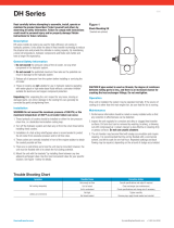
Condensate drainage
The droplet collectors installed in the cooling and heat recovery sections are equipped with drain pipes through which the
condensation is removed outside the unit. Connect the U-trap to the outlet pipe. The U-trap and the droplet separator must be
equipped with a freeze protection.
The U-trap dimensions depending on the size of the pressure in the section are stated in Table.
H
h
Total Fan Pressure [Pa] Size H [mm] Size h [mm]
<600 100 50
600-1000 40 70
1000-1400 190 5
1400-1800 240 120
1800-2200 290 45
2200-2600 340 170
Fan connection
All the connections must be made in accordance with the technical specifications for the automatic control system.
The electric power supply must comply with the following specifications:
• Voltage: voltage within 0.9 ...1.1 of the rated value;
• Frequency: 0.99…1.01 of the nominal frequency at all times and 0.98…1.02 at peak times.
M
U V
L1 L2
L3
W PE
PE
0-10 Gndnc com
M
U V W PE
PE
M
U V
L N
PE
PE
0-10 Gnd
+10V
+10V
nc com
L1 L2 L3
0-10 Gndnc com
M
U V PE
PE
0-10 Gnd
+10V
+10V
nc com
L N
АС-motor
ЕС-motor
Control
Alarm
relay
Control
Alarm
relay
3~400V 1~230V
3~400V
1~230V

www.ventilation-system.com
14
AirVENTS
The pressostat on the filter must be installed in such a way so
that its pipe marked with the (-) symbol is routed via a tube to the
lower pressure area (downstream of the filter) whereas the pipe
marked with the (+) symbol is routed to the higher pressure area
(upstream of the filter).
The pressostat on the fan must be installed in such a way so that
its pipe marked with the (-) symbol is routed via a tube to the
lower pressure area (upstream of the motor) whereas the pipe
marked with the (+) symbol is routed to the higher pressure area
(downstream of the motor).
Connection of pressostats
Electric heater connection
Air damper connection
M
N L1
3x0,75
L
N L1 L
M
N L
2x0,75
N L
Servoactuator of the air damper
without a return spring
Servoactuator of the air damper
with a return spring
L1 L2 L3
PE
3~400V
L1
L2
L3
PE
The electric heaters are equipped with overheat protection thermostats which activate at 50 °C
(automatic reset) and 90 °C (manual reset).
Wiring of the electric heaters is shown on the diagram on the right.

www.ventilation-system.com
15
STARTUP PREPARATIONS
The permanent operation must be preceded by start-up preparations.
Such a start-up must only be performed by the properly qualified and trained personnel.
Prior to the test run the personnel must study the instructions and schematic diagrams being part of the technical documentation of the
unit and perform the following steps:
• Check the unit for proper installation.
• Check all the ventilation devices for proper connection to the power supply.
• Make sure all the hydraulic and electrical connections are properly connected to the to the respective sections of the unit.
Electrical equipment
Check the electrical equipment for proper connection, insulation integrity and grounding against the electrical connections diagram
and the technical parameters of the components.
Further inspect the electric wires and the power consumers visually for insulation integrity.
The installation operations must comply with the provisions of the unit-specific technical documentation.
Any non-compliance of the installation work with the technical documentation shall void the manufacturer’s warranty for the unit.
If the installation has been performed by the manufacturer’s engineers, the electrical equipment and the entire unit shall be covered by
the identical warranty for the air handling unit.
Electric heaters
Make sure the heater is clean and intact.
Connect the heater in accordance with the wiring diagram.
The connected heater must not be in contact with other elements of the units.
Water heaters
Check the pipelines for proper connection (supply and return lines) and then inspect the condition of the heater plates.
Adjust the settings of the freeze protection thermostat (factory setting +5 °C) in succession as well as the tightness of the capillary
contact with the heater surface.
The heat medium control valve controlling the heater operation must be installed in accordance with the markings on the housing.
DX, water and glycol coolers
Check the condition of the cooler plates and the supply and return pipelines for proper connection.
Then check the droplet separator for proper installation relative to the air flow and then perform the same with regards to the U-trap.
Filters
Check the filters for proper attachment, their density and general condition.
The detailed filter specifications shall be checked against their respective documentation.
Cross-ow plate heat exchanger
Check the heat exchanger surface for any contamination and mechanical damage.
Check the droplet separator (if available) for proper installation relative to the air flow, and then perform the same with regards to the
U-trap. If the heat exchanger is equipped with a bypass, check the air shutters, dampers and electric actuator mounting.
Rotary heat exchanger
УMake sure that the heat exchanger cells are clean and free from damage.
Check the belt tension with the spring attached to the motor base and adjust it, if necessary. Check the control unit mount (if available).
Fan section
Check the fan section prior to starting the unit.
Make sure that the section is free from any foreign objects such as the yellow-colour transportation fasteners and assembly
components.
Failure to do so may result in the unit damage. The fan impeller must have a smooth running.
Then check the following:
• The electrical connections against the wiring diagrams.
• The fan motor for proper connection (the mains voltage must comply with that one on the motor rating plate).
• The ground wire for proper connection if the fan is mounted on rubber anti-vibration dampers.
• The rubber anti-vibration dampers in the fan section for proper installation.
• All the wires in the fan section for proper clamping.
If all the above steps are successfully completed, all the unit doors may be closed.

www.ventilation-system.com
16
AirVENTS
TEST RUN
AUTOMATION
The unit start-up preparations and the test run must only be performed by specially trained and duly qualified personnel.
Prior to starting the fans check the air dampers for proper operation.
Correct and safe operation of the unit is provided only in case of connection to designed ductwork system.
After the start-up let the unit run for approximately 30 minutes.
During the test operation measure the electrical equipment current and the unit air capacity.
Absence of elevated noise levels, abnormal noises or smells generated by the unit or vibration registered during the test run suggests
successful commissioning of the air handling unit.
If the results suggest otherwise, troubleshoot any malfunctions in the unit operation.
On registering any of the above phenomena disconnect the unit from power supply and double-check each of its sections.
After the unit power-off and before opening the panels make sure that the unit impeller has come to a full stop.
If this cannot be confirmed visually, do not open the panels until 3 minutes after the power-off.
If no malfunctions occur within a 30-minute test run the unit can be switched off and inspected. .
Inspect:
• The filter mounts;
• Condensate removal efficiency;
• Motor temperature and the condition of the fan group bearings.
Upon checking all the connections check the ant-vibration dampers for proper operation.
If allowed by the climatic conditions, check the freeze protection thermostat operation.
Such check may be carried out when the supply air temperature is lower than the thermostat temperature threshold.
Should this be the case temporarily shut off the heat medium supply to the heater at the supply air temperature of +1..2 °C.
Thermostat activation indicates its proper operation.
If the test run is performed during the warm season, check the thermostat operation at the earliest opportunity during the nearest cold
season.
Automation is an integral part of each supplied air handling unit. It enables smooth control and failsafe operation of the unit, prevents
possible operation problems and alarms.
This user’s manual contains no data or guidelines for mounting of the automation system components, connection, commissioning
and operation of the system.
This information is available is the supplied technical documentation for a delivered automation system type.
Otherwise the supplier of the automation system must provide the required information.
The control unit may be supplemented with extra controls like air damper actuators, frequency converters, pressure and temperature
sensors, CO2 sensors, constant air flow sensors, humidifiers, triac controllers.
Operation manuals for the automation system components are supplied separately.
OPERATION AND MAINTENANCE
The air handling units are designed for continuous operation.
Therefore, to ensure proper unit performance schedule periodic checks with special attention given to the life-limited parts such as
filters and bearings.
Filter replacement and cleaning are not be considered as warranty cases.
The basic technical details required for the regular inspection are given on the technical specification chart provided with each device.
The chart contains the view and dimensions of the essential elements such as filters, heat exchangers, fans and electric motors.
Filters
The air conditioning units are equipped with pocket and panel filters.
Combination and location of the filters depends on functional composition of the unit.
It is essential during filter replacement to use the filter with the identical filtration class.
Filter clogging reduces its capacity and decreases the unit performance.
The filter must be replaced if the filter pressure falls below the critical threshold.
Abnormal filter contamination levels may result in an increased air flow rate in the units which may eventually cause filter warping and
even fan damage.
During the filter replacement the units must be disconnected from power supply.

www.ventilation-system.com
17
The coarse filter replacement frequency mainly depends on the air pollution level.
Proper coarse filter operation significantly extends the useful life of the fine filters.
Electric terminals
The electric terminals of all the electrical parts of the unit require periodic checking and tightening to prevent contact scorching and
equipment malfunction.
Water heater
The water heater is equipped with a freeze protection thermostat as standard.
On heat medium supply shutoff or in case of an interruption in the unit operation with the ambient air temperature below + 4 °C the
heater must be drained of the heat medium (except using the 40 % glycol mixture).
Contamination of the heater surface reduces its performance.
Therefore, check the heater plates for contamination.
Dust on the heater plates may also contribute to air resistance increase.
Clean the heaters with a vacuum-cleaner on the air supply side, compressed air jet or washing with a mild water solution of neutral
detergents non-corrosive for the aluminium plates.
Electric heater
The electric heater contains open coils which may accumulate dust during the unit inactivity.
An extensive contamination may generate a smell of burned dust or, in the worst-case scenario, a fire upon the subsequent heater start.
Check regularly the technical condition and contamination levels of the heaters and electrical connection .
Only dry cleaning is allowed.
Water cooler:
The water cooler maintenance is identical to that of the water heater.
In addition check the cooler and droplet separator for any dirt as well as for the condensate drain pipe obstruction.
To remove contamination, clean the cooling coils with a mild water solution of a neutral detergent.
DX cooler
The operation and maintenance for the DX coolers are identical to those of the water heater and the water cooler.
Make sure that the DX cooler is disconnected from power supply before cleaning.
Failure to do so may result in an uncontrolled Freon pressure spike and cooling equipment damage.
Cross-ow heat exchanger
The heat exchanger maintenance includes checking the plates for contamination and its technical condition.
Clean the cross-flow heat exchanger with a vacuum-cleaner, compressed air jet or washing the air ducts with a mild water solution of a
neutral detergent non-corrosive to the aluminium surfaces.
Check the droplet separator condition (if available), the condensate drain pan and the condensate removal system.
If the heat exchanger is equipped with a bypass air damper, inspect the bypass damper actuator and check the stroke of the damper
shutter.
Rotary heat exchanger
While performing the rotary heat exchanger maintenance make sure to check the cell condition.
The surface must be free from any contaminations or mechanical damage.
Check the belt tensioning regulated by the spring mounted to the motor base.
Check the control unit mount (if available).
Clean the rotary heat exchanger with a vacuum-cleaner, compressed air jet or washing the air ducts with a mild water solution of a
neutral detergent non-corrosive to the aluminium surfaces.
Air damper and air shutter
Check the air dampers periodically.
The shutters and gears may accumulate dust, grease and other contaminants preventing proper operation of the dampers.
If present, remove contamination with compressed air jet.
If such actions fail, subject the damper to a high-pressure wash with a water solution of a detergent non-corrosive to the aluminium
surfaces.
Ventilation equipment maintenance regulation
Component name
once a
week
once per
month
every 6
months
once a
year
1.
Supply lter*:
Inspection of the condition - + - -
Dust removal, compressed air jet - (!) + -
Replacement - - - +

www.ventilation-system.com
18
AirVENTS
Component name
once a
week
once per
month
every 6
months
once a
year
2.
Extract lter*:
Inspection of the condition - + - -
Dust removal, compressed air jet - (!) + -
Replacement - - - +
3.
Control switchboard:
Check-up of communication lines and power cables for integrity - + - -
Check-up of terminal connections - + - -
Check-up of launch protection equipment - + - -
Checking controller operation, analysis of error log + - - -
Temperature sensor reading analysis + - - -
Verification of set parameters of the frequency converter - - - +
Verification of the temperature sensor readings + - - -
Operation checking of the frequency converter of the rotor drive - - - +
Operation checking of protective circuit - + - -
4.
Water heater:
Visual inspection - - + -
Cleaning and washing - - - +
Operation check-up of the 3-way heat medium control valve (if the system is filled with
heat medium) and the circulation pump
- - + -
5.
Electric heater:
Visual inspection - + - -
Cleaning - - + -
Check-up of the electric heating elements - - + -
6.
Water cooler:
Visual inspection - + - -
Cleaning (together with the droplet separator) - - - +
7.
DX cooler:
Visual inspection - + - -
Cleaning (together with the droplet separator) - - - +
8.
Cross-ow heat exchanger:
Visual inspection - + - -
Check-up of the drain pan - + - -
Check-up of the drain system and U-trap - + - -
Check-up of the bypass damper and damper actuator - + - -
Heat exchanger cleaning - - +
9.
Rotary heat exchanger:
Check-up of the rotor smooth rotation - + - -
Check-up of the belt condition and tightening - + - -
10
Exhaust/Supply air shutters:
Check-up of the shutters smooth operation - - + -
Checking of the electric actuator and electric connections - - + -
Damper cleaning - - + -
11.
Back airow damper with shutters
Checking air shutters for smooth operation - - + -
Checking of the electric actuator and electric connections - - + -
Damper cleaning - - + -
12.
Supply and extract fans:
Visual inspection and check-up of the electric motors and impellers - + - -
Check-up of the motor fixation and vibration dampers on the mounting frame in the
fan section
- + - -
Check-up of the terminal connections in the motor terminal box - - + -
Test run of the motor with and without load - - + -
Checking of the impeller fixation to the motor shaft - + - -
Checking of the indirect motor heating temperature under the rated operation conditions - - + -
Current checking and measuring for each phase - - - +
Verification of the frequency converter parameters - - - +
Cleaning of the impeller and motor from dust - - + +

www.ventilation-system.com
19
ALARMS
Alarm Alarm source Possible troubles
1. Fire signalling
External signal from the fire alarm system.
The inputs of the external terminals are closed and the
alarm signal is generated.
Check the inlet circuits.
2. Supply fan
Operation signal from the supply fan frequency
converter.
Check the frequency converter settings.
Check the parameters of the controller inputs.
These parameters must be consistent with the frequency converter
parameters.
Fan pressostat.
Check the fan operation. Check the pressostat operation. Check the
thermostat capillary tube mounting.
3. Extract fan
Operating signal of the extract fan frequency
converter.
Check the frequency converter settings.
Check the parameters of the controller inputs.
These parameters must be consistent with the frequency converter
parameters.
4. Temperature sensor Malfunction of any temperature sensor
Check the current temperature readings in the controller menu, see
"Current status". If the controller reads the temperature -40 °C, it indicates a
short circuit in the corresponding sensor circuit. If the controller reads the
temperature +150 °C, it indicates a circuit breakdown.
5.
Heat exchanger
freezing
This alarm is generated if the temperature falls down
below the set point within a set time period.
Check the parameters of the control low for the heat exchanger.
Check the actuating device for operability.
Check the exhaust air temperature for operability.
6. Rotary heat exchanger
Operation signal from the rotary heat exchanger
frequency converter.
Check the frequency converter settings. Check the parameters of the
controller inputs. These parameters must be consistent with the frequency
converter parameters.
7. Heater freezing
Tripping of the freeze protection thermostat of the
heater. The freeze protection function is activated also
in the summer mode.
Set the thermostat tripping temperature from 8 to 10 °C.
Check the thermostat control circuit.
Check the settings of the operating contact for compliance.
8.
Low water
temperature
Low heat medium temperature at the end of the
heating cycle.
Check the heat medium.
Check the pump.
Check operation of the actuating device.
Check heat medium flow.
9.
Low return heat
medium temperature
Low heat medium temperature during operation.
Check the heat medium temperature.
Check operation of the circulation pump.
Check operation of the actuating device.
Check heat medium flow and make sure the hydraulic system is not
clogged.
10. Circulation pump No pump operation control.
Check the pump operability.
Check operability of the control unit (pressostat, flow rate sensor, etc.).
If a control unit is not available, jump the respective inputs.
11. Supply filter Supply filter clogging.
Check for clogging.
Check the clogging control device (pressostat).
12. Extract filter Extract filter clogging.
Check for clogging.
Check the clogging control device (pressostat).
13. Heater overheating Tripping of the overheating thermostat.
Check the supply air damper for opening, check the supply filter for
clogging, check operability of the actuating device (relay).
14.
Low supply air
temperature
Low supply air temperature within 10 minutes
(scheduled) is interpreted as underheating.
Check the heating element and control circuit condition.
Make sure that the environmental conditions of the installation place match
the stated conditions.
((!) — more intensive contamination requires more frequent applications.
*— filter cleaning and replacement frequency may vary depending on the region and air pollution degree.

www.ventilation-system.com
20
AirVENTS
TROUBLESHOOTING
Problem Possible source. Troubleshooting method
1.
Filter alarm (clogging).
Filter clogging.
Clean the filter using a vacuum cleaner against air flow direction or install a
new filter.
(!) Do not wash the filter with water or detergents!
Malfunction of the pressostat or breakdown of the
commutation circuit (NC - normally closed contact).
Check the status of the pressostat or check its circuit (NC - normally closed
contact).
2.
Low air flow.
Filter clogging, heater or heat exchanger
contamination.
Clean the fan, the heater and the heat exchanger.
Fan malfunction. Check power supply to the fan. Check the control system for errors.
One or two air dampers are closed.
Check the air damper for smooth opening.
Check connection to power supply and available control signal on the
damper actuator.
Wrong rotation direction of the fan.
Check the three-phase motor for correct phase sequence.
Check the capacitor capacity and its status for the single-phase motor.
(!) The rotation direction is shown on the impeller of the ventilation unit.
3.
Water dripping in the
unit.
Drain line clogging. Clean the pipes.
No U-trap. Install the U-trap.
Wrong unit-drain line mounting angle.
Check the installation angle of the air handling unit/drain line for
consistence with the data stated in the technical documentation. Correct it
if required.
4.
No heating (applicable
for the air handling
units with an
integrated heater)
No power supply to the electric heating elements.
Check power supply to the heater section.
Check resistance of each heating element and check them for integrity.
In case of any breach on the circuit of the heating element replace it.
Tripping of the thermal switch TK 90 °C.
Press the button ""Reset"" on the thermal switch TK90 for manual reset.
(!) Troubleshoot the tripping source for TK90.
No contact on the electric heating elements. Press the connection lugs of the heating elements.
Breaking of the electric heater element (wire breaking) Replace the electric heating element.
Breakdown of the solid-state relay.
Check the condition of the solid-state relay using a volt-ohm meter.
Normally the relay does not acts as a conductor and is closed.
5.
Water heater/cooler
has insufficient heating
or cooling capacity.
No heat medium.
Check availability of the heat medium in the hydraulic system, its
temperature and pressure.
Air locks in the hydraulic system. Deaerate the system.
No heat medium circulation.
Check power supply to the circulation pump.
Check the pump rotor for rotation.
Malfunction or closing of the mixing unit.
Check power supply to the mixing unit actuator.
Check the connection of the actuator to the actuating device.
Open bypass damper.
Check the bypass damper actuator for jamming. Make sure it is properly
connected to power supply and the bypass damper opening procedure
matches the control system command.
6.
Abnormal noise
generated by the unit.
Direct connection of the air duct to the casing without
anti-vibration connector.
Do not allow the air duct to be connected directly to the unit.
Run-out of the motor bearing service life.
Check rotation of the rotor with idle running. Noise and skirr may indicate
the run-out of the bearing service life.
7.
Malfunction of one or
two motors.
No power supply to the electric motors. Check the voltage.
Motor winding breakdown or turn-to-turn short circuit
of the motor winding.
Check resistance of each motor winding using a volt-ohm meter.
No control signal for EC motors.
Make sure the signal is available for specified status of the control system
parameters. Check the control system for errors.
/