GE CDT725SSF2SS Installation guide

Category
Dishwashers
Type
Installation guide
Installation Instructions
Built-in Dishwasher
Ifyou have questions, call 800.GE.CARES(800.432.27371or visit our Website at: GEAppliances.com.
InCanada, please call 1.800.561.3344or visit www.geappliances.ca
BEFOREYOU BEGIN
Read these instructions completely and
carefully.
IM PORTANT - Observeallgoverningcodesand
ordinances.
, Note to Installer - Be sure to leave these instructions for the
consumer's and local inspector's use.
, Note to Consumer - Keep these instructions with your
Owner's Manual for future reference.
Skill Level - Installation of this dishwasher requires
basic mechanical, electrical and plumbing skills. Proper
installation is the responsibility of the installer. Product
failure due to improper installation is not covered under
the GE Appliance Warranty. See warranty information.
Completion Time - 1 to 3 Hours. New installations require
more time than replacement installations.
IM PORTANT - The dishwasherMUST be installed
to allow for future removal from the enclosure if service is
required.
Core should be exercised when the appliance is installed or
removed, to reduce the likelihood of damage to the power
supply cord.
If you received a damaged dishwasher, you should immediately
contact your dealer or builder.
Optional Accessories - Seethe Owner's Manual for available
custom panel kits.
FOR YOUR SAFETY
Read and observe all CAUTIONSand WARNINGSshown
throughout these instructions. While performing
installations described in this booklet, gloves, safety glasses
or goggles should be worn.
READ CAREFULLY.
KEEP THESE INSTRUCTIONS.
31-31524-1 09-13 GE
Installation Preparation
PARTS SUPPLIED
IN INSTALLATION PACKAGE:
, Junction box cover and #10 hex-head screw
, Hoseclamp
, Drain hose (approximately 78" long)
Drain hose hanger
2 #8-18 hex head screws to secure brackets to washer
tub frame
,1 top trim piece (onsome models)
,2 side trim pieces
,2 mounting brackets for wood countertops or side
cabinets
2 #8-18 x 5/8" Phillips special head screws, to secure
dishwasher to underside of countertop or to side
cabinets
Literature, samples and/or coupons
Junction
Box Cover
?
#10
Hex-Head
Junction
Box Screw
1/2" long
@
Hose Clamp
Drain Hose Hanger
Top Trim Piece
(on some models)
Mounting
Brackets
#8 Phillips
Special
Head Screws
5/8" long Literature
MATERIALS YOU WILL NEED:
. 90° elbow (3/#'hose internal thread on one end,
opposite end sized
to fit water supply)
, UL-listed wire nuts (3)
Masking Tape
%
90°Elbow
Wire Nuts (3)
Masking Tape
(if applicable)
Materials Needed for New Installations:
Air gap for drain hose, if required
Waste tee for house plumbing, ifapplicable
Electrical cable or power cord depending on your
model, quick connect power cords are availble.
Screw-type hose clamps
Strain relief for electrical connection
Hand shut-off valve (recommended)
Hot Water Line-3/8" minimum, copper tubing
(including ferrule, compression nut) or GEPart #
W×28×326, flexible braided hose.
GPF12or WD24×10065 drain hose (12'long), if needed
Waste T_ee
Air Gap
Strain Relief
Hand
Shut-Off
Valve
Electrical Cable
(or Power Cord, if applicable)
Hot Water Line
Drain Hose
??
#8 Hex-Head Mounting
Bracket Screws
Side Trim Pieces
Hose Clamps
Optional
12' Drain Hose
GPF12 or
WD24×10065
TOOLS YOU WILL NEED:
Phillips-head screwdriver
, 1/4" and 5/16" nutdriver
, 6"Adjustable wrench
, Level
, Carpenter's square
, Measuring tape
, Safety glasses
, Flashlight
, Bucket to catch water when flushing the line
, 15/16" socket (optional for skid removal)
, Gloves
, Pliers
For New Installations Only:
Tubing cutter
Drill and appropriate bits
Hole saw set
Phill2ad_
Screwdriver
15/16" Socket
Flashlight
Gloves
1/4" and 5/16"
Nutdriver
Pliers
Adjustable
Wrench
Bucket
Level
Carpenter's
Square
Tubing Cutter
Safety Glasses
Hole Saw Set
Measuring Tape
Installation Preparation
PREPARE DISHWASHER ENCLOSURE
33-1/2" to 34-3/4"
Underside of
Countertop
to Floor
ThisWallArea
mustbe Free
of Pipesor
wires
Zabinets
Square
and
Plumb
Figure A
, The rough cabinet opening must be at least 2/4"deep, 2/4"
wide and approximately 34-1/2" high from floor to underside
of the countertop.
kWARNING:
Toreducethe riskofelectricshock,fire,or injuryto persons,the
installermustensurethat the dishwasheriscompletelyenclosed
at thetime of installation.
The dishwasher must be installed so that drain hose is no
more than 12' in length for proper drainage.
The dishwasher must be fully enclosed on the top, sides and
back, and must not support any part of the enclosure.
CLEARANCES:
When installed into a corner,
allow 2" min. clearance
between dishwasher and
adjacent cabinet, wall or other
appliances.Allow 28-5/8" min.
clearance from the front
of the dishwasher for door
opening. Figure B.
Allow at least 6" between
dishwasher and range or
oven appliances.
iL
/ Countertop
ii _ishwasher
1-
28-5/8"
L Clearance for Door
Opening 2" Minimum
Figure B
DRAIN REQUIREMENTS
, Follow local codes and ordinances.
, Do not exceed 15' distance to drain.
NOTE:Air gap must be used, if waste tee or disposer
connection is less than 18" above floor to prevent siphoning.
DETERMINE DRAIN METHOD
The type of drain installation depends on the following
questions.
Do local codes or ordinances require an air gap?
Iswaste tee less than 18" above floor?
If the answer to either question isYES,Method 1 MUST
be used.
If the answers are NO,either method may be used.
CABINET PREPARATION
, Drill a 1-1/2" diameter hole in the cabinet wall within
the shaded areas shown in Figure A for the drain hose
connection. The hole should be smooth with no sharp edges.
IMPORTANT -When
connectingdrainlinetodisposer,
checktobesurethatdrainplughas
beenremoved.DISHWASHER WILL
NOT DRAIN IFPLUG ISLEFTINPLACE.
4 Remove
Drain
Plug
FigureC
Method 1 - Air Gap with Waste Tee or Disposer
An air gap must be used when required by local codes and ordi-
nances. The air gap must be installed according to manufacturer's
instructions.
DrainHoseHanger
Figure D
_ DrainHoseHanger
\
L
Method 2 - "High Drain Loop" with Waste Tee or Disposer
Tip: Avoid unnecessary service call charges.
Always be sure disposer drain plug has been removed before
attaching dishwasher drain hose to the disposer.
Installation Preparation
PREPARE ELECTRICAL WIRING
AWARNING:
FORPERSONALSAFETY:Removehousefuseor opencircuit breaker
beforebeginninginstallation.Donot useanextensioncordor
adapter plugwith this appliance.
_//_/_ / '_ Alternate
/ I
_ Receptacle
Location
I \
I \
Electrical Requirements
, Thisappliance must be supplied with !20V, 60 Hz.,and
connected to an individual properly grounded branch circuit,
protected by c]15- or 20-ampere circuit breaker or time-delay
fuse.
, Wiring must be2 wire with ground and rated for 75°C(!67°F).
, If the electrical supply does not meet the above requirements,
call c]licensed electrician before proceeding.
Grounding Instructions-Permanent Connection
This appliance must be connected to c]grounded metal,
permanent wiring system, or an equipment-grounding
conductor must be run with the circuit conductors and be
connected to the equipment-grounding terminal or lead on
the appliance.
Grounding Instructions-Power Cord Models
This appliance must be grounded. In the event of c]malfunction
or breakdown, grounding will reduce the risk of electric shock
by providing c]path of least resistance for electric current.
This appliance is equipped with c]cord having tin equipment-
grounding conductor and c]grounding plug. The plug must
be plugged into tin appropriate outlet that is installed and
grounded in accordance with all local codes and ordinances.
WARNING:
Theimproperconnectionof theequipmentgrounding conductor
can resultin a riskofelectricshock.Checkwith a qualified
electricianor servicerepresentativeifyou are indoubt that
the applianceisproperlygrounded.
Cabinet
Figure E White
For models equipped with power cord: Donot modify the plug
provided with the appliance; if it will not fit the outlet, have c]
proper outlet installed by c]qualified technician.
Cabinet Preparation & Wire Routing
, Thewiring may enter the opening from either side, rear or the
floor within the shaded area illustrated above in Figure Eand
defined in Figure A.
, Cut c]1-1/2" maximum diameter hole to admit the electrical
cable. Edgesof hole should be smooth and rounded.
Permanent wiring connections may puss through the same
hole us the drain hose and hot water line, if convenient. If
cabinet wall is metal, the hole edge must be covered with c]
bushing.
NOTE:Power cords with plug must puss through c]separate
hole.
Electrical Connection to Dishwasher
Electrical connection is on the right front of dishwasher.
, For permanent connections the cable must be routed us
shown in Figure E.Cable must extend c]minimum of 24" from
the rear wall.
, For power cord connections, install a 3-prong grounding
type receptacle in the sink cabinet rear wall, 6" min. or 18"
maximum from the opening, 6" to 18" above the floor.
, Use the Power Cord Kitfor your dishwasher model.
Installation Preparation
PREPARE HOT WATER LINE
NOTE:GErecommends copper tubing for the water line, but if
you choose to useflexible hose, use GE'sW×28×326, flexible
braided hose.
. Thewater supply line (3/8" copper tubing or flexible braided
hose) may enter from either side, rear or floor within the
shaded area shown in Figure F.
. Thewater supply line may pass through the same hole as the
electrical cable and drain hose. Or,cut an additional 1-1/2"
diameter hole to accommodate the water line. If power cord
with plug is used, water line must not pass through power
cord hole.
ACAUTION:
Do not remove wood base until you are ready to install the
dishwasher. The dishwasher will tip over when the door is
opened if base isremoved.
il Shut-off_
Hot
From
Cabinet
Cabinet
2" From Floor
Figure F
Water Line Connection
. If using a flexible braided supply hose, label the hose with the
installation date to use as reference. Flexible braided hoses
should be replaced in 5 years.
. Turn off the water supply.
. Install a hand shut-off valve in an accessible location, such
as under the sink. (Optional, but strongly recommended and
may be required by local codes.)
. Water connection is on the left side of the dishwasher. Install
the hot water inlet line, using no less than 3/8" copper tubing
or a flexible braided hose. Route the line as shown in Figure F
and extend forward at least 19" from rear wall.
. Adjust water heater for !20°F to !/40°F temperature.
. Flush water line to clean out debris.
. The hot water supply line pressure must be 20-120 PSI.
Turn page to begin dishwasher installation,
Dishwasher Installation
STEP 1:PREPARATION
Locate the items in the installation package:
, Screws
Junction box cover
Drain hose and clamp
Mounting brackets
Trim pieces (on some models)
Drain hose hanger
Owner's Manual
Product samples and/or coupons
STEP 2: CHECK DOOR BALANCE
/
NOTE:Ifinstalling a Cus-
tom Door Panel(available
on some models),please
follow the instructions
found in the Custom
Door Panel kit.
With dishwasher on
the wood base, check
the door balance by
opening and closing
the door.
Door /
closes /
within /
20 ° /
/
/ Door stays in
position from _ _-
20 ° to 70 ° _ _ "1_
_ _ _oor_ falls fully j
open beyond 70°_ "
Side View
I
. Door is properly F_g.roG
balanced if,when
opened, it self closes within 20° from vertical, stays in position
from 20°to 70° and falls fully open beyond 70°.
If necessary increase or decrease tension as shown. Some
models will have i spring on each side and other models will
have 2springs on one side and i spring on the other side.
Latch door and adjust springs to correct balance.
Side View
-- Custom
door
panel
Increase _nt View
Tension Spri
(_ Make sure pulley cables
hooked \_ / are within pulley shoulders
to screw \_ /
DecreaseTension inside leg
Figure H
Tip: Make sure door opens and closes smoothly.
Check door opening and closing. If door does not open easily or
falls too quickly, check spring cable routing. The cable is held in
place by "shoulders" on the pulley. Check to be sure cable has
not slipped over the pulley shoulders and isrouted as shown.
STEP 3: REMOVE WOOD BASE,
INSTALL LEVELING LEGS
IMPORTANT - Do not kickoffwood base!
Damage will occur.
Move the dishwasher close to the installation location and lay
it on its back.
Remove the 4 leveling legs on the underside of the wood base
with a 15/16" socket wrench.
. Discard base.
Figure I
. Screw leveling legs back into the dishwasher frame,
approximately 1/2" from frame as shown.
NOTE:Some models have rear adjustable leveling wheels, and
will not require the 2 rear leveling legs.
STEP 4: REMOVE TOEKICK
Removethe 2 toekick screws and toekick. Set aside for use in
Step 24.
Remove 2
Figure J Toekick Screws
STEP 5: POSITION SOUND BARRIER
(on some models)
Skip this step if the sound
barrier is not assembled
to the dishwasher.
Lift the sound barrier and
tape to the door front with
masking tape. This will
hold the sound barrier up
and out of the way during
installation.
Tape\_
Sound Barrier
Figure K
Bottom Front View
Dishwasher Installation
STEP 6:REMOVE FLOOR PROTECT
Squeeze connector at top
, Disconnect leak sensor wire to release snap feature
(on some models).
Remove 2screws from front of the
Floor Protect with a 1A"driver.
Rotate Floor Protect outward and lift
out of the mounting tabs.
Setaside for use in Step 22.
z_ Leak Sensor
J
f" Floor Protect
Figure L
STEP 7: INSTALL 90 ° ELBOW
. Thread 90° elbow
onto the water valve.
Do not overtighten Water Valve
elbow. Water valve Bracket
\
bracket could
bend or water valve
fitting could break.
Position the end of
the elbow to face the
rear of the dishwasher.
Front of dishwasher
90° Elbow
Figure M
STEP 8: INSTALL DRAIN HOSE TO DRAIN
LOOP
Connect drain loop end to drain hose using the screw clamp
as shown in the figure.
Figure N
NOTE:The high drain loop on the side of the tub is designed for
better wash performance. Do not remove from the side of the tub.
STEP 9: POSITION WATER LINE
AND HOUSE WIRING
Position water supply line and house wiring on the floor of
the opening to avoid interference with base of dishwasher
and components under dishwasher.
Line Wiring
Figure O
STEP 10: INSTALL DRAIN HOSE,
THROUGH CABINET
, Position dishwasher in front of cabinet opening. Insert drain
hose into the hole in cabinet side. If a power cord is used,
guide the end through a separate hole.
Maximum Drain Hose
Length 15'
Insulation ..
Blanket .._.
Hose
/
House
Wiring
\
PowerCord
(ifUsed)
Figure P
Tip: Prevent unnecessary service call charges for fill, drain
or noise concerns.
Position utility lines so they do not interfere with anything
under or behind the dishwasher.
Dishwasher Installation
STEP 11: SLIDE DISHWASHER THREE-FOURTHS
OF THE WAY INTO CABINET
IMPORTANT - Donotpushagainstfrontpanelwith
knees. Damage will occur.
Grasp the sides of the front panel and slide dishwasher into the
opening a few inches at a time.
Figure Q
Do not push against
front door panel with
knee. Damage to the
door panel will occur.
Asyou proceed, pull the drain hosethrough the opening under the
sink. Stop pushing when the dishwasher extends about 6 inches
forward of adjacent cabinets.
lake sure drain hose is not kinked under or behind the dishwasher.
lake certain the house wiring, drain line and water line do not
interfere with components under dishwasher.
STEP 12: INSTALL TRIM PIECES
In this step you will need the trim pieces set aside in Step !.
Top Trim
Side Trim
Figure R
4,"
Side
Trim
TopView
Side
Trim
Select the top trim piece (SeeFigure R)and line up center to the top
latch. Press the trim piece onto the tub flange moving from one side
to the other.
Select the left trim piece (seeFigure R).Aligntop edge with the top
trim and press it onto the left side of the tub flange moving from the
top to the bottom. Repeat for the right side tub flange trim piece.
(SeeFigure Rfor right side trim piece.)
STEP 13: INSTALL MOUNTING BRACKETS
You will need the mounting brackets and 2 #8 hex-head screws set
aside in Step !.
You must install the mounting brackets onto the dishwasher tub
frame top or sides prior to sliding the dishwasher into place under
the countertop. This dishwasher is capable of a true-flush installation
at a 24" deep opening. The mounting brackets have several
available attachment positions to accommodate different cabinet
constructions.
Install mounting brackets on top if the underside of
countertop is wood or wood-like materiel that accepts screws:
IMPORTANT - AfterinstaUingbracketsandbefore
closing the dishwasher door, adjust the brackets by bending
them up us needed, so that they do not contact the top of the
dishwasher door end cause damage.
Top Mounting
#8 Bracket __
Screw
Dis
tub frame
Bend and break here
after installing if
counter has a short
overhang.
Figure S
. Ifyou are installing the dishwasher under a counter with a short
overhang, the countertop brackets may extend beyond the edge
of the counter. If this isthe case, remove the excess length by
repeatedly bending the brackets at the front notch only until they
break.
Install mounting brackets on sides if the countertop is
granite or similar material that will not accept wood screws:
Break off front portion of the tab with pliers at the location shown.
Position the left-hand side bracket as shown. Repeat with the right
bracket.
Side Mounting
Dishwasher
tub frame
#8 Bracket
Screw as ------_%.
supplied ....
Figure T
////
Bendandbreak
Jhere if necessary
\i'-- _ Bracket
Dishwasher Installation
STEP 14: PUSH DISHWASHER INTO
FINAL POSITION
, Check the tub insulation blanket, if equipped, to be sure it is
smoothly wrapped around the tub. It should not be "bunched
up" and it must not interfere with the door springs. Ifthe
insulation is"bunched up" or interfering with the springs,
straighten and recenter the blanket prior to sliding the
dishwasher into its final position.
. Slidethe dishwasher into the final position by pushing on the
sides of the door panel. Do not use a knee or push on the
center of the panel. If you do, damage to the panel will likely
result.
IM PORTANT - Beforeopening the dishwasher door,
be certainthe edges of the dishwasher door panelare behind
the face ofthe adjacentcabinetand not up againstthe cabinet
face.Referto FigureU. Ifthe dishwasher door isopened
when the edge of the door isagainstthe face ofthe cabinet,
dishwasher door damage and cabinetdamage willoccur.
, Open and close the dishwasher door to be sure it operates
smoothly, and does not rub on the adjacent cabinet.
Door
Fits and
Swings
Back
Behind
Cabinet
Frame
Alignment
Figure U
Incorrect Alignment Door Catches
will result in door damage on Cabinet Frame
Tip: Prevent unnecessary service charges for panel damage
or wash performance.
Check dishwasher alignment prior to opening dishwasher door
to prevent panel damage.
Hake sure utility lines are not trapped or crushed behind
dishwasher. Crushed lines will restrict water flow.
STEP 15: LEVEL DISHWASHER
IM PORTANT - Dishwashermust be levelforproper
dishrackoper(]tion,w(]shperform(]nce(]nddoor oper(]tion.
The dishw(]shermust be leveledlefttoright(]ndfronttoback.
Thisensuresthedishrackswillnotrollinorout on theirown,
circul(]tion w(]ter will flow to the pump inlet, and the door will close
without hitting the side of
the tub.
Remove the lower dish rock ,,
(]ndplacea levelon the ,...................................................................
door (]ndlowerracktr(]ck
(isshown inFigureV.
Ifyour model has 4 leveling
feet,adjustthe levelofthe Check
dishwasherby individually
turningthe4 legson the Front Check
bottom ofthedishwasher to Back Level
/ Side
as illustrated in Figure W. _C; _toSide
If your model has rear
wheels, the height of the
\
wheels ore (]djusted from .....
the front of the dishw(]sher _' .......... J '_
.................................. /
(]long with the 2 front legs FigureV
on the bottom of the Adjust
dishw(]sher. Begin
the leveling process
with the front legs by
individually turning
the front 2 legs. By
(]djusting the front
legs first, (]ccess to
the re(jr leveling bolts
is m(]ximized easing
re(jr wheel
(]djustment.
When the
front legs
ore (]djusted
to (] height
resulting
in on
Figure W
(]ppropriate
gap to
the upper
cabinet, proceed to (]djust the re(jr leveling bolts (]nd wheels.
Individually turn the 2 bolts to (]djust the rear wheels. Slowly
rotate the 2 bolts counter clockwise to raise the dishwasher,
(]nd clockwise to lower it. Continue to (]djust the feet (]nd wheels
until the dishw(]sher is level (is illustr(]ted in Figure W.
The dishw(]sher is properly leveled when the level indic(]tar is
centered left to right (]nd front to b(]ck. Also, the dishw(]sher door
should close without hitting the side of the tub.
Repl(]ce the lower rock.
Pull e(]ch rock out, (]bout h(]lfway. Check to be sure it does not
roll back or forw(]rd on the door. Ifthe rock moves, (]djust
leveling legs.
Tip: Prevent unnecessary service charges. Verify dishwasher is
leveled.
Pull the dish rocks h(]lf w(]y out. They should st(]y put. Open (]nd
close the door. The door should fit in the tub opening without
hitting the side of the tub. If the rocks roll on their own, or the door
hits the side of tub, relevel the dishw(]she[
9
Dishwasher Installation
STEP 16: POSITION DISHWASHER, SECURE
TO COUNTERTOP OR CABINET
Inthis step you will need the 2 Phillipsspecial head screws
from the screws set aside in Step 1.
The dishwasher must be secured to the countertop or the
cabinet sides. When the underside of the countertop is wood,
use Method 1.Use Method 2 when the underside of the
countertop is made of a material, such as granite, that will not
accept wood screws.
IMPORTANT - Prevent door panel and control
panel damage. Dishwasher must be positioned so the front
panel and control panel do not contact the adjacent cabinets
or countertop. Mounting screws must be driven straight and
flush. Protruding screw heads could scratch the door panel or
control panel and interfere with door operation.
Method 1
Secure dishwasher to underside of wood countertop.
. Recheck alignment of the dishwasher in the cabinet. Referto
Steps 14 and 15. Door panel and/or control panel must not
hit cabinets or countertop.
. Fasten the dishwasher to the underside of the countertop
with the 2 Phillips special head screws. Referto figure.
Make certain screws are driven straight and flush to prevent
panel damage.
Brackets Wood Countertop
Method 2
Secure dishwasher to cabinet sides.
. Recheck alignment of the dishwasher in the cabinet. Refer
to Steps 14 and 15. Door panel and/or control panel must
not hit cabinets or countertop. Remove plug buttons. Do not
discard.
. Remove plug buttons. Do not discard.
. Fasten the dishwasher to the adjacent cabinets with the
2 Phillipsspecial head screws provided. Refer to Figure X.
Make certain screws are driven straight and flush to prevent
panel damage.
. Install plug buttons to the side of the tub in the holes
provided.
Solid Surface Countertop
_Scr_vs _ Plugbuttons
Figure ×
lo
STEP 17: CONNECT WATER SUPPLY
Connect water supply line to 90° elbow.
If using a flexible braided hose connection:
. Attach nut to 90° elbow using an adjustable wrench.
If using a copper tubing connection:
. Slide compression nut, then ferrule over end of water line.
. Insert water line into 90° elbow.
. Slideferrule against elbow and secure with compression nut.
IMPORTANT - Checktobesurethatdoorspring
and/ordoorspringcabledo notruborcontactthefillhoseor
water supply line.
Test by opening and
closing the door.
Reroute the water
supply lines if a
rubbing noise or
interference
occurs.
Hot Water
Supply Line
_,, X Compression
90° L_OOW X Nut
Ferrule
Figure Y
Bottom Left Side
STEP 18: CONNECT DRAIN LINE
The molded end of the drain hose will fit 5/8" through 1"
diameter inlet ports on the air gap, waste tee or disposer.
. Determine size of inlet port.
. Cut drain hose connector on the marked line, if required,
to fit the inlet port.
Figure Z
Cutting Line
/
/
IMPORTANT: Do not cut corrugated
portion of hose
. If a longer drain hose is required and you did not purchase
drain hose GPF12or WD24×10065, add up to 66" length for a
total of 144" (12 feet) to the factory-installed hose. Use 5/8" or
7/8" inside diameter hose and a coupler to connect/
the 2 hose ends.
Secure the
connection
with hose
clamps. Coupler Hose Clamp
Figure AA Hose Clamp
NOTE: TOTAL DRAIN HOSE LENGTH MUST NOT EXCEED 15 FEET
FOR PROPER DRAIN OPERATION.
Dishwasher Installation
STEP 18: CONNECT DRAIN LINE (Cont.)
. Connect drain line to air gap, waste tee or disposer
using the previously determined method. Secure hose
with a screw-type clamp.
Method 1 - Air gap with waste tee or disposer
Waste Tee Installation
Disposer Installation
Figure AB
Method 2 - "High drain loop" with waste tee or disposer
With this method you will need the drain hose hanger set aside
in Step !.
Fasten drain hose to underside of countertop with the provided
hanger.
__ Drain Hos,e Hanger
WasteTeeInstallation
Figure AC
DisposerInstallation
IMPORTANT - When connecting drain line to
disposer, check to be sure that drain plug has been removed.
DISHWASHERWILL NOTDRAINIF PLUGISLEFTIN PLACE.
4 Remove
Drain
Plug
Tip: Avoid unnecessary service call charges for a no drain
complaint.
Make sure excess drain hose has been pulled through
the cabinet opening. This will prevent excess hose in the
dishwasher cavity from becoming kinked or crushed by the
dishwasher.
STEP 19: CONNECT POWER SUPPLY
Ifa power cord with plug is already installed proceed to
Step 20.
AWARNING:
If housewiring isnot 2-wirewith ground,a groundmust be
providedbythe installer.Whenhousewiring isaluminum,be sure
to useUL-Listedanti-oxidantcompoundand aluminum-to-copper
connectors.
In this step you will need the junction box cover and the
#10 Hex head screw from the screws set aside in Step 1.
. Secure house wiring to the back of the junction box with a
strain relief.
. Locate the 3 dishwasher wires, (white, block and green) with
the stripped ends coming out of the ACjumper. Use ULlisted
wire nuts of appropriate size to connect incoming ground to
green, white to white and black to black.
. Install the junction box cover using #10 hex head screw.
Check to be sure that wires are not pinched under the cover.
. Hake sure that the junction box cover is resting on the
mounting bracket.
. If using a Power Cord Kit, please refer to the included
instructions.
NOTE:Do not remove the
Junction Box Bracket.
Ground
White
AC
Figure AD
Black
@our Screws
Junction Box
Bracket
11
Dishwasher Installation
STEP 20: PRETEST CHECKLIST
Review this list after installing your dishwasher to avoid
charges for a service call that is not covered by your
wa r ra nty.
. Check to be sure power is OFF.
, Open door and remove all foam and paper packaging.
, Locate the Owner's Manual set aside in Step 1.
, Read the Owner's Manual for operating instructions.
. Check door opening and closing. If door does not open and
close freely, check for proper routing of spring cable over
pulley. If door drops or closes when released, adjust spring
tension. SeeStep 2.
. Check to be sure that wiring is secure under the dishwasher,
not pinched or in contact with door springs or other
components. See Step 19.
, Check door alignment with tub. If door hits tub, level
dishwasher. SeeStep 15.
, Check door alignment with cabinet. If door hits cabinet,
reposition dishwasher. See Step 1/4.
, Check that door spring does not contact water line,fill hose,
wiring or other components. See Step 1/4.
, Verify water supply and drain lines are not kinked or in
contact with other components. Contact with motor or
dishwasher frame could cause noise.
STEP 21: DISHWASHER WET TEST
,Turn on power supply or plug power cord into outlet,
if equipped.
, Select a cycle to run and push the Start button.
, Ensurethe door is latched. Dishwasher should start.
, Check to be sure that water enters the dishwasher. If water
does not enter the dishwasher, check to be sure that water
and power are turned on.
, Check for leaks under the dishwasher. If a leak isfound, turn
off power at the breaker, and then tighten water connections.
Restore power after leak is corrected.
, Check for leaks around the door.A leak around the door could
be caused by door rubbing or hitting against
adjacent cabinets. Reposition the dishwasher if necessary.
SeeStep 14.
Pressand hold the Start button for 3 seconds to cancel
the cycle.The unit will begin to drain. Check drain lines. If
leaks are found, turn off power at the breaker and correct
plumbing as necessary. Restore power after corrections are
made. See Steps 8, 10, 11 and 18.
, Open dishwasher door and make sure all of the water has
drained. If not, check that disposer plug has been removed
and/or air gap is not plugged. Also check drain hose to be
sure it is not kinked underneath or behind dishwasher. See
Step !8.
,Turn on the sink hot water faucet and verify water
temperature. Incoming water temperature must be between
120°Fand 140°F.A minimum of 120% temperature is
required for best wash performance. See "Prepare Hot Water
Line,"page 5.
, Add 1 quart of water to the bottom of the dishwasher to
lubricate the pump seal.
,Turn on water supply. Check for leaks.Tighten connections if
needed.
, Remove protective film if present from the control panel and
door.
PressStart button once again and run dishwasher through
another cycle. Check for leaks and correct if required.
Repeat this step as necessary.
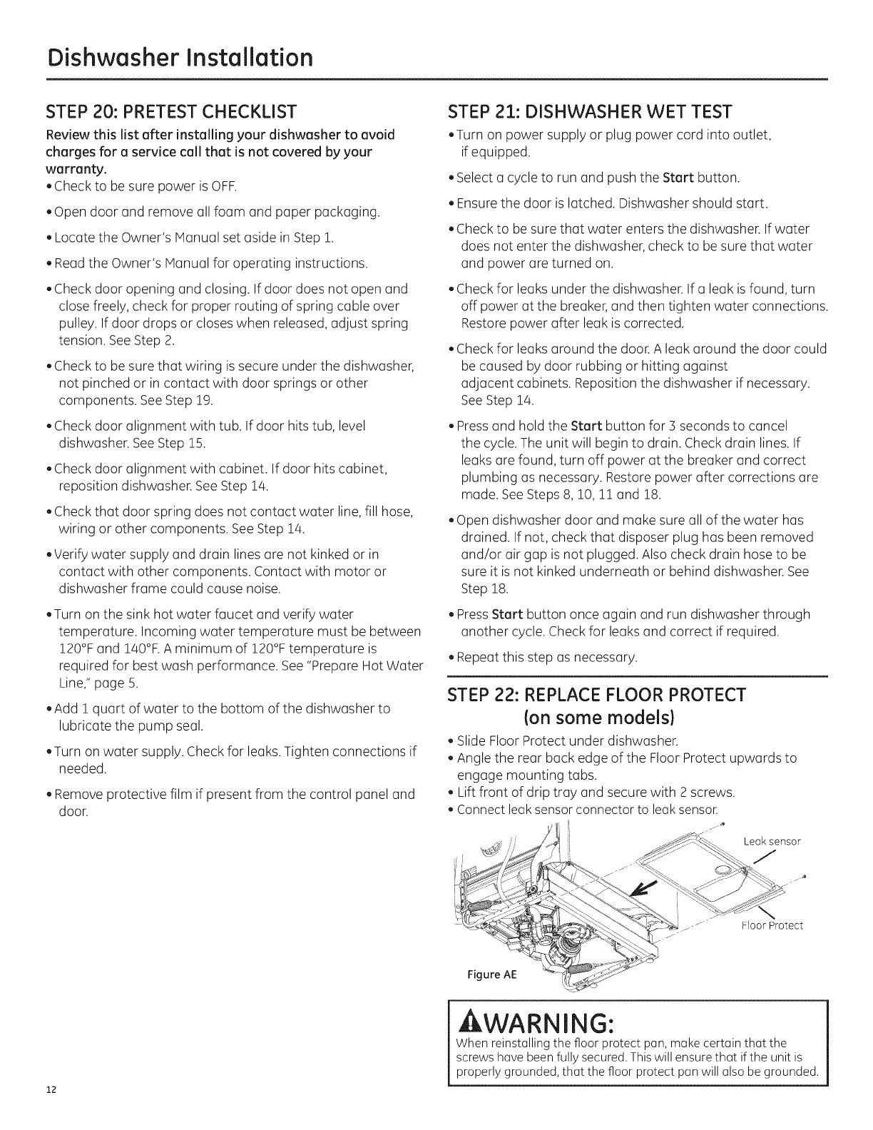
STEP 22: REPLACE FLOOR PROTECT
(on some models)
, Slide Floor Protect under dishwasher.
, Angle the rear back edge of the Floor Protect upwards to
engage mounting tabs.
, Lift front of drip tray and secure with 2 screws.
, Connect leaksensor connector to leaksenson
Leak sensor
Floor Protect
Figure AE
12
AWARNING:
Whenreinstallingthe floorprotect pan,makecertain that the
screwshavebeenfullysecured.Thiswill ensurethat ifthe unitis
properlygrounded,that the floorprotect panwill alsobe grounded.
Dishwasher Installation
STEP 23: POSITION INSULATION, PRE-
TOEKICK, AND SOUND BARRIER
Ion some models)
Skip this step if the sound insulation package is not supplied
with the dishwasher.
. Locate the sound insulation package and pre-toekick
packages inside the dishwasher.
, Stand the partSDishwasherUprightas......_._jshown. k,_
Door
O
, On models so equipped, remove the masking tape from the
sound barrier and door front. Position the sound barrier over
the insulation. Sound
Barrier
STEP 24: REPLACE TOEKICK
, Place toekick against the pre-toekick (on some models) and
legs of the dishwasher.
Toekick Sound barrier Pre-
{On some Toekick
models. Port is (Onsome
Figure AF already attached models.)
to door.)
. Locate the control box.
Control Box
o
Panel Insulation
(Onsome Block
models.) (Onsome
models.)
_:_ Figure AG 33_--
, Push insulation block portion under the dishwasher until it is
beneath the control box.
Figure AH
. Pushthe panel portion up to the front of the block.
4F
Push behind
the toekick ettechment screw holes
. Tuckthe sides of the front panel behind the toekick
attachment screw holes.
. Open door all the way, if the door doesn't stay fully open,
adjust the insulation panel.
. On models so equipped, position pre-toekick over the
insulation. Align the screw holes with the screw holes on the
legs of the dishwasher.
Figure AH Screws
Align the toekick with the bottom edge and make sure it is
against the floor.
Insert and tighten the 2 toekick attachment screws. The
toekick should stay in contact with the floor.
When reinstalling the toe kick on models with a sound barrier,
ensure that the bottom edge of the rubberized flap isflush
with the floor. Any excess material should be tucked up
behind the outer door. Donot allow excess rubberized flap to
lay on the floor. If any excess is not tucked completely behind
the outer door, it will bunch up between the door and toe kick
and impede proper opening and closing of the door. This will
be noticeable because the door will not stay fully open and
will spring up.
Tip: Reduce sound from under the dishwasher. Make sure
toekick is against floor.
STEP 25: LITERATURE
. Besure to leave complete literature package, these
Installation Instructions and product samples and/or coupons
with the consumer.
13
SPECIFICATIONS SUBJECT TO CHANGE WITHOUT NOTICE
GEAppliances
General Electric Company
Louisville, Kentucky/40225
GEAppliances.com
© 2013 General Electric Company
LES SPECIFICATIONS PEUVENT ETREMODIFII_ES SANS PREAVIS
GEAppliances
General Electric Company
Louisville, Kentucky/40225
www.electromenagersge.ca
© 2013 General Electric Company
ESPECIFICACIONES SUJETAS A CAPIBIOS SIN AVISO PREVIO
GEAppliances
General Electric Company
Louisville, Kentucky/40225
GEAppliances.com
© 201] General Electric Company
  • Page 1 1
  • Page 2 2
  • Page 3 3
  • Page 4 4
  • Page 5 5
  • Page 6 6
  • Page 7 7
  • Page 8 8
  • Page 9 9
  • Page 10 10
  • Page 11 11
  • Page 12 12
  • Page 13 13
  • Page 14 14
  • Page 15 15
  • Page 16 16
  • Page 17 17
  • Page 18 18
  • Page 19 19
  • Page 20 20
  • Page 21 21
  • Page 22 22
  • Page 23 23
  • Page 24 24
  • Page 25 25
  • Page 26 26
  • Page 27 27
  • Page 28 28
  • Page 29 29
  • Page 30 30
  • Page 31 31
  • Page 32 32
  • Page 33 33
  • Page 34 34
  • Page 35 35
  • Page 36 36
  • Page 37 37
  • Page 38 38
  • Page 39 39
  • Page 40 40
  • Page 41 41
  • Page 42 42
  • Page 43 43
  • Page 44 44
  • Page 45 45
  • Page 46 46
  • Page 47 47
  • Page 48 48

GE CDT725SSF2SS Installation guide

Category
Dishwashers
Type
Installation guide

Ask a question and I''ll find the answer in the document

Finding information in a document is now easier with AI