Page is loading ...

STAINLESS
STEEL
AND
PORCELAIN
5-BURNER
GAS
GRILL
Model number: GR2210601-MM-OO
ASSEMBLY
& OPERATING
INSTRUCTIONS
For
Outdoor Use
Only
• This instruction manual contains important information necessary for the
proper
assembly and safe use of the appliance.
•
Read and follow all warnings and instructions before assembling/using the
appliance.
• Failure
to follow these instructions and warnings could result
in
damage to the
product or injury to the user.
• Keep this manual for further reference.
Should you encounter any problem,
CALL US FIRST.
DO
NOT
return product to the retail store!!
WE CAN HELP.
For assistance, contact customer service at
or at (888) 837-1380, Mon to Fri, 8:00am - 5:00pm Pacific Standard time
1
of
36
20160928
Downloaded from www.Manualslib.com manuals search engine

WARNINGS
SAFETY
LABELS
Lt.OANGER:
Indicates
an
imminently hazardous situation which, if not avoided, will result
in
death
or
serious
injury.
Lt.WARNING:
Be
alert
to
the
possibility
of
serious
bodily
injury
if
the
instructions
are
not
followed.
Be
sure
to
read
and
carefully
follow
all
of
the
messages.
Lt.CAUTION:
Indicates a potentially hazardous situation, which, if -not avoided, may result
in
minor or moderate injury.
DANGER
If
you
smell
gas:
1.
Shut
off
gas
to
the
appliance.
2.
Extinguish
any
open
flame.
3.
Open
lid.
4.
If
odor
continues,
keep
away
from
the
appliance
and
immediately
call
our
gas
supplier
or
fire
department.
Failure
to
follow
these
instructions
could
result
in
fire
or
explosion
which
could
cause
propert
damage,
personal
in·ury
or
death.
WARNING
1.
Do
not
store
or
use
gasoline
or
other
flammable
liquids
or
vapors
in
the
vicinity
of
this
or
any
other
appliance.
2.
An
LP
cylinder
not
connected
for
use
shall
not
be
stored
in
the
vicinity
of
this
or
any
other
appliance.
DANGER
(a)
Do
not
store
a
spare
LP
gas
cylinder
under
or
near
this
appliance;
(b)
Never
fill
the
cylinder
beyond
80
percent
full;
(c)
If
the
information
in
(a)
and
(b)
is
not
followed
exactly,
a
fire
causing
death
or
serious
injury
may
occur.
PROP 65 WARNING
Chemicals
known
to
the
state
of
California
to
cause
cancer,
birth
defects
or
other
reproductive
harm
are
created
by
the
combustion
of
propane.
2
of
36
20160928
Downloaded from www.Manualslib.com manuals search engine

WARNING
• This outdoor cooking gas appliance shall be used only outdoors and shall not be used
in
a
building, garage or any other enclosed area.
• This outdoor cooking gas appliance is not intended to be installed
in
or on boats. This
appliance is not intended to
be
installed
in
or
on recreational vehicles.
•
Use your grill OUTDOORS
in
a well
ventilated
space away from dwellings
or
other buildings to prevent dangers
associated with gas
accumulation and toxic
vapors. The
gr
ill
should be situated at least
60
in
ches (152.4 cm) from buildings. Not
adheri
ng
to these clearances will prevent
proper
vent
il
ation and may increase the risk
of a fi
re
and/or property damage, which could
also result
in
personal injury.
• Maintain a minimum clearance of 60 inches
(152.4
cm
) between all sides of grill, deck
railings, walls or other combustible material.
Maintain a minimum clearance
of
60
DO NOT use grill under any overhead inches from combustible material.
combustible construction.
• DO NOT obstruct the flow of combustion/ventilation air.
• DO
NOT
leave the grill unattended while
in
use.
• DO NOT use while under the influence of drugs or alcohol.
•
Keep the fuel supply hose away from heated surfaces.
• DO
NOT
put the grill
in
storage or move
it
after use. Allow the grill to be cool to the touch
before moving/storing.
Failure to do so could result
in
a fire causing property damage,
personal injury or death.
• The appliance is for household use only. DO NOT use this grill for other than its intended
purpose.
• Never use natural gas
in
a unit designed for liquid propane gas.
• Never use charcoal or wood briquettes
in
a gas grill. Flavoring chips must be contained
in
a metal smoking box to contain ash and prevent fires.
• A Leak Test must be conducted prior to each use.
• Keep a fire extinguisher on hand acceptable for use with gas products. Refer to your local
authority to determine proper size and type.
• Grill is hot when
in
use.
To
avoid burns:
• DO NOT attempt to move the grill.
•
Lock the wheels so the unit does not accidentally move.
• Wear protective gloves
or
oven mitts.
• DO NOT touch any hot grill surfaces.
• DO NOT wear loose clothing or allow hair to come
in
contact with grill.
•
Never close the side burner lid during operation.
3
of
36
20160928
Downloaded from www.Manualslib.com manuals search engine

USE AND INSTALLATION OF LP GAS CYLINDER (PROPANE TANK)
BEFORE
INSTALLING:
The installation must conform with local codes or, in the absence of local codes, with either the
National Fuel Gas Code, ANSI Z223.1INFPA 54, Natural Gas
and
Propane Installation Code,
CSA 8149.1,
or
Propane Storage
and
Handling Code, 8149.2,
orthe
Standard for Recreational
Vehicles,
ANSI A 119.21NFPA 1192, and CSA Z240
RV
Series, Recreational Vehicle Code, as
applicable.
BEFORE EVERY USE:
8e
sure to inspect the hose for leaks, cuts, wear, abrasion,
or
damage of any sort before using
this appliance. If any damage is apparent, the hose must be replaced with a
new
hose specified
by the manufacturer before further use.
LP GAS CYLINDER
The LP (liquid propane) cylinder specifically designed to be used with this unit
MUST
have a 20
lb.
(9.1
kg) capacity with a Type 1 cylinder valve and an overfilling protection device (OPD). Only
use LP cylinders with this type of valve.
LP tank valve requirement:
• Purchase LP tanks only with these required measurements: 12"
(30.Scm) (diameter) x 18" (4S.7cm) (tall) with
201b.
(9kg) capacity
maximum.
• Type 1 outlet compatible with regulator
or
appliance.
•
Safety relief valve. OPD Hand Wheel
• UL-listed Overfill Protection Device (OPD). This
OPD safety feature
is
identified by a unique
LP
Tank
Valve
triangular hand wheel. Use only tanks equipped with
this type of valve.
• LP
tank must be arranged for vapor withdrawal.
Safety
Cap
The LP cylinder must be constructed and marked in
accordance with the Specifications for
LP-Gas
Cylinders of the U.S. Department of Transportation
(D.O.T.)
or
the National Standard of Canada
CAN/CSA - 8339, Cylinder, Spheres and Tubes for
Transportation of Dangerous Goods; and
Commission of Dangerous Goods; and Commission,
as
applicable.
•
The LP cylinder must include a collar to protect the cylinder valve.
• If the outdoor cooking gas appliance is not in use, the gas must be turned off at the supply
cylinder(s).
•
The LP cylinder must be stored outdoors out of the reach of children and
MUST
NOT
be
stored in a
building, garage, shed, breezeway,
or
any
other enclosed space.
• Storage of an outdoor cooking gas appliance indoors is permissible ONLY if the cylinder
is
disconnected and removed from the outdoor cooking gas appliance.
•
The cylinder should ALWAYS be put in an upright position.
4
of
36
20160928
Downloaded from www.Manualslib.com manuals search engine

DANGER
• DO NOT connect this grill to an existing #510 POL cylinder valve with Left hand threads.
The Type 1
valve can be identified with the large external threads
on
the valve outlet.
• DO NOT
connect to a propane cylinder exceeding its capacity.
• DO NOT connect
to
a cylinder that uses any other type of valve connection device.
• Never store a spare
LP
gas cylinder under or near your grill. This could cause pressure to
be
expelled through the vapor relief valve resulting
in
fire, explosion, or severe personal
injury, includi
ng
death.
• Keep the vent
il
ati
on
opening(s) of the
LP
gas cylinder enclosure free and clear from
obstructions and debris.
•
DO
NOT insert any foreign objects into the valve outlet. Damage to the valve outlet could
result.
A damaged valve outlet can cause a leak, possibly resulting
in
explosions, fire,
severe
bodily harm, or death.
WARNING
FOR FILLING THE
LP
GAS CYLINDER
• Allow only qualified
LP
gas dealers to properly fill or repair your LP cylinder.
• DO NOT allow
the cylinder to be filled beyond 80% capacity. Over-filled tanks can create a
dangerous condition.
Over-filled tanks can build
up
pressure and cause the relief valve to
expel propane gas vapors. The vapor
is
combustible and if it comes in contact with a spark
source or
flame an explosion causing severe burns, bodily harm, or death could occur.
• Always use a safety cap when the grill is not connected to a cylinder.
• If
you exchange a cylinder with a qualified exchange program, be sure the cylinder has a
Type 1
valve and
an
over-fill prevention device (OPO).
5 of
36
20160928
Downloaded from www.Manualslib.com manuals search engine

INSTALLING
GAS
CYLINDER
1.
Check that the cylinder valve is closed by turning the knob
in
clockwise.
2.
Pull out the cylinder holder along the slot.
3. Place the cylinder into cylinder holder and tighten the fixing bolt. Place cylinder such that the
valve opening faces the side burner
in
such a way that the hose is not kinked/damaged.
o
o
4.
Fix the cylinder holder
in
place and lock with the latch bracket.
~
\..I
(JJ
o
o
o
o
5.
Attach or detach the regulator to the LP gas cylinder only when the cylinder is placed on the
cylinder holder.
o
o
WARNING: Keep the fuel supply
hose away from any heated surfaces.
6
of
36
o
20160928
Downloaded from www.Manualslib.com manuals search engine

CONNECTION PROCEDURES
1.
Make sure the tank valve
is
closed (turn valve
clockwise until
tight).
2.
Check the tank valve to insure it has the
proper
external male threads.
3.
Make sure all burner valves are turned OFF.
4.
Inspect valve connections, port, and regulator
assembly.
Look for any damage or debris.
Remove any debris.
Inspect the hose for
damage. Never attempt to use damaged or
obstructed equipment. Contact your
local LP
gas
dealer for repair.
Tank
Valve/Knob
External Male
Threads
Coupling Nut
5.
When connecting the regulator assembly to the valve, hand tighten the quick coupling nut
clockwise to a complete stop. Do not use a wrench to tighten. Use of a wrench may damage
the quick
coupling nut and result
in
a hazardous condition.
6.
Open the tank valve fully (counterclockwise). Use a soapy water solution to check all
connections for leaks (a Leak Test) before attempting to light the grill (see P.26-27). If a leak
is
found, turn the tank valve off and do not use the grill until your
LP
gas dealer can make
repairs.
TO DISCONNECT
LP
CYLINDER:
1.
Turn the burner valves off.
2.
Turn the tank valve off fully (turn clockwise to stop).
3.
Detach the regulator assembly from the tank valve by turning the quick coupling nut
counterclockwise.
CAUTION
• When installing LP cylinders, the pressure regulator and hose supplied by the
manufacturer
MUST be used with the appropriate cylinder. Replacement regulators
and hoses need to be specified by the manufacturer of this appliance.
• Place
the dust cap on the cylinder valve outlet whenever the cylinder is not in use.
Only install the type of dust cap on the cylinder valve outlet that is provided with the
cylinder. Other types of caps or plugs may result
in
leakage of propane.
70f36
20160928
Downloaded from www.Manualslib.com manuals search engine


COMPONENT
LIST
1.
Warming
Rack
2.
Cooking
Grate
3.
Flame
Tamer
Qty:
1
pc
Qty:
3pcs
Qty:
5pcs
4.
Grill
Body
Assembly
5.
Side
Burner
Grate
6.
Side
Burner
Assembly
Qty:
1
pc
Qty:
1
pc
Qty:
1
pc
7.
Side
Burner
Control
Panel
8.
Control
Knob
Bezel 9.
Control
Knob
I
Side
Burner
Control
Knob
Qty:
1
pc
Qty:
1
pc
Qty:
1
pc
10.
Side
Table
Assembly
11.
Side
Table Panel
Assembly
12.
Grease
Cup
Qty:
1
pc
Qty:
1
pc
Qty:
1
pc
9
of
36 20160928
Downloaded from www.Manualslib.com manuals search engine

13.
Grease
Collecting
Tray
14.
Left
Cart
Side
Panel
Assembly
15. Tank Heat
Shield
Qty:
1
pc
Qty: 1
pc
Qty:
1
pc
16. Tank
Holder
Assembly
17.
Rear
Cart
Assembly
18.
Bottom
Cart
Panel
Qty: 1
pc
Qty: 1
pc
Qty: 1
pc
19.
Right
Cart
Side
Panel 20.
Front
Cart
Assembly
21.
Cart
Frame
Connecting
Tube
Qty: 1
pc
Qty: 1
pc
Qty:
4pcs
22.
Door
Handle
23.
Left
Door
Assembly
24.
Plastic
Insert
-
-
Qty:
2pcs
Qty:
1pc
Qty:
4pcs
10
of 36
20160928
Downloaded from www.Manualslib.com manuals search engine

25.
Right
Door
Assembly
26.
Locking
Caster
-
-
Qty
: 1
pc
Qty:
4pcs
HARDWARE
LIST
Item No. Item name
Diagram
Qty
A Phillips Head Screwdriver
('
~
~
1
B M4x10mm
Bolt (Black)
a--
4
C
M6x12mm Bolt (Black)
~
30
D Hex Nut Wrench
2:=
:3
1
E M4x10mm
Bolt (Silver)
au-
8
F M6x12mm Bolt (Silver)
~
24
G
LR6/
AA
Battery
I I
+p
1
H M4x8mm
Bolt
~
2
Note: Hardware H has been pre-attached on the
related components.
For
Bolt F, 16 pcs are stored in the hardware pack, and 8 pcs have been pre-attached on the
related components.
11 of 36
20
160928
Downloaded from www.Manualslib.com manuals search engine


Replacement Part List (II)
Part Part Name
Part
Part Name
Number
Number
1 Warming Rack
2 Cooking Grate
3
Flame Tamer
4
Grill
Body
Assembly
4a
G rill
Body
- Lid
4b
Grill Body -
Thermometer
4c
Grill Body -
Thermometer
Bezel
4d Grill Body - Lid Handle Bezel
4e
Grill
Body
- Lid Handle
4f Grill
Body
- Lid Support Left Bracket
4g
Grill Body - Fire
Box
4h Grill
Body
- Lid Support Right
Bracket
4i
Grill Body - Carry
Over
4j Grill
Body
- Burner
4k
Grill Body - Ignition Electrode & 4L Grill
Body
- Wood Chip
Tray
Wire
A
Channel
4m
Grill
Body
- Ignition Electrode & 4n Grill
Body
- Ignition Electrode &
WireB
WireC
40
Grill
Body
- Ignition Electrode &
4p
Grill
Body
- Wood Chip
Tray
Cover
Wire
0
4q Grill
Body
-
Wood
Chip Tray
4r
Grill
Body
- Fire
Box
Front Heat
Shield
4s
Grill
Body
- Valve & Manifold
4t
Grill
Body
- Control Panel
Assembly
4u Grill
Body
- Side Burner
Hook
4v
Grill
Body
- Hose & Regulator
Assembly
4w
Grill
Body
- Igniter
4x
Grill
Body
- Igniter Cover
4y
Grill
Body
- Burner Fixing Pin
4z
Grill
Body
-
Cotter
Pin
5
Side
Burner
Grate
6
Side
Burner
Assembly
6a
Side
Burner
- Lid
6b
Side
Burner
- Ignition Electrode
6c
Side Burner - Side Burner
6d
Side Burner - Side Burner Frame
6e
Side Burner - Ignition
Wire
7 Side Burner Control Panel
8
Control Knob Bezel
9 Control Knob / Side Burner Control
Knob
10
Side Table
Assembly
10a Side Table
10b
Side Table
Wire
Clip
11
Side Table Panel Assembly
11
a Side Table Panel
11
b
Name
Plate
12 Grease Cup
13 Grease Collecting Tray
14 Left Cart
Side Panel
Assembly
14a Left Cart Side Panel
14b Plastic Ring
15 Tank Heat
Shield
16 Tank Holder Assembly
16a Tank Left Sliding Bracket
16b Tank
Holder Base
16c Tank Right
Sliding Bracket
16d Tank Fixing
Screw
16e Tank Locking Plate
13 of 36 20160928
Downloaded from www.Manualslib.com manuals search engine

17 Rear Cart Assembly
17a Rear Cart Panel
17b
Rear Cart Frame
17c Match
Holder
18
Bottom Cart
Panel
19 Right Cart Side Panel
20
Front Cart Assembly 20a Front Cart Frame
20b Door Magnet Fixing Plate
21
Cart Frame Connecting Tube
22 Door
Handle 23
Left Door
Assembly
24 Plastic Insert 25
Right Door Assembly
26
Locking Caster
14
of
36
20160928
Downloaded from www.Manualslib.com manuals search engine

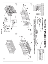
ASSEMBLY
PROCEDURES
Step
1.
Connect the Front Cart Assembly (20) and Rear Cart Assembly (17)
with 4 pcs Cart Frame Connecting Tube (21) then secure them with 8 pcs
M6x12 Bolts Black C .
Do
not full ti hten the bolts.
17
,
21
Step
2.
Attach the Left Cart Side Panel Assembly (14) to the cart assembly
usin 4 cs M6x12 Bolts Black C .
Do
not full
ti
hten the bolts.
14
14
15
of
36
20160928
Downloaded from www.Manualslib.com manuals search engine

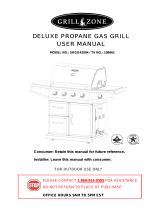
Step
3.
Attach the Right Cart Panel (19) to the cart assembly using 4 pes M6x12
Bolts Black
C.
Do not full
ti
hten the bolts.
c
19
19
Step
4.
Attach the Bottom Cart Panel (18) to the cart assembly using 10 pes
M6x12
bolts Black (C). Please follow the label at the bottom of the cart panel to
identif the rear osition.
Full
ti
hten all the bolts in the cart assembl .
C 18
16
of
36 20160928
Downloaded from www.Manualslib.com manuals search engine

Step
5.
Insert the Locking Casters (26) into the threaded holes on the bottom of
the cart
assembly. Use the Hex Nut Wrench
(0)
to tighten the caster by turning
in
clockwise until it
is
full secured.
D
Step
6.
Lock all 4 locking casters to prevent the unit moving by stepping the pad
downwards.
Slide the tank holder base from the Tank Holder Assembly (16)
then attach it to the cart
assembl usin 4 cs M6x12 bolts Black C as shown.
17
of
36
=
=
=
=
=
=
=
=
W
I
T
---
-
-
-
)
-"
-
--=-
-==-
=
=
=
=
=
=
=
=
-
-
..-
- t
I
'"
-
-
-
-
c
16
20160928
Downloaded from www.Manualslib.com manuals search engine

Step
7.
Attach the Left Door Assembly (23) and Right Door Assembly (25) to
the cart
assembl usin 8 cs M4x10 bolts Silver
E.
0
0
,-
/
~
,
~
.
,
//
,
~
~
0
~
~
'
0
E
,
~
/
23
25
Step
8.
Attach the Door Handles (22) to the doors with the Plastic Inserts (24)
usin 4 cs M6x12
bolts Silver F as shown.
F
18
of
36
20160928
Downloaded from www.Manualslib.com manuals search engine

Step
9.
Attach the Tank Heat
Shield
(15) to the cart assembly using 4 pcs
M4x10
bolts
Black
B.
15
;e::.
~
~
~
~
~
~
~
Step
10. This step needs two people to complete! Put the
Grill
Body
assembly
(4) carefully on top of the cart assembly. Secure the part
in
place as shown below
with 4 pcs of
M6x12mm
bolts
Silver
(F) as shown. Be careful to support the grill
bod and cart assembl durin this ste .
4
m
EAM
L FT
11
F
19
of
36
20160928
Downloaded from www.Manualslib.com manuals search engine

Step 11. Attach the Side Table Panel Assembly (11) to the Side Table
Assembl 10
usin 2 cs M6x12mm bolts Silver F .
11
Step 12. Loosen 4 pcs pre-attached bolts M6x12mm bolts Silver (F) on the right
side of the
grill body and adjust to 3/16" clearance as shown. Position the holes
on the side table assembly through the bolts at grill body as shown below. Push
the side
table assembly rightwards to lock it
in
place and tighten all bolts. Secure
the side table assembly to the control panel of the grill body assembly using 2
cs M6x12mm bolts Silver F .
~
)
"
3/16"
F
20
of
36
20160928
Downloaded from www.Manualslib.com manuals search engine
/