Page is loading ...

Owner's Manual
Liquid Propane GasGrill
Model 141.166400
Natural GasGrill
Modem141.176400
TM
//.vXk VVARNmNG:
Read this Owner's Manual carefully and besure your
gas grill isproperly assembled, installed and main-
tained. Failure to follow these instructions could
result in serious bodily injury and/or property dam-
age. This gas grill is intended for outdoor use only
and is not intended to be installed in or on
recreational vehicles or boats.
Note to Installer:
Leave this Owner's Manual with the consumer
after delivery and/or installation.
Note to Consumer:
Leave this Owner's Manual in a convenient place
for future reference.
Manufacturer's Customer Service Ne_pline:
if there are damaged or missing parts when you
unpack this unit from the shipping box, or you have
questions about assembly, call us 8am - 8pm CST,
Mondaythrough Friday at:
1-888-317-7642
Sears, Roebuck and Co.,
Hoffman Estates, RL60179 U.S.A.
P4799C- Rev: 11/2%2001

Warranty ..................................................... 2
Safety Instructions ..................................... 2
PreoAssembly Instructions ........................ 4
Hardware, Parts Diagram and Lists...5
Assembly Instructions ................................ 9
Lighting Instructions ................................. 16
Cleaning and Maintenance Instructions .. 18
Frequently Asked Questions ................. 20
Cooking Instructions ............................... 21
Cooking Guide and Recipes ............... 22
Full 1-Year Warranty on Grill
For one year from the date of purchase Sears will
repair or replace, at our option, any grill part
(except for paint loss and ignitor battery) that is
defective in material or workmanship.
Limited Warranty on Selected Gritl Parts
From one year after the date of purchase for the
designated time periods listed below, Sears will
replace the following grill parts if they are defective
in matedal or workmanship. You will be charged
for labor.
" Lifetime of Grill: Exterior Stainless Steel Parts,
Aluminum Castings (except for paint loss)
'_ 2 Years: Flame Tamers, Cooking Grids, Burners
,_ 4 Years: All Other Grill Parts (except ignitor battery)
Warranty Service
Warranty service is available by contacting your
nearest Sears Service Center.
Warranty Restrictions
,, This warranty is void if grill is used for commer-
cial or rental purposes.
" This warranty applies only when the grill is
used in the United States.
" This warranty gives you specific legal rights,
and you may also have other rights which vary
from state to state.
Sears, Roebuck and Co., Dept. 817WA,
Hoffman Estates, IL 60179
Combustion by-products produced when
using this product contain chemicals known
to the State of California to cause cancer,
birth defects, or other reproductive harm.
/_ WARNING
Failure to comply with these instructions
could result in a fire or explosion that
could cause serious bodily injury, death,
or property damage.
GrHI hstallation Codes
This gas grill must be installed in accordance with
all local codes. In areas without local codes,
follow the latest edition of the National Fuel Gas
Code ANSI Z223.1. In Canada, installation must
conform to standard CAN/CGA 1b149.1 or 1-
b149.2 (Installation Code for Gas Burning Appli-
ances and Equipment) and all local codes.
Correct LP Gas Tank Use
LP gas grill models are designed for use with a
standard 20 lb. Liquid Propane Gas (LP gas)
tank, not included with grill box. Never connect
your gas grill to an LP gas tank that exceeds
this capacity. A tank of approximately 12 inches
in diameter by 18-1/2 inches high is the maxi-
mum size LP gas tank to use. We recommend
buying an "OPD" gas tank which offers an
Overfill Prevention Device. This safety feature
prevents the tank from being overfilJed which can
cause malfunction of the LP gas tank, regulator
and/or grill.
The LP gas tank must be constructed and
marked in accordance with specifications of the
U.S. Dept. of Transportation (DOT). In Canada, the
LP gas tank must meet the Canadian Transporta-
tion and Communications (CTC)
specifications. Also be sure:
1. The LP gas tank has a shutoff valve, termi-
nating in an LP gas supply tank valve outlet,
that is compatible with a Type 1 tank con-
nection device. The LP gas tank must also
have a safety relief device that has a direct
communication with the vapor space of the
tank.
2. The tank supply system must be arranged
for vapor withdrawal.
3. The LP gas tank used must have a collar
to protect the tank valve.
2 @ Sears, Roebuck and Co.

Proper Placementand Clearanceof Gritl
Neveruseyourgasgrillinagarage,porch,shed,
breezewayoranyotherenclosedarea.Yourgasgrillis
tobeusedoutdoorsonly,atleast24inchesfromthe
backandsideof anycombustiblesurface.Your
gasgrillshouldnotbe placedunderany surface
thatwillburn.Donotobstructtheflowofventilation
air aroundthegasgrillhousing.
Thisoutdoorgasgrillisnotintendedtobeinstalledin
oronrecreationalvehiclesand/orboats.
Failureto complywith theseinstructions
could result in a fire or explosion that
could cause serious bodity injury, death,
or property damage.
,, Never connect an unregulated LP gas tank to
your gas grill. The gas regulator assembly
supplied with your gas grill is adjusted to have
an outlet pressure of 11" water column (W.C.)
for connection to an LP gas tank.
,, Only use the regulator and hose assembly
supplied with your gas grill. Replacement
regulators and hose assemblies must be those
specified by Sears.
,, Have your LP gas tank filled by a reputable
propane gas dealer and visually inspected and
re-qualified at each filling.
,, Never fill the gas tank beyond 80% full.
Have your propane gas dealer check the
release valve after every filling to ensure that it
remains free of defects.
,, Always keep LP gas tanks in an upright
position.
,_ Do not store (or use) gasoline or other flammable
vapors and liquids in the vicinity of this gas grill.
,, An LP gas tank that is not connected for use must
not be stored in the vicinity of this or any other gas
grill.
,_ Do not subject the LP gas tank to excessive heat.
,, Never store an LP gas tank indoors. If you
store your gas grill in the garage or other indoor
location, always disconnect the LP gas tank
first and store it safely outside.
,, LP gas tanks must be stored outdoors in a
weGventilated area. Disconnected LP gas tanks
must not be stored in a building, garage or
any other enclosed area.
,, When your gas grill is not in use the gas
must be turned off at the LP gas tank.
,, The regulator and hose assembly must be
inspected before each use of the grill. If there
is excessive abrasion or wear or if the hose is
cut, it must be replaced prior to the grill being
used again.
,, Keep the gas regulator hose away from
hot grill surfaces and dripping grease.
Avoid unnecessary twisting of hose. Visually
inspect hose prior to each use for cuts,
cracks, excessive wear or other damage.
If the hose appears damaged do not use the
gas grill. Call Sears at 1-800-4-MY-HOME for
a Sears authorized replacement hose.
,, Never light your gas grill with the lid closed
or before checking to insure the burner tubes
are fully seated over the gas valve orifices.
,, Never allow children to operate your grill. Do
not allow children to play near your grill.
A strong gas smell, or the hissing sound of
gas indicates a serious problem with your
gas grill or the LP gas tank. Failure to
immediately follow the steps listed below
could result in a fire or explosion that could
cause serious bodily injury, death, or prop-
erty damage.
Shut off gas supply to the gas gdll.
Turn the control knobs to OFF position.
Put out any flame with a fire extinguisher.
Open grill lid.
, Get away from the LP gas tank.
, Do not try to fix the problem yourself.
, If odor continues or you have a fire you
cannot extinquish, call your fire department.
Do not call near the LP gas tank
because your telephone is an electrical
device and could create a spark resulting
in fire and/or explosion.
CAUTION: Spiders and small insects occa-
sionally spin webs or make nests in the
grill burner tubes during transit and ware-
housing. These webs can lead to a gas flow
obstruction which could result in a fire in
and around the burner tubes. This type of
fire is known as a "FLASH-BACK" and can
cause serious damage to your grill and
create an unsafe operating condition for the
user.
Although an obstructed burner tube is not
the only cause of "FLASH-BACK", it is the
most common cause.
To reduce the chance of "FLASH-BACK",
you must clean the burner tubes before
assembling your grill, and at least once a
month in late summer or early fall when
spiders are most active. Also perform this
burner tube cleaning procedure if your grill
has not been used for an extended period
of time.

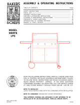
To reducethechanceof "FLASH-BACK"(see
CAUTIONon page3) cleantheburnertubesand
burnersbeforefullyassemblingyourgrill.Remove
the cotterpinfromtherearundersideof each
burnerusinga pairof longnosepliers.Carefully
lift eachburnerupandawayfromthegasvalve
orifice,thenreferto Figure1 andperformoneof
thesethreecleaningmethods:
1. Benda stiffwire,(a lightweightcoathanger
workswell)intoa smallhookasshownbelow.
Runthe hookthroughthe burnertubeand
insidetheburnerseveraltimesto removeany
debris.
2. Usea bottlebrushwitha flexiblehandle.Run
thebrushthroughtheburnertubeandinside
theburnerseveraltimes,removinganydebris.
3. Use an air hoseto forceair througheach
burnertube.Theforcedair shouldpassdebris
or obstructionsthroughtheburnerandoutthe
ports.
iF,,WARNtNG
The location of the burner tube with respect
to the orifice is vital for safe operation.
Check to ensure the orifice is inside of the
burner tube before using your gas grill. See
Fig. 2. If the burner tube does not fit over
the valve orifice, lighting the burner may
cause explosion and/or fire.
Figure 2
GASVALVE ASSEMBLY
ORIFICE BURNER TUBE
Figure 1
GAS COLLECTOR BOX
SPARK ELECTRODE ,_
ASSEMBLY \ BURNER
BURNER PORT
TO CLEAN BURNER TUBE,
INSERT HOOK HERE
................... OOT
/ COTTER PIN
BURNER TUBE
" Size 2 phillips screwdriver
'_ Size 4 phillips screwdriver
'_ Adjustable wrench
'_ Long nose pliers
'_ Open-end wrench, 11/16" size
', Protective work gloves
" Eye protection
4

Thefollowingtableillustratesa breakdownof thehardwarepack.it highlightswhatcomponentsareused
in thevariousstagesof assembly.
Ref. Component Qty.to Use
H005 1/4"xl/2"PhillipsHeadScrew 4
H008 1/4"Nut 4
H001 3/8"WheelBolt 2
H002 SpringWasher 2
H003 3/8"Nut 2
H005 1/4"xl/2"PhillipsHeadScrew 3
H008 1/4"Nut 3
H005 1/4"xl/2"PhillipsHeadScrew 7
H008 1/4"Nut 7
H005 1,"4"xl/'2"PhillipsHeadScrew 4
H008 1/4"Nut 4
H007 M4x6mmPhillipsHeadScrew 4
H006 1/4"x5/8"PartzThreadedBolt 4
H005 1/4"xl/2"PhillipsHeadScrew 2
H008 1/4"Nut 2
H005 1/4"xl/2"PhillipsHeadScrew 2
H008 1/4"Nut 2
H005 1/'4"xl/2"PhillipsHeadScrew 4
H012 1/4"xlz3/8"PhillipsHeadScrew 4
H009 1/4"LockNut 4
H004 1/4"x3/4"PhillipsHeadScrew 8
P0239A DoorHandle 2
P5589A MagneticDoorStop 2
P8080A AA Battery 1
H015 M6PhillipsHeadScrew 2
H016 M6Nut 2
H013 M18x1.5Nut 1
H014 M8x1.25Nut 1
PurposeofComponents
InstallBottomShelfTo CartLegs
InstallWheelsTo CartLegs
InstallRearPanelToCart
InstallTopPanelTo Cart
installDoorStopsTo Cart
InstallDoorHandlesTo Doors
InstallDoorsTo Cart
InstallPressureCylinderHolderTo Cart
(LPGonly)
InstallTankGuideTo Cart(LPGonly)
RestrictDrawerFromBeingPulledOutToo Far
InstallGrillHeadToCart
InstallSideShelfandSideBurnerTo Cart
InstallTo FrontDoors
InstallTo Cart
InstallTo ElectdcIgnitor
InstallToolHolderTo SideShelf
InstallPressureCylinderTo Holder(LPGonly)
InstallTankHookTo PressureCylinder
(LPGonly)

Actual Sizeand Quantity of Each Hardware Piece:
f-,
3/8" Wheel Bolt
Qty. 2 Spring Washer
Ref. # H001 Qty. 2
Ref. # H002
i' 'i
1/4"x3/4" Phillips 1/4"xl/2" Phillips 1/4"x5/8" Part-
Head Screw Head Screw Threaded Bolt
Qty. 8 Qty. 26 (4 for LPG) Qty. 4
Ref. # H004 Ref. # H005 Ref. # H006
Door Handle Part # P0239A
Qty. 2 Scale 1:2
3/8" Nut
Qty. 2
Ref. # H003
\\ i
\4
M6 Phittips Head Screw
Qty. 2
Ref. # H015(packed with
Tool Holder)
M4x6mm Phiitips 1/4" Nut 1/4" Lock Nut
Head Screw Qty. 22 Qty. 4
Qty. 4 Ref. # H008 Ref. # H009
Ref. # H007
Magnetic Door Stop Part # P5589A
Qty. 2 Scale 1:2
AA Battery Part # P8080A
Qty. 1 Scale 1:2
M18xl.5 Nut
Qty. 1 (for LPG)
Ref. # H013(attached
to Pressure Cylinder)
M8x1.25 Nut
Qty. 1 (for LPG)
Ref. # H014(attached
to Pressure Cylinder)
M6 Nut
Qty. 2
Refi # H016(packed
with Tool Holder)
\
1/4"xl-3/8" Philtips
Head Screw
Qty. 4
Ref. # H012

Remove all components from the packing carton and place within easy reach. Do not throw the shipping carton
away;
LPG = Liquid Propane Gas
NG = Natural Gas
instead use it as an elevated assembly surface.
4
6
1
3
25
48
49_
50 / 29
32
34
J
36
Y
37
Y
54
15
26
23
21 44
53 52 .....
46
(LPG only)
27
11
12
13
16
47 (LPG only)
55 j
35J
Y
35
4O
39
31
33
Y
43
(LPGonly)
(LPGonly)
41
'\ (LPG only)
\ 42
Y
j56
/57
/58
59 28
62
30a
(for LPG)
30b
"\\\ _ _ 61 _or NG)
38 60
(LPG only') (NG6o31y) -_

REF# DESCR_PT{ON PART# QTY REF# DESCR{PTION PART# QTY
1, Lid o Stainless Steel P0149F 1 43.
2, Lid Side Panel- Left P0145B 1 44.
3, Lid Side Panel- Right P0144B 1 45.
4, Temperature Gauge P0615D 1 46.
5. Name Plate P0459A 1 47.
6. Lid Handle P0237D 1 48.
Tank Guide (LPG only) P4033B 1
AA Battery P8080A 1
Heat°Insulating Spacer P5573A 2
Fuel Gauge Assembly (LPG only)P80F9B 1
Fixing Ring (LPG only) P80F9C 1
Tool Holder P55B6B 1
7. Stainless Steel Cooking Rack P1521B 1 49. Screw Cover
8. Cast iron Cooking Grid P1648B 2 50. Tool Hook
9, Stainless Steel Flame Tamer P1733A 2 51. Rain Shield
P55B6C 2
P55B6D 5
P80D5A 4
10. Burner Support Bracket P2218B 1 52. Rear Panel
11, Burner ° main P1935A 4 53. Top Panel of Cabinet
12, Gas Collector Box w/ Electrode P2618A 2 54. Front Door
P4327A 1
P1042B 1
P4328A 2
13, Ignition Wire Set P2626B 1 55.
14, Bowl Panel - Left P0751A 1 56.
15. Bowl Panel = Right P0752A 1 57.
16, Bowl Pane! o Rear P0732B 1 58.
17, Bowl Panel ° Front P0731B 1 59.
18. Heat Shield P2968A 1 60.
19. Gas Valve Assembly = main 4
LPG P32C1A
NG P32C2A 61.
Door Handle PO239A 2
Pot Support P80C6A 1
Side Burner Body - inner P2323B 1
Electrode Assembly P2627A 1
Burner Assembly o Side Burner P1920A 1
Gas Valve Assembly = Side Burner 1
LPG P3298E
NG P32C3A
Gas Valve Bracket P80C9A 1
20. Gas Manifold P5028A 1 62. Connection Tube P3983E 1
21, Electric Ignitor
22, Control Pane!
23, Control Knob
P2503C 1 63. NG 12' Hose Kit P3718A 1
P2957A 1 64. Air Shutter (NG only) P80C7A 4
P3430A 5 o=- Owner's Manual P4799C 1
24, Control Knob Seat P3430C 5
25, Storage Bin P1134A 1
26, Grease Draining Tray P2736A 1
27, Grease Receptacle P2717C 1
28, Insert Plate ° Stainless Steel P1131B 2
29, Side Shelf P1131E 1
o-- Hardware Pack (contents pg 5/6) P55E8A 1
If there are damaged or missing parts when you
unpack this unit from the shipping box, or you have
questions about assembly, ca[[us 8am z8pm CST,
Monday through Friday at:
1-888-317-7642
3Oa, Side Burner Body-outer (for LPG) P1137C 1
3Ob, Side Burner Body-outer (for NG) P1137B 1
31, Bottom Shelf of Cabinet P1042A 1
32. Cart Legs - Castor Side P0932A 1
33, Cart Legs - Wheel Side P0832A 1
34, Pulled°out Spice Tray P8078E 1
35, Magnetic Door Stop P5589A 2
36, Castor Seat P4521A 2
37, Castor P5109A 2
38, Regulator and Hose (LPG only) P3632L 1
39, Wheel Hub Cap - Graphite P5113C 2
40, Wheel - Graphite P5106D 2
41, Pressure Cylinder Guide P4033C 1
(LPG only)
42, Tank Hook (LPG only) P4033A
1
8
For the repair or replacement parts you need:
Call 6 am z11 pm CST, 7 days a week
1-800-366-PART
To make sure you obtain the correct replacement
parts for your Kenmore Elite gas grill, please refer
to the part numbers on this page. The following
information is required to assure you receive the
correct parts:
1. Grill Mode[ Number (see CSA label on grill)
2. Part Number
3. Part Description
4. Quantity of parts needed
Important: Keep this Owner's Manual for convenient
referral and for part replacement.
Important: Use only Sears authorized parts. The
use of any part that is not Sears authorized can
be dangerous and wi[[ void your product warranty.

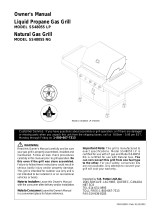
Beforeassemblingyourgasgrill,usetheparts
Figure1
listto checkthatall necessarypartsare included.
inspectallpartsfordamageasyouproceed.Donot
assembleor operateyourgrillif it appearsdamaged.
ifyouhavequestionsduringtheassemblyprocess,call
8am- 8pmCST,MondaythroughFriday,
1-888-317-7642
Remove the white PVC protective film from
stainless stee{ surfaces before assembly.
CAUTION:
While it is possible for one person to assemble
this gas grill, obtain assistance from another
person when handling some of the larger, heavier
pieces, especially the grill head.
Remove all cart parts, hardware, and grill head
from carton. Assemble the gas grill on a protective
work surface, such as the shipping box, to avoid
scratching surfaces. Refer to parts list and hard-
ware pack illustrations to help assemble your grill.
Assembling The Grill Cart
1. Position Bottom Shelf (Parts List item #31) with
its front vertical ledge facing down. Before
attaching Cart Legs to the Bottom Shelf, make
sure its 2 holes for Door Stop are located in
the front. See Fig. 1. Install the Cart Legs-
Castor Side on the left side of the Bottom
Shelf, with the Drawer Channel facing in. The
90 degree lip on sides and back of Bottom
Shelf must be on the outside of the Side
Panels for proper fit. Secure using 2 of the
1/4"xl/2" Phillips head screws and nuts pro-
vided. Install the Cart Legs-Wheel Side to the
other side of Bottom Shelf by using the same-
sized screws and nuts.
2. Install Rear Panel to inside of Side Panels using
3 of the 1/4"xl/2" Phillips head screws and nuts.
See Fig. 2.
3. Screw the 2 Castors into Castor Seats (see
bottom of Cart Legs=Castor Side). Turn threaded
castor stem by hand, clockwise until it stops.
Tighten with an Open=end 11/16" wrench. See
Fig. 2.
4. Install the 2 Wheels to the Cart Legs=Wheel
Side, by inserting the wheel bolt through the
wheel and axle hole on the cart leg as shown
in Fig. 2. Put spring washer and 3/8" nut onto
bolt and tighten securely using a size 4 phillips
screwdriver. Do not overtighten or wheel will not
turn freely. Snap Wheel Hub Caps onto wheels.
5. Position Top Panel (Parts List Item #53) with its
front vertical ledge facing up. Before installingthe
Top Panel, make sure its 2 holes for Door Stop
are located in the front. Place Top Panel into
position with 90 degree lip on outside of Rear
Panel. See Fig. 3. Secure firmly using 7 of the
1/4"xl/2" Phillips head screws and nuts provided.
DRAWER CHANNEL
CART LEGS
CASTOR
SEAT
HOLES FOR
DOOR STOP
Figure 2
BOTTOM SHELF
CABINET-
Parts List Item #31
iMPORTANT:
The 90 degree
lip of Bottom
Shelf should be
on outside of
Side Panel.
REAR PANEL
PANEL
CASTOR LJ
SEAT
CASTOR _'_WHEEL HUB
Figure 3
HOLES FOR
DOOR STOP
IMPORTANT:
The 90 degree
lip of Top Shelf
be on
outside of Rear
Pane!.
\TOP PANEL OF
CABINET-Parts
List Item #53
_SIDE PANEL

Assembling 1"he Cabinet Doors
1. Install Door Stops to Bottom Shelf and Top
Panel of Cabinet. See Fig. 4. Secure firmly
using 4 of the 1/4"xl/2" Phillips head screws
and nuts.
2. if you haven't already done so, remove the
white protective film from the stainless steel
Doors. Attach a Door Handle to each Front
Door using 2 of the M4x6mm Phillips head
screws provided. See Fig. 8. Be careful not to
scratch the door surfaces.
3. When installing the Front Doors, make sure
the door bolt holes are located on the hinge
sides of the Cart Legs.
4. Install either Front Door by inserting 1/4"x5/8"
part4hreaded bolt through the lower door bolt
hole of the Front Door and into the tapped
hole of the Bottom Shelf. Tighten securely.
Next, align the upper door bolt hole of Front
Door with the tapped hole in the Top Panel
of Cabinet. Insert 1/4"x5/8" part4hreaded bolt
provided and tighten securely.
5. Repeat these steps to install the other Front Door.
How To Level The Gritl Cart So The Doors Line-Up
When the top edge of the cabinet doors do not line-up
your grill cart needs to be leveled. This step is often
required after initial assembly and when your grill has
been moved to a new location. To level your grill cart,
use an 11/16" open-end wrench to unscrew either front
or rear Castor counterclockwise from its Castor Seat
(see bottom of the Cart Leg) until the cabinet doors are
aligned. See Fig. 5.
Figure 4
TOP PANEL
OF CABINET
HINGE SIDE
OF CART LEGS
DOORSTOPS
Found in
Hardware Pack
BOTTOM
SHELF
Figure 5
UPPER DOOR
BOLT HOLE_
DOOR HANDLE
'\
\
\
TAPPED HOLE
LOWER DOOR
BOLT HOLE
FRONT DOOR
10

Assernb{ingThe LPGasTankHook
AttachthePressureCylinderHolderandTank
Guideto theCartLegs-WheelSideof grillas
shownin Fig.6. Alignthetappedholesof both
partswiththeholeson SidePanel.Securefirmly
using4 of the 1/4"xl/2"Phillipsheadscrewsand
nutsprovided.
AssemblingTheGrilmPulled-outSpiceTray
1. install2 of the1/4"xl/2"Phillipsheadscrews
to the rearof theTrack.Withoutthesescrews
thePulled-outSpiceTraywillnotstopproperly.
2. SlidethePulled-outSpiceTrayintotheTracksuntil
it stops.See Fig. 7.
Install2 of the 1/'4"xl/2"Phillipsheadscrews
to thefrontof theTrack.Thisimportantstep
preventsthePulled-outSpiceTrayfrombeing
pulledoutsidethetracks.See Fig.7.
InstallingTheGrimmHead
Nowthatyou'veassembledthegrillcartyou
caninstallthepre-assembledGrillHead.See
Fig. 8. To reducetheweightof the Grill
Head,we suggestyou openthe Grill Lidand
removethepackedcomponents.Evenwith
thecomponentsremoved,thissteprequires2
peopleto liftand positionthe GrillHeadonto
thegrillcart. Besureto alignthe 2 holes
beneaththe hangledgeon eachsideof the
GrillHeadwiththe 2 holeson eachcross
braceof cart.RaiseGrillLidandinsert4 of
the 1/4"xl-3/8"Phillipsheadscrewsandlock
nutsandtightensecurely.
2. Fromthebacksideof grillhead,installthe
GreaseDrainingTray.See Fig. 8.
3. CentertheGreaseReceptacleunderGrease
DrainingTray.See Fig. 8.
Figure6
TRACK
FOR PULLED-OUT
SPICE TRA_
PULLED-OUT
SPICE TRAY SIDE PANEL
Figure 7
PULLED-OUT
SPICE TRAY
Figure 8
GRILL HEAD
PRESSURE
CYLINDER
HOLDER
TANK GUIDE
PULLED-OUT
SPICE TRAY
GREASE
RECEPTACLE
\
CROSS BRACE
\
HANG LEDGE
GREASE
DRAINING
TRAY
11

Installing Side Burner and Side Shelf
1. Remove and discard the protective rubber boots
from the Side Shelf and Side Burner braces.
2. Enlisting the aid of an assistant, attach Side
Burner to tank side of grill. Remove the fasten-
ing strip from burner. Attach Side Shelf to side
opposite tank as shown in Fig. 9. Align the 4
holes on Side Shelf and Side Burner frame with
the Cart Legs. Tighten securely using 4 of the
1/4"x3/4" Phillips head screws provided.
3. Place a Storage Bin into left Side Shelf.
4. The Brass Adaptor of the Gas Valve Assembly
(located directly behind the Side Burner control
knob) has 2 threaded fittings. Connect the
Connection Tube from Grill Head to the horizon-
tal fitting. Connect hose end of LP gas regula-
tor to vertical fitting. Tighten both connections
securely with adjustable wrench. See Fig. 9a.
5. For Naturam Gas grills: Connect the hose
end of the 12' Natural Gas Hose to the
vertical fitting as shown in Fig. 9b. Also read
the natural gas safety instructions on the next
page.
6. On both LP gas and natural gas grills, con-
nect the Ignition Wire terminal from Side
Burner with the other from Grill Head. See
Fig. 9. Bind the connected Ignition Wires and
Connection Tube together using the supplied
Fastening Band.
7. Install and slide the 5 Tool Hooks onto the
Tool Holder from the narrow section. For
safety's sake, the Tool Hooks face in the
same direction as both ends of Tool Holder.
See Fig. 9c.
8. Attach the Tool Holder to the left Side Shelf.
Align the holes on Tool Holder with the holes
on the left side of Side Shelf. Secure firmly
using 2 of the M6 Phillips head screws and
M6 nuts packed with the Tool Holder.
9. Slide the 2 screw covers onto both ends of
Tool Holder. See Fig. 9c.
Figure 9c
Figure 9
STORAGE BIN
SIDE SHELF
CART LEGS
CONNECTION
TUBE
IGNITION WIRE
FROM SIDE BURNER
FROM GRILL HEAD
FASTENING
BAND
NOTCHED HOLE
FOR THE DIAL OF
FUEL GAUGE
SIDE BURNER
BRASSADAPT?, /
GASVALVE ._"
REGULATOR WITH HOSE
LPG MODEL ONLY
Figure 9a (LP gas modem only)
GAS VALVE FOR
SIDE BURNER
BRASS
ADAPTOR
CONNECTION
TUBEFROM
GRILL HEAD
REGULATOR
WITH HOSE
Figure 9b (Natural gas model only)
GAS VALVE FOR
BURNER
BRASS
SCREW COVER
12'NATURAL
GAS HOSE
J
TOOL HOLDER
TOOL HOOK
FACING INWARDS _
NARROW SECTION
CONNECTION
TUBE FROM
GRILL HEAD
12

Insta{lingLP GasFuemGaugeAssemb{y
1. UnscrewtheM18x1.5andM8x1.25nutsfrom
thePressureCylinder.
2. UnscrewandremovetheFixingRingfromthe
Dial.See Fig. 10a.
3. inserttheendwithPressureCylinderthrough
thenotchedholeon rightSideShelf.See
Fig. 10b.Turnthe Dialuntilit matchesthe
notchedhole,andpushit intothehole.
4. Screwthe FixingRingbackto the Dialfrom
the PressureCylinderside.See Fig. 10c.
5. insertthePressureCylinderintoPressure
CylinderGuide,andsecureusingthe de-
tachedM18x1.5nut. SeeFig. 11.
6. AttachTankHookto thelowerthreadof
PressureCylinder,andsecurefirmlyusingthe
detachedM8x1.25nut.Oncetankis con-
nected,thedialwillindicateamountof gas
in tank.
Figure10a
FigurelOb
DIAL
FIXING RING
NOTCHED
HOLE
PRESSURE
CYLINDER
Your natural gas grill is designed to operate on
natural gas only, at a pressure of 7" water column
(W.C.) (1/4 psig or 1.75 kpa), regulated at the
residential meter. Check with your gas utility
company for local gas pressure and with your local
municipality for building code requirements. If your
residential gas line pressure has not been regu-
lated to 7" W.C, contact your local gas utility
company for professional assistance.
It isrecommended that a ShutoffValve be installed at
the gas supplysource outdoors. Install ata point after
the gas pipe exits the outside wall and before the
quick-discon nect hose, or install itatthe point before
the gas line piping enters the ground.
Pipe sealing compound or pipe thread tape
resistant to the action of natural gas must be used
on all male pipe threads when making the
connection.
Disconnect your gas grill from fuel source when
the gas supply is being tested at high pressures.
This gas grill and its individual shutoffvalve must
be disconnected from the gas supply pipe system
during any pressure testing of that system at
pressure in excess of 1/2 psi (3.5kpa).
Turn off your gas grill when the gas supply is
being tested at low pressures. The grill must be
isolated from the gas supply pipe system by
closing its individual manual shutoffvalve during
any pressure testing of the gas supply pipe
system at pressures equal to or less than 1/2 psi
(3.5kpa).
Figure 10c
Figure 11
DIAL
PRESSURE
CYLINDER
TANK GUIDE
FIXING RING
CYLINDER
PRESSURE
CYLINDER GUIDE
_TANKHOOK
13

ignitor BatteryInstallation- See Fig. 12
1. Unscrewthe IgnitorCaplocatedon thegrin
ControlPanelandremovetheContactand
Springfromthe ignitorSlot.
2. PlacethemanufacturersuppliedAA battery
intothe ignitorSlot.Besureto placethe
positivepolefacingtowardyou.
.
Place the Spring over the AA battery, then
place the Contact on top of the Spring.
Screw the ignitor Cap back onto the grill
Control Panel.
Electrode Check - Requires an Assistant
Before placing the cooking components into your
grill, ensure that the Spark Electrode Tip is
properly positioned within each Gas Collector Box
(a 3=1/4" wide stainless mechanism found at the
front between each set of burners.) The easiest
way to ensure this is to perform the following
Electrode Check:
1. Be sure aN Control Knobs are set to OFF.
Open the Grin Lid.
. Have an assistant stand behind to the right
of the grill and look down at each Gas
Collector Box. NEVER put your face inside
the Grill Head.
Press the Ignitor Cap and have the assistant
watch for a smaN blue spark within each
Gas Collector Box. If a spark is present the
Electrode Tips are properly positioned.
4. If no spark is seen the Spark Gap shown in
Fig. 13 needs to be adjusted as follows:
', Using an adjustable wrench, loosen the Inside
Nut just until the Gas Collector Box can be
maneuvered and turned upward.
" The gap between the Spark Electrode Tip
and the Spark Receiver should be approxio
mately 3/16".
,, If the gap is wider than 3/16" use a pair of long
nose pliers and gently squeeze the Gas CoNec=
tot Box until the gap is correct.
,, Return the Gas CoNector Box to its original
horizontal position, secure the Inside Nut and
try the Electrode Check again.
Figure 12
IGNITOR CAP _,,
AA BATTERY
\ SPRING
CONTACT
Figure 13 - Side View
GAS COLLECTOR BOX
SPARK RECEIVER
IGNITOR SLOT
14

InstallingCookingComponents Figure14
important:Beforecookingon yourgrillthefirst
time,washthecookinggridsandcookingrack
withwarm,soapywater.Rinseanddrythoroughly.
Seasonwithcookingoil regularly.Aftercookingis
completed,turngrillto HIGHsettingforaboutfive
minutesto burnoff excessgreaseorfoodresidue.
1. Placethe2 StainlessSteelFlameTamerson
thelowerledgeaboveburners.SeeFig.14.
Theyshouldmeetin thecenter.
2. EvenlyspacethereversibleCastIronCooking
Gridson theledgeabovetheStainlessSteel
FlameTamers.
SECONDARY
COOKING RACK
"-,\
\
\4
CAST iRON _
COOKING GRID \
STAINLESS STEEL
FLAMETAMER
3. Place the Secondary Cooking Rack into the
slots on the upper left and upper right of grill
bowl panels.
Connecting A Liquid Propane Gas (LP gas)
Tank To Your Grill
.
Hang your filled gas tank on the Tank Hook.
The lower section of the gas tank will lean on
the Tank Guide. See Fig. 15. Make sure the
LP gas tank valve is in the full OFF position.
(Turn clockwise to close.)
2. Check the tank valve to ensure it has proper
external mating threads to fit the hose &
regulator assembly provided. (Type 1 connec-
tion per ANSI Z21.58a-1998)
3. Make sure all burner valves are in the OFF
position.
4. Inspect the valve connection port and regulator
assembly. Look for any damage or debris.
Remove any debris. Inspect hose for damage.
Never attempt to use damaged or plugged
equipment.
5. When connecting the hose and regulator
assembly to the tank valve, hand tighten nut
clockwise to a full stop. Do Not use a
wrench to tighten because it could damage
the Quick Coupling Nut and result in a
hazardous condition.
Figure 18
HOOK
CONNECTED
QUICK COUPLING
NUT
CAUTION: When the appliance is not in use, the
gas must be turned off at the supply tank.
6. Open the tank valve fully (counterclockwise).
Use a soapy water solution to check all
connections for leaks before attempting to light
your grill. See "Checking for LP Gas Leaks"
on page 16. If a leak is found, turn the tank
valve off and do not use your grill until the
leak is repaired.
Disconnecting A Liquid Propane Gas (LP gas}
Tank From Your Griti
1. Turn the burner valves and LP gas tank valve
to the full OFF position. (Turn clockwise to
close.)
2. Detach the hose and regulator assembly from
the LP gas tank valve by turning the Quick
Coupling Nut counterclockwise.
Congratulations
Your Kenmore Elite gas grill is now ready for
use. Before the first use and at the beginning
of each season (and whenever the LP gas
tank has been changed):
1. Read all safety, lighting and operating
instructions.
2. Check gas valve orifices, burner tubes
and burner ports for any obstructions.
3. Perform gas leak check according to
instructions found on page 16 of this
manual.
15

z. WARNING
A strong gas smell, or the hissing sound of
gas indicates a serious problem with your gas
grill or the LP gas tank. Failure to immedi-
ately follow the steps listed below could result
in a fire or explosion that could cause seri-
ous bodily injury, death, or property dam-
age.
Shut off gas supply to the gas grill.
Turn the control knobs to OFF position.
Put out any flame with a fire extinguisher.
Open grill lid.
Get away from the LP gas tank.
Do not try to fix the problem yourself.
If odor continues or you have a fire you
cannot extinquish, call your fire department.
Do not call near the LP gas tank
because your telephone is an electrical
device and could create a spark resulting in
fire and/or explosion.
Checking For LP Gas Leaks
Never test for leaks with a flame. Prior to first
use, at the beginning of each season, or every
time your LP gas tank is changed, you must
check for gas leaks. Follow these four steps:
1. Make a soap solution by mixing one part
liquid detergent and one part water.
2. Turn the grill control knobs to the full OFF
position, then turn the gas ON at source.
3. Apply the soap solution to all gas connec-
tions. If bubbles appear in the soap solution
the connections are not properly sealed.
Check each fitting and tighten or repair as
necessary.
4. If you have a gas leak that you cannot
repair, turn off the gas at the source, discon-
nect fuel line from your grill and call
1-800-4-MY-HOME or your gas supplier for
repair assistance.
.
7.
.
9.
10.
11.
WARNING
Failure to open Grill or Side Burner Lid
during the lighting procedures could
result in a fire or explosion that could
cause serious bodily injury, death, or
property damage.
Set control knobs to OFF and open the LP gas
tank valve slowly until 1/4 to 1/2 open.
For grill lighting push and turn the LEFT control
knob to HIGH. To light the Side Burner turn its
control knob to HIGH.
Immediately press the electric ignitor for 3-4
seconds to light the burner.
If the burner does not light, turn the control knob to
OFF, wait 5 minutes for gas to clear, then retry.
Once the left grill burner is ignited, the adjacent
burner can be lit by simply turning its control knob
to HIGH.
Adjust control knobs to your desired cooking
temperature.
Lighting Your Grill by Match
To light your gas grill by match, follow steps 1 through
6 of the Basic Lighting Procedures. Then, insert a lit
match through the lighting hole on either side of the
grill. See Fig. 16. Turn the nearest control knob to the
HIGH setting to release gas. The burner should light
immediately.
Figure 16
_TING
HOLE
Basic Lighting Procedures
1. Familiarize yourself with the safety guidelines at
the front of this manual. Do not smoke while
lighting grill or checking gas supply connections.
2. Be sure the LP gas tank is filled.
3. Check that the end of each burner tube is properly
located over each valve orifice.
Never lean over the grill cooking area while
lighting your gas grill. Keep your face and
body a safe distance (at least 18 inches)
from the lighting hole or burners, when
lighting your grill by match.
.
5.
Make sure all gas connections are securely
tightened.
Open the Grill Lid or Side Burner Lid, depending on
the burner you are lighting.
16

if thegrillfallstolightpropeNy:
1. Turngasoffatsourceandturnthecontrolknobto
OFF.Waitatleastfiveminutesforgastoclear,
thenretry.
2. Checkgassupplyandconnections.
3. Repeatlightingprocedure.Ifyourgrillstillfails
tooperateproperly,turnthegasoffatsource,
turnthecontrolknobstoOFF,thencheckthe
following:
,, Misaiignmentofburnertubesoverodfices
Correction:Repositionburnertubesoverorifices.
" Obstructioningasline
Correction:Removefuellinefromgrill.Donot
smoke!Opengassupplyforonesecondtoclear
anyobstructionfromfuelline.Closeoffgassupply
atsourceandreconnectfuellinetogrill.
" Pluggedorifice
Correction:Removeburnersfromgrillbypulling
cotterpin(beneathburner)usingascrewdriveror
pliers.Carefullylifteachburnerupandawayfrom
gasvalveorifice.Removetheorificefromgas
valveandgentlyclearanyobstructionwithafine
wire.Thenreinstalla[[orifices,burners,cotter
pinsandcookingcomponents.
ifanobstructionissuspectedingasvalvesor
gasvalvebracket,pleasecallforrepairserviceat
1-800-4-MY-HOME.
" Misalignmentofignitoronburner
Correction:Checkforproperpositionofthe
electrodetipasshowninFigure13.Thegap
betweentheSparkElectrodeTipandSpark
Receivershouldbeapproximately3/16".Adjustif
necessary.Withthegassupplyclosedandall
controlknobssettoOFFpresstheelectric
ignitorcapandcheckforthepresenceofaspark
attheelectrode.
', DisconnectedignitionWires
Correction:Inspectthebnitorjunctionboxfound
behindtheControlPanel.Connectlooseignitor
wirestojunctionboxandtrytolightthegrill.
,,WeakAAbattery
Correction:UnscrewtheignitorCapand
replacethebattery.
. if the gdH still does not light you may need
to purge air from the gas line or reset the
regulator excess gas flow device. Note: This
procedure should be done every time a new
LP gas tank is connected to your grill.
To purge air from your gas line and/or
reset the regulator excess gas flow device:
" Turn the control knobs to the OFF position.
" Turn off the gas at the tank valve.
" Disconnect regulator from LP gas tank.
" Let unit stand for 5 minutes.
" Reconnect regulator to the LP gas tank.
" Turn the tank valve on slowly until 1/4 to
1/2 open.
" Open the Grill Lid or Side Burner Lid.
" Set control knobs to OFF and open the LP
gas tank valve.
" To light grill push and turn the LEFT
control knob to HIGH. To light the Side
Burner turn its control knob to HIGH.
5. if all checks or corrections have been made and
you still have questions about operating your gas
grill, ca[[the Manufacturer's Customer Service
Help[ine 8am z8pm CST, Monday through Friday at
1-888-317W642.
Should a "FLASH-BACK" fire occur in/or
around the burner tubes, follow the
instructions below. Failure to comply with
these instructions could result in a fire or
expbsion that could cause serious bodily
injury, death, or property damage.
, Shut off gas supply to the gas grill.
, Turn the control knobs to OFF position.
, Put out any flame with a fire extinguisher.
, Open grill Hd.
, Once the grill has cooled down, dean
the burner tubes and burners according
to the cleaning instructions found on
page 19 in this manual
17

Aswithallappliances,propercareandmaintenance
willkeepyourgrillintopoperatingconditionand
prolongitslife.Byfollowingthesecleaningprocedures
onatimelybasis,yourgrillwillstaycleanandwork
properlywithminimumeffort.
CAUTION:
BesureyourgrillisOFFandcoolbeforecleaning.
Takecarenottochiporscratchthepaintedsurfaces
becauseitwillvoidyourwarrantyagainstrusting.
CleaningThe Cooking Grids
Before initial use and periodically we suggest you wash
your cooking grids in a mild soap and warm water
solution. You can use a wash cloth or brass brush to
clean your cooking grids.
CAUTION:
Take care not to chip or scratch the porcelain finish
because it will void your warranty against rusting.
Never try to clean your cooking grids unless you are
sure the grids are cool to the touch.
Cleaning The Flame Tamers
Periodically you should wash the Flame Tamers in a
soap and warm water solution. Use a brass brush to
remove stubborn burnt-on cooking residue. Dry the
Flame Tamers thoroughly before you reinstall them into
the cooking bowl.
Cleaning The Grease Tray and Receptacle
To reduce the chance of fire, the Grease Draining Tray
and Grease Receptacle should be visually inspected
before each gdll use. Remove any grease and wash
grease tray and receptacle with a mild soap and warm
water solution.
Annual Cleaning of The Grill Interior
Burning-off the grill after every cookout will keep it
ready for instant use. However, once a year you
should give the entire grill a thorough cleaning to keep
it in top operating condition. Follow these steps:
1. Turn all burner valves to the full OFF position.
2. Turn the LP gas tank valve to the full OFF position.
3. Detach the LP gas regulator assembly from your gas
grill.
4. Remove and clean the flame tamers, cooking grids
and grill burners.
8. Check each spark electrode, adjusting as needed.
The space between the Spark Electrode Tip and
Spark Receiver should be approximately 3/16".
9. Replace the burners and adjust the gas collector
box. The edge of the collector box should be
overlapping the burner port.
10. Replace flame tamers and the cooking grids.
11. Reconnect the gas source and observe the burner
flame for correct operation.
Cleaning Exterior Surfaces:
Before initial use, and periodically thereafter, we
suggest you wash your grill using a mild soap and
warm water solution. You can use a wash cloth or
sponge for this process. Do not use a stiff wire or
brass brush that might remove paint during the
cleaning process.
Cleaning Exterior Stainless Steel Surfaces:
Weathering and extreme heat can cause exterior
stainless steel surfaces to turn tan in color. Use a
foam or cream Stainless Steel Cleaner to polish the
stainless steel surfaces of your grill. Never use abra-
sive cleaners or scrubbers because they will scratch
and damage your grill. Follow these steps for the best
results.
. Turn the LP gas tank valve (clockwise) to thefull OFF
position. Disconnect the regulator and hose assembly
from LP gas tank. Cover exposed gas fitting with
aluminum foil.
2. Remove dirt or grease using a soft cloth and polish
stainless surfaces. Wipe with a soft cloth.
3. Remove aluminum foil from exposed gas fitting and
allow grill to air dry before attaching the regulator
and hose to your LP gas tank.
5. Cover each gas valve orifice with aluminum foil.
6. Brush the inside and bottom of the grill with a stiff
brass brush, and wash with a mild soap and warm
water solution. Rinse thoroughly and let dry.
7. Remove aluminum foil from orifices and check
each orifice for obstruction.
18

CleaningTheBurnerTubesandBurnerPorts
Toreducethechanceof"FLASH=BACK"theproce=
durebelowshouldbefollowedatleastonceamonthin
latesummerorearlyfallwhenspidersaremostactive
orwhenyourgrillhasnotbeenusedforaperiodof
time.
1. TurnallburnervalvestothefullOFFposition.
2. TurntheLPgastankvalve(clockwise)tothefull
OFFposition.
3. DetachtheregulatorassemblyfromtheLPgas
tankbyturningtheQuickCouplingNutcounterz
clockwise.
4. Removethecookinggrids,flametamers,and
greasetraysfromyourgrill.
5. Removethecotterpinfromtherearundersideof
eachburnerusingapairoflongnosepliers.
6. Carefullylifteachburnerupandawayfromthegas
valveorifice.
7. Referto Fig.1 andperformoneof these
threecleaningmethods:
Benda stiffwire,(a lightweightcoathanger
workswell)intoa smallhookas shown
below.Runthehookthroughtheburner
tubeandinsidetheburnerseveraltimesto
removeanydebris.
Usea bottlebrushwith a flexiblehandle.
Runthe brushthroughtheburnertubeand
insidetheburnerseveraltimes,removing
anydebris.
Usean air hoseto forceair througheach
burnertube.Theforcedairshouldpass
debrisor obstructionsthroughtheburner
andoutthe ports.
Regardlessofwhichburnercleaningprocedureyou
use,werecommendyoualsocompletethefollowing
stepstohelpprolongburnerlife.
1. Useawirebrushtocleantheentireoutersurface
ofeachburneruntilfreeoffoodresidueanddirt.
2. Cleananycloggedportswithastiffwire,suchas
anopenpaperclip.
.
inspect each burner for damage (cracks or holes)
and if such damage isfound, order and install a
new burner. After installation, check to insure that
the gas valve orifices are correctly placed inside
the ends of the burner tubes. Also check the
position of your spark electrode.
The location of the burner tube with respect
to the orifice is vital for safe operation.
Check to ensure the orifice is inside of the
burner tube before using your gas grill. See
Fig. 2. If the burner tube does not fit over
the valve orifice, lighting the burner may
cause explosion and/or fire.
Figure 2
GAS VALVE ASSEMBLY
/ /
ORIFICE BURNER TUBE
Figure 1
GAS COLLECTOR BOX
SPARK ELECTRODE _"
ASSEMBLY \..
BURNER
BURNER PORT
TO CLEAN BURNER TUBE,
iNSERT HOOK HERE :................. ,
i ......................... OOT
/ COTTER PIN
BURNER TUBE
19

Question:CanIconvertmyKenmoregasgrillfrom
onefueltypetoanother?
Answer:YourKenmoregasgrillismanufacturedto
exactspecificationsandisapprovedbytheCanadian
StandardsAssociation(CSA)forLPgasuseonly.For
yourownsafety,conversionkitsarenotavailableand
anyattempttoconvertyourgrillfromLPgastoNatural
Gaswillvoidyourproductwarranty.
Question:Whydoesn'tthehoseandregulatorassem-
blysuppliedwithmynewKenmoregrillfittheolderLP
gastankI'veusedforyears?
Answer:TheU.S.Governmentregulatesgasappli-
ancesandLPgastanks.Whenevernewregulationsare
passedtheLPgastankfittingsarealtered.Ifyourtank
doesnotfitthehoseandregulatorsuppliedwithyour
newgrill,thetankisoutdatedandmustbereplaced.
Question:Whatcancausegrillpartstorustandwhat
affectdoesithaveonthegrillmaterials.
Answer:Rustingisanaturaloxidationprocessand
mayappearoncast-ironandsteelparts.Rustwillnot
affecttheshorttermperformanceofyourgrilloraffect
thetasteofyourfoods.
Stainlesssteelgrillpartswillnotrust.However,weather-
ingandextremeheatcancausestainlesssteelLid
surfacestoturntancolor.Thisisdiscoloration,notrust.
Question:HowcanIminimizetheriskofrustor
stainlesssteeldiscoloration?
Answer:Toprotectagainstthenaturalrustingprocess,
theGrillBowl,Burners,CookingGridsandFlame
Tamershaveaporcelainfinish.However,dropping,
scrapingorscratchingtheseitemswilldamagethe
porcelainfinishandallowrusting.Werecommendyou
"season"theseitemsbeforeandaftereachuse.
Consistentseasoningwillhelpdeterrustingandwill
createaneasytocleancookingsurface.
Weatheringandextremeheatcancauseexterior
stainlesssteelsurfacestoturntanincolor-whichis
nottobeconfusedwithrust.Machineoilsusedinthe
manufacturingprocessofstainlesssteelcanalso
causethistanningcolor.Afterremovingtheprotective
PVCfilmfromyourGrillLiduseaStainlessSteel
Cleanertopolishtheinsideandoutsideofyourgrill
Lid.Neveruseabrasivecleanersorscrubbers.Follow
theeasy"CleaningExteriorStainlessSteelSurfaces"
proceduresfoundinthisOwner'sManual.
Question:HowdoIseasonCastiron?
Answer:Beforeandaftereachcookout,applyathin
layerofcookingoil,sprayorvegetableshorteningto
eachCookingGridandoptionalcast-ironaccessory.Be
suretocoattheentiresurfaceincludingedgesandany
areaswithchippedporcelain.InserttheCookingGrids
andaccessoriesintoyourgrillandwarm2to3minutes.
Question:SometimesmygrilldoesnotlightwhenI
pushtheIgnitionButton.Why?
Answer:RefertotheLightinginstructionsinthis
Owner'sManual.Alsocheckthesecommoncauses:
, IgnitionAAbatterymayneedreplacing.
, ignitionwiresmaybeloose.RemovetheAAbattery,
inspecttheIgnitorJunctionBoxfoundbehindthe
ControlPanel,andconnectanyloosewires.
Question: What is the best way to protect my new
Kenmore gas grill from the weather?
Answer: A good quality grill cover should be used to
protect your gdJJwhen not in use. Kenmore Grill Cover
# 15811 is made to fit this particular grill model. Also,
follow the cleaning and maintenance instructions in this
Owner's Manual on a timely basis, and your new grill will
give you years of enjoyment.
Question: Where can I buy replacement parts?
Answer: For the repair or replacement parts you need
call 6 am - 11 pm CST, 7 days a week 1-800-366-
PART (1-800-366-7278). Use only Sears authorized
parts. The use of any part that is not Sears authorized
can be dangerous and will also void your product
warranty. You will need your model number and serial
number to order parts.
Question: Are the serial and model numbers of my grill
listed somewhere for future reference?
Answer: This information is listed on a silver label found
on the right side of your Grill Head under the Side Shelf.
Question: Sometimes I hear a humming sound
coming from my regulator. What causes this?
Answer: The humming noise is actually the gas
flowing through the regulator. A low volume of noise is
perfectly normal and will not interfere with the opera-
tions of the grill. If humming noise is loud and exces-
sive you may need to purge air from the gas line or
reset the regulator excess gas flow device. Note: This
purging procedure should be done every time a new LP
gas tank is connected to your grill. For help with this
procedure refer to page 17, step 4, or call the
Customer Service Helpline at the number shown
below.
2O
/