Page is loading ...

09/12 506920−01
*2P0912* *P506920-01*
2012 Lennox Industries Inc.
Dallas, Texas, USA
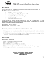
indoor temperature
indoor humidity is 41%
fan is
OFF
fan is
AUTO
cool−to
set temp
75
heat to
72
heat
or
cool
fan is
AUTO
away
mode
outdoor
temperature
80
system is cooling
9:39 am Aug 15, 2012
Wi−Fi
THIS MANUAL MUST BE LEFT WITH THE HOMEOWNER
FOR FUTURE REFERENCE
NOTICE
Read this manual before programming this thermostat.
Use this thermostat only as described in this manual.
INSTALLER’S SYSTEM SETUP
GUIDE
icomfort Wi-Fi Thermostat
Touch Screen Programmable Communicating Thermostat
CONTROLS
506920−01
09/12
Supersedes 05/12
icomfort−Enabled Units
G71MPP−03 or later XC17−02 or later
SLP98−01 or later XP17−02 or later
SL280−03 or later XP19−06 or later
EL296V−01 or later XC21−05 or later
CBX40UHV−02 or later XP21−01 or later
CBX32MV−06 or later
Shipping and Packing List
1 − icomfort Wi-Fi thermostat
4 − Mounting Screws
4 − Wall Anchors
1 − Installation Quick-Start Guide
1 − Installer’s System Setup Guide
1 − Homeowner’s Manual
1 − Warranty card

506920−01 09/12
Page 2
Table of Contents Page
Technical Description/Features 3. . . . . . . . . . . . . . . . . . . . . . . . . . . . . . . . . . . .
Installation and Setup 4. . . . . . . . . . . . . . . . . . . . . . . . . . . . . . . . . . . . . . . . . . .
System Settings screen 4. . . . . . . . . . . . . . . . . . . . . . . . . . . . . . . . . . . . . . . . . .
Change settings (dealer info, daylight savings, fan circulate) 5. . . . . . . . . . .
Table 1. System settings defaults and ranges 6. . . . . . . . . . . . . . . . . . . . . . .
Set Time and Date 7. . . . . . . . . . . . . . . . . . . . . . . . . . . . . . . . . . . . . . . . . . . . . .
Add or Remove Non−communicating equipment 9. . . . . . . . . . . . . . . . . .
Maintenance Timers 9. . . . . . . . . . . . . . . . . . . . . . . . . . . . . . . . . . . . . . . . . .
Outdoor Unit 10. . . . . . . . . . . . . . . . . . . . . . . . . . . . . . . . . . . . . . . . . . . . . . . .
Humidifier 11. . . . . . . . . . . . . . . . . . . . . . . . . . . . . . . . . . . . . . . . . . . . . . . . . .
Dehumidifier 12. . . . . . . . . . . . . . . . . . . . . . . . . . . . . . . . . . . . . . . . . . . . . . . .
Adjust a setting screen 13. . . . . . . . . . . . . . . . . . . . . . . . . . . . . . . . . . . . . . . .
Configure Humidifier 15. . . . . . . . . . . . . . . . . . . . . . . . . . . . . . . . . . . . . . . . . .
Configure Dehumidifier (Humiditrol®/Aux. Dehum. installed) 16. . . . . . . .
Configure Dehumidification (no dehumidifier installed) 17. . . . . . . . . . . . . .
Humidification and Dehumidification Modeshow they work 18. . . . . . . . . . .
Use the Test Features 19. . . . . . . . . . . . . . . . . . . . . . . . . . . . . . . . . . . . . . . . . . .
Set up Equipment Parameters 20. . . . . . . . . . . . . . . . . . . . . . . . . . . . . . . . . . . .
Use the Diagnostic Features 21. . . . . . . . . . . . . . . . . . . . . . . . . . . . . . . . . . . . .
View and Clear Alerts 22. . . . . . . . . . . . . . . . . . . . . . . . . . . . . . . . . . . . . . . . . . .
Enable Wi−Fi from User Home Screen 24. . . . . . . . . . . . . . . . . . . . . . . . . . . . . .
Register the icomfort
Wi-Fi thermostat 26. . . . . . . . . . . . . . . . . . . . . . . . . . . .
Personal Computer account registration to icomfort
Wi-Fi server 26. . . . . .
PC Welcome screen, interactive demo, Gelaskins 27. . . . . . . . . . . . . . . . . . . .
Access Installer Program from User Home Screen 28. . . . . . . . . . . . . . . . . . .
Reconfigure a System 29. . . . . . . . . . . . . . . . . . . . . . . . . . . . . . . . . . . . . . . . . . .
Stage Delay Timers & Differentials 30. . . . . . . . . . . . . . . . . . . . . . . . . . . . . . . .
Smooth Setback Recovery (SSR) 31. . . . . . . . . . . . . . . . . . . . . . . . . . . . . . . . .
Heat Pump, Dual Fuel and Balance Points 32. . . . . . . . . . . . . . . . . . . . . . . . . .
Gas Heat Control Mode 34. . . . . . . . . . . . . . . . . . . . . . . . . . . . . . . . . . . . . . . . .
Table 2. Variable Capacity Furnace Operation 35. . . . . . . . . . . . . . . . . . . . . . .
Table 3. Adjustable Parameters (Installer) 37. . . . . . . . . . . . . . . . . . . . . . . . . . .
Table 4. Adjustable Parameters (User) 43. . . . . . . . . . . . . . . . . . . . . . . . . . . . .
Table 5. Alert Codes and Troubleshooting 45. . . . . . . . . . . . . . . . . . . . . . . . . . .
Homeowner Service Codes 54. . . . . . . . . . . . . . . . . . . . . . . . . . . . . . .
Table 6. Troubleshooting Tips 55. . . . . . . . . . . . . . . . . . . . . . . . . . . . . . . . . . . . .
Wiring Diagrams 59. . . . . . . . . . . . . . . . . . . . . . . . . . . . . . . . . . . . . . . . . . . . . . . .
Thermostat wire termination in communicating system 63. . . . . . . . . . . . . . . .
Table 7. Replacement Controls 72. . . . . . . . . . . . . . . . . . . . . . . . . . . . . . . . . . . .
Setting up typical icomfort systems
Indoor Unit Outdoor Unit page
icomfort−enabled
furnace
icomfort enabled AC 65
non−communicating AC 66
icomfort−enabled
furnace (dual fuel)
icomfort enabled HP 67
non−communicating HP not supported
icomfort−enabled
air handler
icomfort enabled AC 68
non−communicating AC 69
icomfort−enabled
air handler
icomfort enabled HP 70
non−communicating HP 71
CAUTION
This is a 24VAC Class 2 thermostat. Do not install on voltages higher than
30VAC.
Do not switch system to cool if the outdoor temperature is below 45°F
(7°C). This can damage the cooling system.
WARNING
Electric shock hazard.
Always turn off power at the main power source by switching the circuit
breaker to the OFF position before installing or removing this thermostat.
All wiring must conform to local and national building and electrical
codes and ordinances.

icomfort Wi-Fi 7−Day Programmable Communicating Thermostat
Page 3
icomfort Wi-Fi Thermostat − Technical Description and Features
The 24VAC icomfort Wi-Fi thermostat (figure 1) is an electronic communi-
cating, color display touchscreen, 7−day programmable thermostat. It stores
system parameters and settings in nonvolatile memory (i.e., it retains data
when electrical power fails or is turned off). It is designed for 4−wire connec-
tion to other communication devices as listed in figure 1.
The icomfort Wi-Fi thermostat can connect to online services via the inter-
net through the homeowner’s Wi−Fi access point. After online registration is
completed, the system may then be accessed by the homeowner from any-
where using a remote internet connection via computer or personal commu-
nicating device.
Thermostat
connections
RSBus
Minimum wire
size is 18 gauge
icomfort−enabled Furnace Control
icomfort−enabled Air Handler Control
icomfort−enabled Outdoor Unit Control
External Sensors − outdoor temperature, discharge air
Humidify Control
Dehumidify Control
R i+ i− C
Maximum total length of all
connections on the RSBus is
limited to 1500 ft. (450 m).
Max. length between compo-
nents is 300 ft. (90 m).
Note: icomfort
Wi-Fi thermo-
stat does not
require
shielded cable
wiring.
RED
GREEN
WHITE
YELLOW
Figure 1. icomfort by Lennox system
BEST PRACTICES! Keep all communication wiring as far away from house
electrical wiring and large electrical appliances as possible (15’ [5m] recom-
mended).
The thermostat also:
supports three languages (English, French, Spanish),
supports air conditioning units or heat pump units with up to four stages
of heat / two stages of compressor operation (2 stages of heat pump
heating, 2 stages of auxiliary back−up heating, 2 stages of emergency
heating),
supports Indoor Air Quality with time-based notification of consum-
ables including media filters, UVC bulbs, humidifier pads, and Pure-
Air system catalyst service / replacement,
supports variable−capacity / multi−stage heat/cool, universal compati-
bility (gas/electric/heat pump/ac), and is dual fuel capable (icomfort−
enabled HP only) with two balance points.
Important
Connections to non−communicating outdoor units and accessories are de-
scribed in the Quick−Start Installation guide. (Wiring diagrams are also
shown beginning on Page 59 of this manual.)
Supports
Humidification Measurement and Control,
Dew Point Adjustment Control
Dehumidification Measurement and Control
Humiditrol
®
Enhanced Dehumidification Accessory (EDA)
Multi-Stage HVAC Systems
Equipment Maintenance Reminders
Autochangeover Mode −− Permits control of heating, cooling, humidifi-
cation, and dehumidification without user involvement.
Outdoor Temperature Sensor (option)
Communicating outdoor units contain a built−in outdoor temperature sensor.

506920−01 09/12
Page 4
Installation and Setup
IMPORTANT! Make sure the router is capable of, and set to operate in
wireless network b" mode. Check router utility program or contact
service provider for help. When determining the location for the Wi−Fi ther-
mostat, be sure it is in an area near enough to the homeowner’s Wi−Fi router
to ensure good communications signal between the thermostat and the rout-
er. (Hint: use a smart phone with Wi−Fi to find and determine signal
strength.)
Refer to the Quick Start Guide for information about installing the thermostat
on a wall and for wiring diagrams for field wiring the thermostat to the system
using one of a number of possible configurations. (Wiring diagrams are also
shown beginning on Page 59 of this manual.)
NOTE − If electric heat strips are used with an icomfortt−enabled air handler,
the strips MUST be configured on the air handler control (AHC) board before
beginning the discovery" sequence below.
After all wiring connections are made, apply power to the system. 24VAC will
power up the thermostat.
After power is applied to the thermostat for the
first time, the processor checks the system for
installed communicating devices, the So Sim-
ple. So Smart. So Comfortable" screen dis-
plays; followed by Use this thermostat?"
screen. Touch press here to continue. During
the setup process, alerts may pop open to provi-
de the installer with information that affects the
setup. Correct the cause of any such alerts
prior to continuing setup.
System settings (figure 2) appear first. As you use the up/down arrows to
scroll through the settings, the right hand side will show the current value.
For example, current value: 9:39 am Aug 15, 2012 shows the current date
for Time and Date.
system settings
To adjust a setting, highlight it, then
press edit
9:39 am Aug 15, 2012
next
back
current value:
Time and Date
Daylight Saving Time
Circulate Fan ON Time
System Name
Dealer Number
Dealer Name
Dealer Address
Dealer Phone
Dealer Email
Dealer Website
9:39 am Aug 15, 2012
edit
Figure 2. System settings" screen
(Thermostat 1)
Use this Thermostat?
press here

icomfort Wi-Fi 7−Day Programmable Communicating Thermostat
Page 5
Circulate Fan ON Time Range
is 15 to 50 %
Default is 35, inc: 1
cancelsave
set−to
45%
up/down
arrows
radio
buttons
Not Installed 1 Stage A/C Unit
2 Stage A/C Unit 1 Stage HP Unit
2 Stage HP Unit
Select one
Outdoor Unit Type
cancelsave
Dealer Name
keyboard
tool
Figure 3. Settings change tools
Change settings
If you want to change a setting, use one of the Settings change tools shown
in figure 3. (Also, see Set time and date on Page 7.) After changes have
been made, use save to store the changed data or cancel to exit the screen
and return to the list of settings.
Dealer Number
Use the arrows to scroll to the Dealer Number setting. Press edit and use the
typewriter tool (shown in figure 3) to enter your dealer number. Press save to
store the identification.
system settings
To adjust a setting, highlight it, then
press edit
9:39 am Aug 15, 2012
current value:
Time and Date
Daylight Saving Time
Circulate Fan ON Time
System Name
Dealer Number
Dealer Name
Dealer Address
Dealer Phone
Dealer Email
Dealer Website
edit
next
back
Figure 4. Entering Dealer Number"

506920−01 09/12
Page 6
Circulate fan ON time setting
NOTE − If the circulate fan mode is on, a timer is set to measure all the time
that the fan is blowing, regardless if it is running to deliver heating or cooling
or just for circulation.
Circulate" is enabled on the user’s home screen or system settings page.
It keeps air circulating from 15% to 50% percent of time. The following set-
tings approximate how long the fan will run at these typical settings:
15% (9 minutes fan run time per hour)
25% (15 minutes fan run time per hour)
35% (21 minutes fan run time per hour)
45% (27 minutes fan run time per hour).
Table 1 shows the range/condition and defaults for the system settings and
indicates the tools used to make changes.
Table 1. System setting defaults and range
system
setting
range/
condition
default use
Time and Date see Page 7
Daylight Saving
Time
Enabled/Disabled Enabled
Circulate Fan
ON Time
15 to 50% (in 1%
increments)
35%
System Name
(alpha−numeric
characters)
use keyboard
tool to change
Dealer Number
(alpha−numeric
characters)
****
use keyboard
tool to change
Dealer Name
Lennox
1−800−9−LENNOX
www.lennox.com
Dealer Address
Dealer Phone
Dealer Email
Dealer Website

icomfort Wi-Fi 7−Day Programmable Communicating Thermostat
Page 7
Set time and date
Use the arrows to select Time and Date; press edit (see figure 5) to proceed
to the Set current time and date" screen (figure 6).
system settings
To adjust a setting, highlight it, then
press Edit
9:39 am Aug 15, 2012
edit
nextback
current value:
9:39 am Aug 15, 2012
Time and Date
Daylight Saving Time
Circulate Fan ON Time
System Name
Dealer Number
Dealer Name
Dealer Address
Dealer Phone
Dealer Email
Dealer Website
Figure 5. View/edit time and date
When Time and Date" screen (figure 6) appears, enter the correct date as
follows:
Use the left and right arrows to change the month and year.
Touch a day of the month to select it.
Press on the hour or minute; up down arrows appear to allow change.
Touch the am/pm field to toggle it between am and pm.
When the correct date and time is set, press save to save settings and
return to previous settings screen.
Touch next to continue to next screen.
SMTWTFS
January 2012
system settings
1234567
8 9 10 11 12 13 14
15 16 17 18 19 20 21
22 23 24 25 26 27 28
29 30 31
save
09 : 39 am
9:39 am Aug 15, 2012
Figure 6. Set current time and date

506920−01 09/12
Page 8
Use about" screen & access Add or Remove Non−communicating equipment" screen
The about" screen shows details of discovered installed equipment.
From the system devices" screen, use arrow buttons to scroll to a device; then press the about button. Use the up/down arrows to scroll through and view
additional information about the selected device. When finished viewing, press the back button.
Press next to advance to the Add or Remove Non−communicating equipment?" screen.
device feature list
Furnace
device description
Equipment Type Name
Furnace
back
Language Support
Equipment Type Name
Unit Model Number
Unit Serial Number
Unit Nominal Capacity
Number of Heating Stages
Heating Capacity by Stage
Indoor Blower CFM Range
Control Software Revision
Control Model Number
(returns to
system
devices
screen)
about
back next
9:39 am Aug 15, 2012
press ’about’ for
more information on
a highlighted device
System
Heat Pump
Furnace
Thermostat
system devices
system devices
yes
System
Heat Pump
Furnace
Thermostat
If no, press Next
Step.
Add or Remove
Non−communi-
cating equip-
ment?
back next
Figure 7. Using the about" screen and accessing Add or Remove Non−communicating equipment" screen

icomfort Wi-Fi 7−Day Programmable Communicating Thermostat
Page 9
Add or Remove Non−communicating equipment
Figure 7 (previous page) shows how to access the Add or Remove Non−
communicating equipment" screen.
Adding Non−Communicating Outdoor unitSee figure 8 for details
for adding/removing an outdoor unit.
Adding HumidifierThe procedures in figure 9 describe adding a non−
communicating humidifier which will be controlled by the icomfort Wi-Fi
thermostat through the H" or HUM" terminals on the furnace or air handler.
Adding DehumidifierThe procedures in figure 10 describe adding a
non−communicating dehumidifier controlled by the icomfort Wi-Fi thermo-
stat through the DH" output on the furnace or air handler.
NOTICE
For details about how the humidification and dehumidification
modes operate and how to configure those modes, see additional in-
formation beginning on Page 18.
HUMIDITY CONTROL TIPS
The standard humidification mode is Basic" (humidifier is energized
during a call for heat, if there is a humidification demand).
Sensed outdoor temperature, required for some features, is provided
from one of the following sources:
A downloaded via Wi−Fi when available (primary source),
B sensor furnished with icomfort−enabled outdoor units,
C separate outdoor sensor connected to the furnace or air handler
outdoor sensor" connections.
NOTE − If no source for outdoor temperature is present, Basic and
Precision Dew Point Control" modes are not available.
If you do not have the ability to select or adjust the Humidity RH set-
point on the Indoor Humidity" button, the control is set for Display
Only." In the installer program, go the equipment button and select
System" and press the edit button. Select Humidification Control
Mode" and press edit. Choose Basic," Precision," Basic Dew Point
Control" or Precision Dew Point Control" and press save.
Adding non−communicating accessoriesAdding maintenance
timer reminders to accessories is a simple process of installing" the device,
which effectively tells the thermostat to activate access to its service timers.
Timers are available for two (2) filters, Humidifier pad, UV bulb maintenance
and the PureAir Air Purification system.

506920−01 09/12
Page 10
Add Non−Communicating Outdoor unit
System Devices
Add or Remove
Non−communicating
equipment?
yes
nextback
1
non−communicating device list
Not Installed
current value:
back
edit
Not Installed 1 Stage A/C Unit
2 Stage A/C Unit 1 Stage HP Unit
2 Stage HP Unit
Select one
Outdoor Unit Type
cancelsave
To add (or remove) an outdoor unit that is not icomfort−enabled, you must be at
the Add or Remove Non−communicating equipment?" screen.
1. Press the yes button on this screen (see 1).
2. In the non−communicating device list" screen, use the arrows (2a) to
highlight Outdoor Unit Type and press edit (2b).
3. Touch one of the radio buttons (3a) to select a 1−or 2−Stage AC Unit or a
1−or 2−Stage HP Unit; press save (3b).
4. Use arrows (4a) to highlight any red colored text in the device list (e.g.
select Outdoor Unit Capacity; text turns white). Press edit (4b).
5. Use arrows (5a) to make changes; press save (5b). Change other red
settings (if present) using a similar process.
NOTE − If the defaults are correct, you do not have to make any changes, but you
must press save (5b). When all red text is gone, the back button will appear; press
it to return to the Add or Remove Non−communicating equipment?" screen (1).
3b
3a
to add/remove/adjust a device,
select it, then press edit
current value:
non−communicating device list
edit
to add/remove/adjust a device,
select it, then press edit
back
please view and save all
red settings
9:39 am Aug 15, 2012
2 Stage AC Unit
4a
4b
2a
2b
Outdoor Unit Type
Outdoor Unit Capacity
Outdoor Unit 1st Stage Capacity
Humidifier
Dehumidifier
Outdoor Unit Type
Humidifier
Dehumidifier
System
Furnace
Outdoor Unit Capacity
Range is 18 to 60
Default is 36, inc:1
cancelsave
set−to
36
5b
5a
Figure 8. Add non−communicating deviceOUTDOOR UNIT

icomfort Wi-Fi 7−Day Programmable Communicating Thermostat
Page 11
Add (or Remove) Humidifier (skip if no humidifier is being used)
NOTE − Adding humidity regulating non−communicating devices may be a 2−step procedure:
1st, the device must be installed (this page; after the humidifier is installed, the operation
mode defaults to Basic").
2nd, (if you want another mode, i.e. Precision, Basic Dew Point, or Precision Dew Point,
the device requires further configuration (see Page 15).
To add (or remove) a humidifier,:
1. Press the yes button on this screen (see 1).
2. In the non−communicating device list" screen, use the arrows (2a) to highlight
Humidifier (note the current value, Not Installed) and press edit (2b).
3. Touch one of the radio buttons (3a) to select the type of humidifier (or select Not
Installed, if removing humidifier); press save (3b).
4. The previous screen returns, but the current value now shows your selection (4a).
Press the back (4b) button.
5. The Add or Remove..." screen reappears with your addition shown in the system
devices list (5a). At this point, you may add more equipment (press yes) or if
finished, press the next (5b) button to advance to the Adjust a setting..." screen
(see page 15).
6. (If you want other than the default Basic" mode of operation) Configure the
humidifier as described on Page 15.
nextback
Before adding a humidifier, be sure that:
the humidifier is wired to the furnace or air handler control as shown on the Optional
Accessories wiring diagram (see Page 61),
the entire system is wired, powered up, and the thermostat has detected the system’s
installed communicating devices, and you are at the Add or Remove Non−communi-
cating equipment?" screen (see figure 7, Page 8).
system devices
System
Heat Pump
Furnace
Thermostat
yes
edit
to add/remove/adjust a device,
select it, then press edit
Not Installed
current value:
non−communicating device list
2a
Humidifier
Dehumidifier
Electronic Air Cleaner
1
Add or Remove Non−
communicating
equipment?
Select one
Humidifier
cancelsave
3b
(available with furnace equipped systems only)
2b
Not Installed Bypass (24VAC) Humidifier
Power (120VAC) Humidifier Bypass and Power Humidifier
edit
to add/remove/adjust a device,
select it, then press edit
Bypass (24VAC) Humidifier
current value:
non−communicating device list
Humidifier
Dehumidifier
Electronic Air Cleaner
back
5a
system devices
9:39 am Aug 15, 2012
nextback
yes
Add or Remove Non−
communicating
equipment?
4a
4b
System
Heat Pump
Furnace
Thermostat
Bypass (24VAC) Humidifier
5b
3a
Figure 9. Add or remove non−communicating deviceHUMIDIFIER

506920−01 09/12
Page 12
Add (or Remove) Humiditrol
®
or Auxiliary Dehumidifier (skip if no dehumidifying device is being used)
Before adding a dehumidifier, be sure that:
the dehumidifier is wired to the furnace or air handler control as shown on the Option-
al Accessories wiring diagram (see Page 61),
the entire system is wired, powered up, and the thermostat has detected the sys-
tem’s installed communicating devices, and you are at the Add or Remove Non−
communicating equipment?" screen (see figure 7, Page 8).
Add or Remove
Non−communicating
equipment?
If ’no’, press Next Step
yes
nextback
edit
to add/remove/adjust a device,
select it, then press edit
Not Installed
current value:
non−communicating device list
NOTE − Adding humidity regulating non−communicating devices may be a 2−step procedure:
1st, the device must be installed (this page; after the dehumidifier is installed, the opera-
tion mode defaults to Basic").
2nd, set Humiditrol
®
comfort adjust overcooling and the min/max dehumidification set-
points if desired (see Page 16).
To add (or remove) a dehumidifier, you must be at the Add or Remove Non−communicating
equipment?" screen.
1. Press the yes button on this screen (see 1).
2. In the non−communicating device list" screen, use the arrows (2a) to highlight
Dehumidifier and press edit (2b). Note the current value (e.g. Not Installed).
3. Touch one of the radio buttons (3a) to select the type of dehumidifier (or select Not
Installed, if removing dehumidifier); press save (3b).
4. When you scroll to the Dehumidifier device (4a), (Note the current value, e.g.
Humiditrol.) Click back (4b) to return to the Add or Remove..." screen (1).
5. The Add or Remove..." screen reappears with your addition shown in the system
devices list (5a). At this point, you may add more equipment (press yes) or if
finished, press the next button (5b) to advance to the Adjust a setting..." screen
(see Page 13).
Humiditrol
®
NoteBy default, the Humiditrol Comfort Adjust (HCA) is configured for maxi-
mum overcooling and minimum dehumidification setpoint of 40% RH. If these settings are
satisfactory, no further configuration is necessary. If another setting is needed, change HCA
and setpoint as described on Page 16.
1
2b
Not Installed Humiditrol
Auxiliary Dehumidifier
Select one
Dehumidifier
cancelsave
3b
3a
system devices
System
Furnace
Humidifier
Dehumidifier
Electronic Air Cleaner
edit
to add/remove/adjust a device,
select it, then press edit
Humiditrol
current value:
non−communicating device list
Humidifier
Dehumidifier
Electronic Air Cleaner
back
5a
system devices
nextback
yes
Add or Remove Non−
communicating
equipment?
System
Heat Pump
Furnace
Thermostat
Humiditrol
4a
4b
2a
5b
Figure 10. Add or remove non−communicating deviceDEHUMIDIFIER

icomfort Wi-Fi 7−Day Programmable Communicating Thermostat
Page 13
Adjust a setting screen (communicating devices)
Use arrows to select a device from the system devices" list; then use the about button to view information (shown on Page 8) about communicating
devices (information about other devices is not available).
Use resetAll button to un−install all non−communicating devices that were added through Add or Remove..." screen and to reset any device settings made
through this Adjust a setting..." screen to the factory defaults. (While editing a communicating device, the reset button is limited to only the selected device.
You are asked to confirm (shown in figure 11) before resetting all.
Use this screen to access communicating devices’ settings (pressing buttons numbered from 1 to 6 in figure 11 for an example of changing heating airflow;
more examples are shown on the next page). Use back to return to the previous screen or next to go on. A complete list of parameters, their defaults and
setting ranges, begins on page 37.
Low Heating Airflow
Range is 325 to 450
Default is 400, inc:25
set−to
325
cancelsave
system devices
Furnace
edit
about
next
resetAll
back
To adjust a setting,
highlight it, then press
Edit
System
Furnace
Thermostat
2 Stage HP Unit
Power (120VAC) Humidifier
Humiditrol
system devices
current value:
reset
back
Equipment Name
Heating Airflow Control Type
Low Heating Airflow
High Heating Airflow
High Cooling Airflow
Airflow Profile − Cooling
High HP Airflow
Continuous Indoor Blower Airflow
Low Heating Airflow
325
edit
1
2
3
4
5
6
resetting a device to its factory default
(resetting ALL devices to their factory default)
settings will cause the system to restart the
setup process.
To continue, press CONFIRM or press CANCEL
confirm
(if resetAll
is pressed)
cancel
Figure 11. Adjust communicating device screens

506920−01 09/12
Page 14
Use the up/down arrows to scroll through the device’s settings. The current setting will be displayed on the right−hand side of the screen (figure 12). For
example, current value: disabled. Press edit if you want to modify that setting, or press back to return to the previous screen.
Available settings for the devices depend on the installed components. Shown below is an example of enabling and changing the balance point control from
default (Disabled) to Enabled. After selecting Enabled, press save to save the changes and return to the previous screen.
The returning screen may appear with the message in red please view and save all red settings." In the example in figure 13, note that two additional items are
listed in red. Use the arrows to scroll and highlight each item appearing in red. Press edit, make any desired changes, and press save.
When all affected settings have been edited/saved, the red message disappears. Press back to return to the To adjust a setting..." screen.
If no more adjustments are necessary, press next to advance to the select tests to run" screen (see Page 19).
System
current value
edit
reset
back
Balance Point Control
Disabled
Staged Delay Timers
2nd Stage Delay
3rd Stage Delay
Balance Point Control
Humiditrol Comfort Adjust
Humidification Control Mode
Min Dehumidification Setpoint
OK/Humid BoundaryDisabled Enabled
Select one
Balance Point Control
cancelsave
Figure 12. Accessing device to modify
Staged Delay Timers
2nd Stage Delay
3rd Stage Delay
Lock In 2nd stage HP by Outdoor Temp
Balance Point Control
High Balance Point
Low Balance Point
Humiditrol Comfort Adjust
Humidification Control Mode
Min Dehumidification Setpoint
System
current value
edit
reset
back
Balance Point Control
Enabled
please view and save all
red settings
High Balance Point
Range is −17 to 75
Default is 0, inc:1
cancelsave
set−to
50
Figure 13. Modify device settings
G71MPP or SLP98 Furnace Note:
If your icomfort Wi-Fi thermostat is being used with a G71MPP or SLP98 furnace and is set to variable−capacity mode of operation (the icomfort default
with these units), the thermostat’s settings for stage timers are ignored (even if shown enabled in the thermostat). The stage timer will be used on the cooling
side. The furnace software sets and controls the firing rates. The only other controlling factor is the stage temperature differentials. In Load−Tracking Variable
Capacity (default for these furnaces), both stage timers and temperature differentials are ignored.

icomfort Wi-Fi 7−Day Programmable Communicating Thermostat
Page 15
Adjust a setting... Configure Humidifier (skip if no humidifier is being used or if humidifier is being used and default
Basic" humidification mode is desired)
System Devices
edit
about
To adjust a setting, highlight it,
then press Edit
System
resetAll
next
back
1a
1b
edit
reset
Humidification Control Mode
current value:
back
Basic
Pre−adjustment REQUIREMENTS:
1st, the device has been installed (see Page 11).
2nd, you pressed next at the Add or Remove..." screen (see Page 11).
Configure the device as follows:
1. In the system devices" list, use the arrows (1a) to highlight System. Press edit (1b).
2. In the System" list, use the arrows (2a) to highlight Humidification Control Mode.
The current value defaults to Basic mode. Press edit (2b).
3. Touch one of the radio buttons (3a) to select the mode of humidification control;
press save (3b). (After saving, check that the current value now shows the new
selection).
4. Use arrows (4a) to highlight any red colored text in the list (e.g. select Max Humidifi-
cation Setpoint). Press edit (4b).
5. Use arrows (5a) to make changes; press save (5b). Repeat for other red settings.
You will not be able to advance to the next step until all red settings have been
removed..
6. Press the back button to return to Adjust a setting..." screen.
NOTE − If the defaults for the settings shown in red, you are not required to make any changes,
but you must go into the edit tool, and press save (5b). When all red text is gone, the back button
will appear; press it to return to the Adjust a setting..." screen.
Display Only Basic
Precision Basic Dew Point Control
Precision Dew Point
Select one
Humidification Control Mode
cancelsave 3b
3a
edit
reset
back
Max Humidification Setpoint
current value:
45
9:39 am Aug 15, 2012
please view and save all
red settings
2a
2b
System
Air Conditioner
Furnace
Thermostat
Power (120VAC) Humidifier
Max Humidification Setpoint
Range is 15 to 45
Default is 45, inc:1
cancelsave
set−to
45
5b
5a
(returns to
adjust a
setting
screen)
4b
4a
System
1st Stage Differential
2nd Stage Differential
Staged Delay Timers
2nd Stage Delay
Dehumidification Control Mode
Humidification Control Mode
Max Humidification Setpoint
OK/Humid Boundary
Outdoor Temperature Reading
System
2nd Stage Differential
Staged Delay Timers
2nd Stage Delay
Dehumidification Control Mode
Humidification Control Mode
Figure 14. Adjust a non−communicating device settingHUMIDIFIER

506920−01 09/12
Page 16
Adjust a setting... Configure Humiditrol
®
or Auxiliary Dehumidifier
edit
about
To adjust a setting,
highlight it,
then press Edit
System
reinstall
edit
reset
Dehumidification Control Mode
current value:
back
Midpoint Overcooling
Pre−adjustment REQUIREMENTS:
1st, the device has been installed (see Page 12).
2nd, from the Add or Remove Non−communicating equipment?", press next.
3rd, in the Adjust a setting..." screen, configure the device as follows:
1. In the system devices" list, use the arrows (1a) to highlight System. Press
edit (1b).
2. Humiditrol
®
onlyIn the System" list, use the arrows (2a) to highlight
Humiditrol Comfort Adjust. The current value defaults to Maximum Over-
cooling. Press edit (2b).
3. Humiditrol
®
onlyTouch one of the radio buttons (3a) to select the over-
cooling level; press save (3b). (After saving, check that the current value
now shows the new selection).
4. Use arrows (4a) to highlight Min Dehumidification Setpoint; press edit
(4b). Note the current value (e.g. 45).
5. Use arrows (5a) to make changes; press save (5b). (After saving, check
that the current value now shows the new selection).
6. Press the back button to return to Adjust a setting..." screen.
1a
1b
2a
system devices
System
Air Conditioner
Furnace
Thermostat
Humiditrol
Maximum Overcooling Midpoint Overcooling
Minimum Overcooling
Select one
Humiditrol Comfort Adjust
cancelsave
3b
3a
System
3rd Stage Delay
4th Stage Delay
Lock In 2nd Stage HP by Outdoor Temp
Balance Point Control
Humiditrol Comfort Adjust
Min Dehumidification Setpoint
edit
reset
back
Dehumidification Control Mode
current value:
45
9:39 am Aug 15, 2012
4a 4b
Humiditrol Comfort Adjust settings are
only available on units equipped with
a Humiditrol
®
dehumidification device.
See Page 18 for description of Min/
Mid/Max overcooling.
resetAll
2b
6
Min Dehumidification Setpoint
Range is 40 to 60
Default is 45, inc:1
cancelsave
set−to
42
5a
5b
(returns to
adjust a
setting
screen)
System
Staged Delay TImers
2nd Stage Delay
3rd Stage Delay
4th Stage Delay
Lock In 2nd Stage HP by Outdoor Temp
Balance Point Control
Humiditrol Comfort Adjust
Min Dehumidification Setpoint
OD/Humid Boundary
Outdoor Temperature Reading Calibr
Figure 15. Adjust a non−communicating device settingDEHUMIDIFIER

icomfort Wi-Fi 7−Day Programmable Communicating Thermostat
Page 17
Adjust a setting... Configure Dehumidification (no dehumidifying device installed)
(skip if default Basic" dehumidification mode is desired)
edit
about
To adjust a setting, highlight it,
then press Edit
reinstall
next
back
edit
reset
Dehumidification Control Mode
current value:
back
Display Only
Display Only Basic
Precision
Select one
Dehumidification Control Mode
cancelsave
3b
3a
edit
reset
back
Dehumidification Control Mode
current value:
Precision
9:39 am Aug 15, 2012
please view and save all
red settings
Pre−adjustment REQUIREMENTS:
1st, NO physical dehumidification device has been installed.
2nd, configure the thermostat for dehumidification as follows:
1. In the system devices" list, use the arrows (1a) to highlight System.
Press edit (1b).
2. In the System" list, use the arrows (2a) to highlight Dehumidification
Control Mode. The current value defaults to Display Only. Press edit
(2b).
3. Touch one of the radio buttons (3a) to select the mode of dehumidification
control; press save (3b).
4. Use arrows (4a) to highlight any red colored text in the list (e.g. select Min
Dehumidification Setpoint). Press edit (4b).
5. Use arrows (5a) to make changes; press save (5b). Change other red
settings (e.g. Auto Changeover − Humidif. Deadband) using a similar
process.
6. Press the back button to return to Adjust a setting..." screen.
NOTE − If the defaults are correct, you do not have to make any changes, but you
must press save (5b). When all red text is gone, the back button will appear; press it
to return to the Add or Remove Non−communicating equipment?" screen.
1a
1b
2a
2b
4a
4b
System
Staged Delay Timers
Balance Point Control
Dehumidification Control Mode
Humidification Control Mode
Auto Changeover − Humidif. Deadband
Max Humidification Setpoint
Min Dehumidification Setpoint
OK/Humid Boundary
Outdoor Temperature Reading
System Devices
System
Furnace
Thermostat
2 Stage AC Unit
Power (120VAC) Humidifier
System
2nd Stage Differential
Staged Delay Timers
2nd Stage Delay
Dehumidification Control Mode
Humidification Control Mode
OK/Humid Boundary
Outdoor Temperature Reading
System
Min Dehumidification Setpoint
Range is 40 to 60
Default is 45, inc:1
cancelsave
set−to
45
5a
5b
6
Figure 16. Adjust dehumidification when not using Humiditrol or an auxiliary dehumidifier

506920−01 09/12
Page 18
Humidification and Dehumidification Modeshow they work
HUMIDIFICATION modes
BASIC & PRECISIONThese modes allow user control of RH between 15
and 45%. These conditions must be met for either mode to operate:
humidification mode has been enabled, and
the unit is in HEAT mode, and
humidification demand exists (24V present at H), and
BASIC mode also requires presence of heating demand [Y for HP
heat, or W for gas heat (W may be energized with G de−energized)].
DEW POINT(Available only if Wi−Fi is operational or outdoor sensor is at-
tached)
Basic Dew Point ControlBasic Dew Point Control adjustment mode will
change the humidification setpoint based on the outdoor temperature and a
user−defined dew point adjustment setting.
Precision Dew Point ControlPrecision Dew Point Control adjustment
mode will operate when these conditions are met:
humidification mode has been enabled, and
the unit is in HEAT mode, and
humidification demand exists (24V present at H).
DEHUMIDIFICATION modes
NOTE − Basic and Precision dehumidification modes are functions of the
HVAC system with NO external dehumidification devices installed. Humidi-
trol and Auxiliary Dehumidifiers do not use these modes.
In BASIC mode, dehumidification occurs if these conditions are met and sig-
nals are present at specific terminals:
dehumidification has been enabled on installer settings, and
the unit is in COOL mode, and
dehumidification demand exists (RH above setpoint), and
cooling demand exists (Y1 energized).
In PRECISION mode, dehumidification occurs if all BASIC conditions are
true, except cooling demand may or may not be present. Also note that:
Maximum overcool from cooling setpoint is 2ºF.
Deadband temperature is limited to a minimum of 5ºF (instead of 3ºF
in BASIC or DISPLAY ONLY mode) because of 2ºF overcooling.
Humiditrol
®
or Auxiliary Dehumidifier mode requires:
NOTE − Systems using icomfortt and a dehumidifier − Dehum" jumper on
furnace/air handler control does not need to be cut when using with a icom-
fort Wi-Fit thermostat.
Wi−Fi is operational or outdoor sensor is installed and set up
dehumidification has been enabled on installer settings, and
the unit is in COOL mode, (or if in AUTO, at least one thermostat cool-
ing call made prior to the dehumidification demand), and
a dehumidification demand exists (RH above setpoint), and
outdoor temp. below 95°F; indoor temp. above 65°F, and
for HUMIDITROL, adjust Humiditrol
®
comfort parameters as follows:
MAX adj. − Indoor temp > 2°F above heating setpoint
MID adj. − Indoor temp >
HEAT Setpoint+COOL Setpoint
2
MIN adj. − Indoor temp > 2°F below cooling setpoint
Auxiliary Dehumidifier (stand alone dehumidifier)
When this option is selected, dehumidification will be allowed under the fol-
lowing conditions, provided there is NO call for humidification:
In the absence of heating or cooling calls, or
Simultaneous with blower only calls.
If the blower is required to operate while the auxiliary dehumidifier is running,
a separate wire must be installed from the auxiliary dehumidifier to the indoor
unit’s G thermostat input that will energize G when the auxiliary dehumidifier
is running (see wiring diagram on Page 61).
Auxiliary dehumidification is controlled by the thermostat dehumidification
demand.
NOTE − Refer to HCWH Dehumidifier Installation Instructions for installation
recommendations.

icomfort Wi-Fi 7−Day Programmable Communicating Thermostat
Page 19
Use the Tests / Diagnostics features
NOTE − Test mode lasts for 30 minutes (with the temperature updating every
30 seconds) except for the defrost test, which lasts 30 seconds. Tests fea-
ture provides the technician time to manually verify the equipment operation.
The tests feature is available after setup has been completed once. After
you press next in the final setup screen, the select tests to run" screen (fig-
ure 18) will appear. (If you want you may skip tests; press skip tests.)
If you re−select the tests button from the full option screen (figure 17), a mes-
sage to press Start button below to begin system testing" appears. Press
start. The resulting screen will be identical to figure 18.
9:39 am Aug 15, 2012
EXIT
equipment diagnostics
tests alertssetup
press start button below to begin system testing
back
start
Figure 17. Start testing screen
To run all of the tests, press select all. All boxes in the list of tests will be
checked. Or, touch box(es) next to test(s) to run certain tests.
After the tests have been started, the screen will describe which test is run-
ning and shows a diagnostic summary of each test (see figure 19). After re-
viewing the results and concluding that no further tests are needed, press
next to proceed to next test. The technician must verify that the test proce-
dure is producing the desired result at the equipment.
9:39 am Aug 15, 2012
start
skip tests
deselect all
select all
select tests to run
Blower
HP Heat − 1st Stage
HP Heat − 2nd Stage
Cooling − 1st Stage
Cooling − 2nd Stage
Dehumidification
Gas Heat − Minimum Rate
Gas Heat − Maximum Rate
Humidification
Figure 18. Select tests to run screen
9:39 am Aug 15, 2012
Heating Rate
Blower CFM Demand
Blower Off Delay
Blower On Delay
Indoor Blower RPM
Indoor Blower Power
Flame Current
Flame Sense
Outdoor Temperature
current test: Blower
Check Blower Operation
equipment
diagnosticstests
alertssetup
%
1400CFM
Off
Off
0
0.0000%
0.000mA
No Flame
63ºF
nextcancel
Figure 19. Typical tests results screens

506920−01 09/12
Page 20
After pressing next after the final test, the Testing finished" screen will ap-
pear (figure 20). At this point, use the EXIT button (if you have completed the
required setup), or use diagnostics button (to analyze the system), or use
equipment button (if you wish to make any changes to device details).
9:39 am Aug 15, 2012
EXIT
equipment diagnosticstests alertssetup
The Testing Process is finished
press ’tests’ button to run more tests
press ’EXIT’ button to start normal operation
Figure 20. Testing finished screen
Equipment, Alerts, Diagnostics
Press equipment if you need to set up equipment parameters and edit de-
tails of devices in the system (see Page 20).
Press alerts if you need to run to see any alerts that may present or to view
alerts that have been cleared (see Page 22).
Press diagnostics if you need to run to analyze the system (see Page 21).
Set up Equipment parameters
Press equipment to set up equipment parameters and edit details of de-
vices in the system without having to re−run the setup program. When the
press start..." screen (figure 21A) appears, press start. The Equipment pa-
rameters" screen (figure 21B) will open. You may view information about or
modify communicating devices as described earlier in the setup pages, be-
ginning on page 14. Use the arrows to select a device and press edit.
Use the arrows to highlight a setting and then press edit (figure 22A). In the
example, the low heating airflow is changed from the default (400) to 325 (fig-
ure 22B). After changing, press save. (note the current value has changed;
figure 22C). Some changes may affect other settings and, if so, those af-
fected will appear in red and require changing/saving to clear the red set-
tings.
equipment diagnosticstests alertssetup
press start button below to edit details of devices in the system
start
back
EXIT
9:39 am Aug 15, 2012
system devices
Furnace
To adjust a setting,
highlight it, then
press Edit
equipmenttestssetup
edit
about
next
resetAll
System
Heat Pump
Furnace
Thermostat
Humiditrol
Figure 21. Equipment parameters screen
/