h. Ifgasolineisspilled,wipeitofftheengineand
equipment,movemachinetoanotherarea.Wait5
minutesbeforestartingtheengine.
i. Neverstorethemachineorfuelcontainerinside
wherethereisanopenflame,sparkorpilotlight
asonawaterheater,spaceheater,furnace,
clothesdryerorothergasappliances.
j. Allowmachinetocool5minutesbeforestoring.
Operation
1. Before starting this machine, review the "Safety
Instructions". Failure to follow these rules may result in
serious injuryto the operator or bystanders.
2. Never leave this machine unattended with the engine
running.
3. Do not operate machine while under the influence of
alcohol, drugs, or medication.
4. Never allow anyone to operate this machine without
proper instruction.
5. Always operate this machine with all safety equipment in
place and working. Make sure all controls are properly
adjusted for safe operation.
6. Do not change the engine governor settings or
overspeed the engine. The governor controls the
maximum safe operating speed of the engine.
7. When loading a log, always place your hands on the
sides of the log, not on the ends, and never use your foot
to help stabilize a log. Failure to do so, may result in
crushed or amputated fingers, toes, hand, or foot.
8. Use only your hand to operate the controls.
9. Never attempt to split more than one log at a time unless
the ram has fully extended and a second log is needed to
complete the separation of the first log.
10. For logs which are not cut square, the least square end
and the longest portion of the log should be placed
toward the beam and wedge, and the square end placed
toward the end plate.
11. When splitting in the vertical position, stabilize the log
before moving the control. Split as follows:
a. Place log on the end plate and turn until it leans
against the beam and is stable.
b. When splitting extra large or uneven logs, the log
must be stabilized with wooden shims or split
wood between the log and end plate or ground.
12. Always keep fingers away from any cracks that open in
the log while splitting. They can quickly close and pinch
or amputate your fingers.
13. Keep your work area clean. Immediately remove split
wood around the machine so you do not stumble over it.
14. Never move this machine while the engine is running.
15. This machine should not be towed on any street, highway
or public road without checking the existing federal, state,
or local vehicle requirements. Any licensing or
modifications such as taillights, etc., needed to comply, is
the sole responsibility of the purchaser. If a "Statement of
Origin" is required in your state, see your local dealer.
16. Do not tow machine faster than 45mph.
17. See Transporting the Log Splitter section in this manual
for proper towing instructions once all federal, local, or
state requirements are met.
MaintenanceandStorage
1. Stop the engine, disconnect the spark plug and ground it
against the engine before cleaning, or inspecting the
machine.
2. Stop the engine and relieve hydraulic system pressure
before repairing or adjusting fittings, hoses, tubing, or
other system components.
3. To prevent fires, clean debris and chaff from the engine
and muffler areas. If the engine is equipped with a spark
arrester muffler, clean and inspect it regularly according
to manufacturers instructions. Replace if damaged.
4. Periodically check that all nuts and bolts, hose clamps,
and hydraulic fittings are tight to be sure equipment is in
safe working condition.
5. Check all safety guards and shields to be sure they are in
the proper position. Never operate with safety guards,
shields, or other protective features removed.
6. The pressure relief valve is preset at the factory. Do not
adjust the valve.
7. Never attempt to move this machine over hilly or uneven
terrain without a tow vehicle or adequate help.
8. For your safety, replace all damaged or worn parts
immediately with original equipment manufacturer's
(O.E.M.) parts only. "Use of parts which do not meet the
original equipment specifications may lead to improper
performance and compromise safety!"
9. Do not alter this machine in any manner, alterations such
as attaching a rope or extension to the control handle, or
adding to the width or height of the wedge may result in
personal injury.
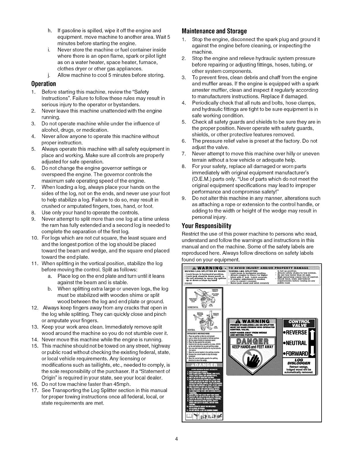
YourResponsibility
Restrict the use of this power machine to persons who read,
understand and follow the warnings and instructions in this
manual and on the machine. Some of the safety labels are
reproduced here. Always follow directions on safety labels
found on your equipment.
MOVING LOG SPLITTER BY HAND: TOWING LOG SPLITTER: _. tu. up position,
• Attach safety chains to tow vehicle
• Lock beam in horizontal position, _ Leek beam In horizontal position,
Attach coupler to Class I or higher • De not tow taster than 45 mph,
• Lock jack stand in down positi n. hitch with 2- ball, Latch securely. High speed may cause loss of control,
• Do not attempt to move Io splitter
.p or down a slope by han*_ It coupler adjustment is n_ded, • Check Iocal_ state and federal
refer to owner's manual, requirement s before t owing on any
$32422 • Raise Jack stand and latch securely public roa*t,
_e_Toe-s 'I+STeUCTIO+aS
,REVERSE
,NEUTRAL
LOG
DISLODGER
Retract wed
IO_led wooe _ be


