Page is loading ...

EMAX Compressor
1000 Cass Dr., Clayton, OH 45315 USA
866.294.4153
info@emaxcompressor.com
Fax: (937) 540-1157
Stationary Air Compressor
Operating Instructions
EMAX designs and manufactures products for safe
operation. However, operators and maintenance per-
sons are responsible for maintaining safety. All safety
precautions are included to provide a guideline for
minimizing the possibility of accidents and property
damage while equipment is in operation.
Keep these instructions for reference.
Model # :
UPC:
HI05V08Y1/HS05V08Y1 man
v.190811
HI05V08Y1 / HS05V08Y1
815002014265 / 815002014272

2
HULK Power
Model Specifications
● Model: HI05V08Y1
HS05V08Y1 (with noise suppression)
● Motor: 230
V (+ or - 10%) ~ 60
Hz, Single Phase
● No-load motor speed: 1750 rpm
● Power: 5
HP
● 2 stage, 3 cylinder, cast-iron piston pump
● Max. pressure: 155 psi
● No-load pump speed: 790 rpm
● Pump oil capacity: 2 quarts (1.9 liters)
● Air delivery:
18 cfm @ 100 psi
16.5 cfm @ 155 psi
● Tank size: 80 gal. (302.8 L)
● Tank outlet: 3/4"
● Weight- HI05V08Y1: 485 lb. (220 kg)
HS05V08Y1: 558 lb. (253 kg)
● Complies with CCR462 (L)(2).
Contents
Model Specifications ………………………… 2
Inspection ………………………………………… 3
Description ……………………………………… 3
Get to know your compressor ………………… 3
Safety Information …………………………… 4
Basic Guidelines ……………………………… 5
Breathable Air ………………………………………5
Pressurized Components ………………………5
Personal Protective Equipment ………………5
Installation ……………………………………… 6
Area ……………………………………………………6
Electrical Safety ……………………………………6
Operation ………………………………………… 7
Safety Rules …………………………………………7
Air Tool Cautions …………………………………7
Getting Started ………………………………… 8
Power Source Connection ………………… 8
Power Requirements ……………………………8
Grounding Instructions …………………………8
Assembly ………………………………………… 8
Operation ………………………………………… 8
Before operating your air compressor: …8
General Overview ……………………………… 9
Installation and Location ………………………9
Air Intake ……………………………………………9
Pipe Connection ……………………………………9
Starting …………………………………………… 10
Pressure Switch ……………………………………10
Adjusting the air pressure ……………………10
Shutting off your compressor …………………10
Cold Weather Starting …………………………… 10
Maintenance …………………………………… 10
Service …………………………………………………10
Daily ……………………………………………………11
Weekly …………………………………………………11
Monthly ………………………………………………11
Troubleshooting ……………………………… 11
Slow Pumping Or Insufficient Pressure …11
Overheating …………………………………………12
Storage …………………………………………………12
Troubleshooting Chart ……………………… 13
Hulk Warranty Statement ………………… 14
READ INSTRUCTION MANUAL BEFORE OPERATING.
In order to receive maximum performance and long life from your compressor, the following instructions
should be read carefully and all points regarding installation and operation of the unit should be noted and
observed. Carefully reading this manual before connecting anything to the motor or compressor is necessary
for optimum trouble-free operation.

3
HI05V08Y1/HS05V08Y1 man
v.190811
Stationary Air Compressor
Inspection
● Inspect compressor prior to any use.
● Check for external damage that might have occurred during transit. Check for possible damage from
transit and test the pulley by turning it freely with your hands. Be careful of moving parts.
● Report any damage to delivery carrier immediately.
Do not operate unit if damaged during shipping, handling or use. Damage may result
in bursting and cause injury or property damage.
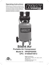
Description
Get to know your compressor
Please refer to g 1 and 2.
1. TANK DRAIN VALVE
(located on bottom of tank) - The tank drain
valve can be opened to allow moisture and
compressed air to be released from the air tank.
The tank drain valve should
always be opened slowly to
avoid damage to equipment and possible injury.
fig 1
13
3
3
3
2
2
7
7
4
5
6
8
9
10
12
11
13
1414
15
16
17
18
20
21
2. AIR TANK -
eighty gallon (302.8 liters) tank
3. FOOT
Allows fastening to the oor, reduces
compressor tip danger, vibration and movment.
1/4" thick vibration isolator must
be used.
4. SAFETY VALVE -
The safety pressure relief valve automatically
relieves pressure from the air tank in the event

4
HULK Power
4
of excessive pressure build up. The safety valve
is preset at factory. Do not attempt to make any
adjustments to the safety valve. Periodically pull
the ring on the safety valve end to check that it
is working properly.
5. RESERVOIR AIR PRESSURE GAUGE -
Indicates pressure of compressed air built up in
the tank.
6. PRESSURE SWITCH -
Turns the air compressor on and o and will
start the compressor pump automatically when
tank pressure is below the factory-set minimum.
The pressure switch continues to monitor the
pressure and turns the pump o when the
pressure reaches the factory-set maximum.
Always make sure that the
compressor power is in the OFF
position before performing any maintenance or
plugging the compressor into a power supply.
7. AIR FILTERS -
Ensures the air being pressurized is free of
contaminants and reduces the amount of noise
the pump generates.
Air lters are mounted in Whisper 100 (19, g.2),
on units that have the Whisper Silencer.
8. PUMP OUTPUT AIR TUBE -
Conducts the compressed air to the tank as it
leaves the compressor pump.
9. SIGHT GAUGE -
Allows easy viewing of your air compressor
pump's oil level.
10. PUMP CYLINDER -
Where the air is pressurized.
11. MOTOR
12. CONNECTION BOX -
A place to make connection to electrical power
for the air compressor.
13. MOTOR WIRING BOX AND CAPACITORS-
Vary the connection to electrical power for the
air compressor.
14. BELT AND PULLEY GUARD
15. DRIVEN PUMP PULLEY / FAN
16. DRIVE PULLEY
17. TANK (PRESSURE VESSEL) ASME/CRN
CERTIFICATION PLATE
18. MOUNTING BRACKET FOR "WHISPER" NOISE
SUPPRESSION SYSTEM.
19. "WHISPER" NOISE SUPPRESSION SYSTEM
mounted (HS05V080Y1- g 2). Houses air
pre-lters and compressor air lters, which
require routine maintenance.
fig 2
19
20. TANK ACCESS PLUG
21. TANK OUTLET WITH BALL VALVE SHUT-OFF
Safety Information
This manual contains very important information to
know and understand. This is provided for SAFETY
and to PREVENT EQUIPMENT PROBLEMS. To help
understand this information, observe the following:
Danger indicates an imminently
hazardous situation which, if not
avoided, will result in death or serious injury.
Warning indicates a potentially
hazardous situation which, if not
avoided, could result in death or serious injury.
Caution indicates a potentially
hazardous situation which, if not
avoided, may result in minor or moderate injury.
Notice indicates important
information, that if not followed, may
cause damage to equipment.
Read all manuals included with this
product carefully. Be thoroughly
familiar with the controls and the
proper use of the equipment.
MANUAL

5
HI05V08Y1/HS05V08Y1 man
v.190811
Stationary Air Compressor
CALIFORNIA PROPOSITION 65
This product or its power cord
may contain chemicals known to
the State of California to cause cancer and birth
defects or other reproductive harm. Wash hands
after handling.
Basic Guidelines
1. Allow only trained, authorized persons who
have read and understood these operating
instructions to use this compressor. Failure
to follow the instructions, procedures and
safety precautions in this manual can result in
accidents and injuries.
2. NEVER start or operate the compressor
under unsafe conditions. Tag the compressor,
disconnect and lock out all power to it to
prevent accidental start-up until the condition
is corrected.
3. Install, use and operate the compressor only
in full compliance with all pertinent OSHA
regulations and all applicable Federal, State &
Local Codes, standards and regulations.
4. NEVER modify the compressor and/or
controls in any way.
5. Keep a rst aid kit in a convenient place. Seek
medical assistance promptly in case of injury.
Avoid infection by caring for any small cuts
and burns promptly.
Breathable Air
1. This compressor/pump is NOT equipped
and should NOT be used “as is” to supply
breathing quality air. For any application of
air for human consumption, you must t the
air compressor/pump with suitable in-line
safety and alarm equipment. This additional
equipment is necessary to properly lter and
purify the air to meet minimal specications
for Grade D breathing as described in
Compressed Gas Association Commodity
Specication G 7.1 – 1966, OSHA 29 CFR
1910. 134, and/or Canadian Standards
Associations (CSA)
Death or serious injury can result
from inhaling compressed air
without using proper safety
equipment. See OSHA standards
on safety equipment.
2. DO NOT use air line anti-icer systems
in air lines supplying respirators or other
equipment used to produce breathable air.
DO NOT discharge air from these systems in
unventilated or other conned areas.
In the event the compressor is used for the
purpose of breathing air application and proper
in-line safety and alarm equipment is not
simultaneously used, existing warranties are
void, and EMAX Air Force Technology disclaims
any liability whatsoever for any loss, personal
injury or damage.
Pressurized Components
RISK OF BURSTING – do not
adjust regulator to result in
output pressure greater than marked maximum
pressure of attachment. If a regulator has not
been installed. Use only attachments rated at 200
psi or higher. Do not weld on or repair tank –
replace. Do not operate without proper asme
safety valve in place.
1. This equipment is supplied with a ASME
designed pressure vessel protected by an
ASME rated relief valve. Pull the ring before
each use to make sure the valve is functional.
DO NOT attempt to open valve while the
machine is under pressure.
2. Improper maintenance could lead to the air
tank bursting or exploding.
3. Drain air tank after each use or
every day to prevent corrosion due to
moisture buildup in the air tank. Rust
can weaken the air tank and cause
leaks or bursting. If rust is detected, replace
tank immediately.
4. Do not attempt repairs to the air tank by
welding, drilling or other modications. Such
modications may weaken the air tank and
cause a hazardous condition.
5. If the air tank develops a leak, replace it
immediately. Never repair, weld or make
modications to the air tank or its attachments.
6. Do not make adjustments to the factory-set
pressures.
7. Never exceed attachments' manufacturer's
maximum-allowable pressure rating.
8. Do not use plastic pipe or lead tin solder
joints for a discharge line as the may not
withstand the high heat developed during air
compression.
Personal Protective Equipment
Be sure all operators and others around the
compressor and its controls comply with all
applicable OSHA, Federal, State and local
regulations, codes and standards relating to
personal protective equipment. This includes
respiratory protective equipment, protection for
the extremities, protective clothing, protective
shields and barriers, electrical protective
equipment, and personal hearing protective
equipment.
1. Eye protection should be worn at all times
when operating this tool. Use ANSI approved

6
HULK Power
safety glasses. Everyday eyeglasses are NOT
safety glasses. Dust mask, non-skid safety
shoes, hard hat, or hearing protection should
be used in appropriate conditions.
2. Wear proper apparel.
Loose clothing, gloves, neckties, rings,
bracelets, or other jewelry may present a
potential hazard when operating this tool.
Please keep all apparel clear of the tool.
Installation
Area
1. Install compressor in a clean, dry and well-lit
area. Be sure installation area can maintain a
temperature range between 35° - 110° F (2° -
43° C).
2. Do not use below garage oor or grade level
If ambient temperature drops
below 32˚F (0° C), be sure to
protect safety/relief valves and drain valves from
freezing. NEVER operate compressor with
temperatures below 15˚F (-9.5° C) or above 125˚F
(52° C).
3. Allow sucient space around compressor for
maintenance access and adequate airow.
Mount unit leaving a minimum of 15 inches (38
cm) of clearance.
4. Use 1/4" rubber shims to level compressor
if installation area is not at. This will avoid
excessive vibration and premature pump wear.
DO NOT use shims thicker than
1/4". Thicker shims can cause
tank damage.
DO NOT install compressor in
boiler room, paint spray room, or
area where sandblasting occurs. Make sure inlet
air is away from exhaust fumes or other toxic,
noxious or corrosive fumes or substances.
RISK OF FIRE OR EXPLOSION
– do not spray combustible/
ammable liquid in a conned area. spray area
must be well ventilated. do not smoke while
spraying or spray where spark or ame is
present. arcing parts – keep compressor at least
20 feet away from spraying area and all explosive
vapors.
5. If acid is used in operating environment or air
is dust laden, pipe intake to outside, fresh air.
Increase pipe size by one size for every 20
feet of run. Be sure to install protective hood
around intake lter.
6. Insulate cold water or other low temperature
pipes that pass overhead to avoid
condensation dripping on compressor which
could cause rust and/or motor shorting.
Electrical Safety
Be sure only trained and
authorized personnel maintain
this compressor in accordance
with all applicable federal, state
and local codes, standards and
regulations. Follow all NEC
(National Electric Code) standards especially
those concerning equipment grounding
conductors.
1. Follow all NEC and local codes for electrical
wiring. Allow only authorized Polar Air service
person or certied electrician to install
electrical components.
2. Put unit on dedicated circuit and make sure
no other electrical equipment is wired into it.
Failure to wire unit on independent circuit can
cause circuit overload and/or imbalance in
motor phasing. Install proper No Fuse Breaker
(NFB) according to kW output of compressor.
3. Ensure incoming service has adequate
ampere rating.
4. Ensure supply line has the same electrical
characteristics (voltage, cycles and phase) as
the electric motor.
5. Refer to amp load information on the
specications label and use correctly sized
wiring. Be sure to consider distance between
power supply and machine.
6. Install surge protection device between power
supply and compressor motor.
7. Make sure to install properly sized breakers
and fuses.
8. The unit must be properly grounded. DO NOT
connect ground wire to air or cooling lines.
9. If the tool is equipped with three-pin plug, it
should be plugged into a three-pin electrical
socket. Never remove the ground pin.
10. Avoid body contact with grounded surfaces
such as pipes, radiators, ranges, and
refrigerators. There is an increased risk of
electric shock if your body is grounded.
11. To reduce the risk of electrical shock or injury,
do not expose tool to moisture.
Don’t use this tool in damp or wet locations.
Keep out of rain.
12. Do not abuse cord.
Never use the cord to carry tools or pull the
plug from an outlet. Keep cord away from
heat, sharp edges or moving parts. Check
for damage and replace damaged cords
immediately before connecting to power
supply. Damaged cords increase the risk of
electric shock.

7
HI05V08Y1/HS05V08Y1 man
v.190811
Stationary Air Compressor
13. Always disconnect the tool from power source
before making any adjustments, storing,
servicing, or changing accessories. Such
preventative safety measures reduce the risk
of starting the tool accidentally.
14. Keep away from ammables.
Do not attempt to operate this tool near
ammable materials or combustibles. Failure
to comply may cause serious injury or death.
Operation
Safety Rules
1. Make sure all operators receive product
training, read and understand all instructions.
Keep all ammable, combustible,
poisonous and noxious materials
away from operating area. Make
sure there are no oily rags, trash,
leaves, litter or other
combustible materials in
operating area. Keep suitable, fully charged re
extinguishers nearby when servicing and
operating the compressor.
2. NEVER allow modications to compressor
structure or controls.
3. Keep all ignition sources away from exposed
electrical parts.
4. Keep all persons clear of compressor during
start-up and operation.
5. NEVER operate the compressor with the fan,
coupling or other guards removed.
6. DO NOT engage in horseplay with air hoses
as death or serious injury may result.
7. Make sure to provide adequate ventilation
while operating the compressor. If combustible
substances are spilled, clean up immediately.
8. When checking or when relling air line anti-
icer systems with antifreeze compound, shut
o compressor and allow it to cool. Keep
sparks, ames and other ignition sources
away and DO NOT permit smoking in the
vicinity.
9. Stop compressor and disconnect power if a
hazardous condition arises.
10. Wear snug tting clothing and conne long
hair when around compressor. Keep all body
parts and clothing away from couplings,
ywheel and other moving parts of the
equipment.
RISK OF INJURY – do not direct
air stream at body. Use eye
protection. Compressor starts automatically.
Moving parts. Do not touch. Keep guards in
place. Compressor does not supply breathable
air.
Keep all persons away from the
discharge opening of hoses or
tools or other points of
compressed air discharge. If the
machine is installed in an
enclosed area, be sure to vent
the relief valve outside of the structure or to an
unoccupied area.
Always make sure main power is
o before touching moving parts
of compressor.
11. Never exceed the pressure rating of any
component in system.
12. Protect material and air lines from damage or
puncture. Keep hose and power cable away
from sharp objects, moisture, chemicals, oil,
etc.
13. Check condition of hoses before each use.
Do not use a damaged hose. If hose is
damaged, replace immediately.
14. Read, understand and comply with all warning
labels on unit.
15. Drain tank of moisture after each use.
If compressor is not to be used for extended
periods of time, leave tank drain valve open to
allow moisture to completely drain from tank.
16. Do not tamper with Safety Valve. The
Safety Valve is factory set for your model air
compressor. Any user adjustments to Safety
Valve will automatically void warranty.
17. Air compressors get hot while in operation.
NEVER touch the motor, the
discharge tubing or compressor
pump while in operation.
18. The compressor turns itself on and o
automatically while the pressure switch is
turned on.
19. The air pressure switch is set at the factory
for optimum performance of your equipment.
Never attempt to bypass or remove this switch
as serious damage to equipment or personal
injury could result from excessive air pressure.
20. Compressed air from the unit may contain
carbon monoxide. Air produced is not suitable
for breathing purposes.
21. Always use a respirator when spraying paint
or chemicals.
Air Tool Cautions
1. DO NOT use air tools that are rated below the
maximum rating of the compressor. Select
air tools, air hoses, pipes, valves, lters and
other ttings accordingly. DO NOT exceed
manufacturer’s rated safe operating pressures
for these items.

8
HULK Power
2. Make sure all hose connections are
adequately secured to prevent tools or hose
ends from being accidentally disconnected.
3. Remove adjusting keys or wrenches before
turning the tool on. A wrench or key that is
left attached to a moving part of the tool may
result in personal injury.
4. Keep work area clean and well lit.
Cluttered or dark work areas invite accidents.
5. Keep children away.
All children should be kept away from the work
area. Never let a child handle a tool without
strict adult supervision.
6. Store idle tools out of the reach of children and
untrained persons.
Tools may be dangerous in the hands of
untrained users.
7. Do not operate any tool if under the inuence
of alcohol or drugs.
Read warning labels on prescriptions to
determine if your judgment or reexes are
impaired while taking drugs. If there is any
doubt, do not attempt to operate.
8. Do not force tool.
Use the correct tool for your application. The
correct tool will do the job better and safer at
the rate for which it was designed.
9. Do not use the tool if the switch does not turn
it on and o.
Any tool that cannot be controlled with the
switch is dangerous and must be repaired.
10. Check for damage.
Check your tool regularly. If part of the tool
is damaged it should be carefully inspected
to make sure that it can perform its’ intended
function correctly. If in doubt, the part should
be repaired. Refer all servicing to a qualied
technician. Consult your dealer for advice.
11. Maintain tools with care.
Keep tools sharp and clean. Properly
maintained tools, with sharp cutting edges, are
less likely to bind and are easier to control.
Getting Started
Unpack your compressor.
Before operating your tool, check the contents of the
box to make sure you have everything you will need.
Items included in the box:
● Air Compressor
● Owner’s Manual
Save packaging in case you need to
return the compressor for servicing or
repair.
Power Source Connection
Power Requirements
This equipment is designed to operate on a properly
grounded 230 volt, 60 Hz, single phase alternating
current (AC) power source. If connected to a circuit
protected by fuses, use time-delay fuse marked “D”.
Installation should be executed by a licensed
electrician who should verify the ACTUAL VOLTAGE
of the circuit into which the tool will be connected
and that it is properly grounded.
A 230 volt motor will not work suciently on a
nominal 208 volt system. Even if the actual voltage
is up to 208 volts, the 10-12 volt drop during start
up (this is an average, but not a high gure for
commercial buildings) may cause the motor to
labor and blow fuses or heater elements. Do not
accept the nominal gure for line voltage, but rather
measure it with a voltmeter during a period of
maximum power demand.
The use of the proper circuit size can eliminate
nuisance circuit breaker tripping when using your
tool. Improper performance, and/or, damage to
the tool will result if operated on inadequate, or
excessive power.
Wiring should be installed by a licensed electrician
who is familiar with requirements of the National
Board of Fire Underwriters and of the local
inspectors is recommended. Consult your local
electrical contractor regarding electric codes and
recommended wire sizes.
DO NOT OPERATE THIS TOOL if
the ACTUAL power source
voltage is less than 215 volts AC or greater than
230 volts AC.
Grounding Instructions
● In the event of an electrical malfunction or short
circuit, grounding reduces the risk of electric
shock. The motor of this machine is wired for
230 V single phase operation and must be
hard-wired into your electrical panel.
● All electrical connections must be tightened
before starting. This includes connections at the
Magnetic starter. This shall include all factory
connections.
● Repeat: Check all electrical connections before
startup.
RISK OF ELECTRICAL SHOCK –
hazardous voltage: disconnect
from power source before servicing. Compressor
must be grounded. Do not use grounding
adaptors. Do not expose to rain. Store indoors.
Assembly
Before performing any assembly or
maintenance, make sure compressor
is turned o and unplugged from the power
supply.
Place compressor on a level surface. It is top-heavy
and must be fastened securely to the oor.
Operation
Before operating your air compressor:
● Inspect for damage before using the air
compressor, make sure the air tank is not
damaged, inspect all parts for damage, and

9
HI05V08Y1/HS05V08Y1 man
v.190811
Stationary Air Compressor
check that all pipes and hoses are rmly
connected.
● Do not use the air compressor if any damage is
found. If damaged, have an authorized service
center inspect and test the air compressor to
ensure that is working properly.
● Pull the ring on the safety valve before each use
to make sure the valve is functional.
● Depending on the CFM draw of the tools being
operated, your new air compressor can be used
for operating paint sprayers, air tools, grease
guns, airbrushes, caulking guns, abrasive
blasters, tire & plastic toy ination, spraying
weed killer and insecticides, etc. Proper
adjustment of the air pressure regulator is
necessary for all of these operations. Refer to
the air pressure specications provided with the
tool you are using.
General Overview
Installation and Location
● Locate the compressor in a clean, dry and
well ventilated area. In cold climates, the
compressor should be installed in a heated
building. Compressor should be located in a
temperature-controlled area between 32° and
95° fahrenheit (0° and 35°C).
● Insulate cold water or other low temperature
pipes that pass overhead to avoid possible
collection and dripping of condensate onto the
compressor and motor that could cause rust
and/or motor shorting.
● Do not install the compressor in a boiler room,
paint spray room, or area where sandblasting
occurs. If acid or dust is in the air where the
compressor is operating, the compressor intake
should be piped to the outside. This intake pipe
should be increased one pipe size for every
twenty (20) feet of run and the intake lters
should be installed at the end of the pipes with
a hood to protect them from the elements.
Special size lters are required for pipe away.
● If the compressor has to be located where the
motor will be exposed to appreciable quantities
of water, oil, dirt, acid, or alkaline fumes, the
motor must be of special construction to avoid
rapid deterioration; i.e. TEFC
● Place the compressor on a rm, level surface.
Unless the base is exactly level, shims will
probably be required. Any space between
base and foot should be shimmed rather than
drawing the foot down, thus placing strain
on the unit. When unit is properly shimmed,
vibration will be at a minimum.
Tank feet should be placed on
vibration isolator pads (1/4’’ thick or
less) available through your dealer. Anchor bolts
should be gently snug, but not tight, to allow for
vibration. Remember, the bolt is only a guide to
hold the compressor in place. Do not over
tighten the legs of the tank against the pads…it
will damage your tank.
Keep unit level and be
careful of top-heavy load
fig.3
Do not store tank on dirt or on an
uneven surface. Over time, the
tank will tilt causing pump failure from no
lubrication.
● Allow sucient space around the compressor
so that it is accessible from all sides for
maintenance. Mount the unit with the pulley
towards the wall at least 18 inches (45 cm)
between pulley & wall.
● The compressor should be located 12 to
18 inches (30 to 45 cm) from walls or any
other obstruction which would interfere with
airow. The compressor is designed with heat
dissipation ns which allow for proper cooling.
Keep the ns (and all other parts which collect
dust or dirt) clean. A clean compressor runs
cooler and provides longer service. Do not
place rags, containers or other material on top
of the compressor.
Air Intake
The compressor is equipped with an intake lter
that requires no piping. If it is necessary to pipe
the intake to the outdoors, see the section above,
“Installation and Location”.
Pipe Connection
A exible connector should be used between the
compressor tank and the building air system piping
or connection to the after cooler or other similar
equipment in order to minimize noise, vibration,
vibration damage and wear and tear.
Never install a shut-o valve (e.g.
glove or gate valve) between the
compressor discharge opening and the receiver
unless a safety valve is installed in the line
between this valve and the compressor.
Never operate the pump at a
pressure or a speed in excess of
those recommended by the factory.
Use only air hoses rated for use with
155 psi air pressure or higher.

10
HULK Power
Starting
● Check oil level before starting. The oil should be
in the center of the sight glass.
● Turn the compressor over a few revolutions by
hand to make sure that everything is free.
● Check belt tension. (should be ½’’ of play).
● Remove rags, tools, and any other objects from
the vicinity of the compressor. Never put hands
on the belts of an idle unit unless you are sure
the main motor switch is o. Note the direction
of the arrow stated on the belt guard and
be sure rotation is the same direction when
running. Correct direction is counter-clockwise
when standing facing the ywheel. Air should be
drawn through the intercooler onto the cylinders
for maximum cooling.
● Drain Valve: Make sure the tank drainage valve is
closed and not in the open position.
Pressure Switch
● Ensure that the power supply you are going to
use is operating normally.
● Turn the power on.
● On the reservoir pressure gauge, you can watch
pressure build in the tank until the pump stops
at the factory-set pressure, about 150 psi.
● This rst time running your compressor and
periodically thereafter, check for air leaks. If
the gauge indicates pressure is going down in
the tank or you hear leakage, you could apply
Oil level should be to
center of red circle in
sight glass while in the
OFF position
fig.4
fig.5
1/2”
soapy water to all joints in the air transport
piping. Tighten these joints if bubbles form.
Adjusting the air pressure
Use an air pressure regulator (not supplied). This
regulator adjusts the air pressure supplied to the
piping system.
• To increase or decrease air pressure, turn air
regulator knob in the direction indicated by the
manufacturer.
• Use an outlet pressure gauge (not supplied)
mounted downstream from the regulator to
see the resulting pressure.
Shutting off your compressor
1. Move the power switch to the OFF position (g
8.0).
2. Disconnect the compressor from the electical
power.
3. If not draining the tank, reduce air pressure
through the air hose.
4. Drain the tank by slowly opening the drain valve.
Place a catch basin under the valve to protect the
surface from water damage.
Cold Weather Starting
Temperatures below freezing (32 °F / 0 °C) cause
the metal parts of your air compressor to contract
and that makes starting more dicult. To assist the
air compressor in starting in cold weather, follow
these tips:
1. Try to keep the air compressor stored in
temperatures above 32 °F (0 °C).
2. Open the air tank drain valve and release all air
pressure from the air tank before attempting to
start in cold weather. (After air is released from air
tank, close drain valve.)
3. Pull the ring on the safety valve before each use
to make sure the valve is functional.
Maintenance
Service
● All units are shipped with break-in oil and must be
changed after the rst 50 hours to insure gasket
seating.
● Thereafter, oil should be changed every 3 months
or 1000 hours; whichever occurs rst.
● Always maintain proper oil level in unit. If the unit
runs out of oil due to neglect the warranty will
void.
● Use only EMAX approved oils in your
compressor, or your warranty is void.
DO NOT use automotive-type oil.
Oil level should be halfway level in the sight glass
when unit is o.
● If oil is milky an oil change will be required.

11
HI05V08Y1/HS05V08Y1 man
v.190811
Stationary Air Compressor
Daily
● Before each use,
1. check for any unusual noise or vibration.
2. be sure all nuts and bolts are tight.
● After each use, drain condensation from the air
tank.
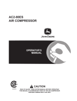
Weekly
● Inspect air lters (g.6) weekly and clean or
change as needed.
● For HS05V080Y15 compressors, with the
"Whisper 100" Noise Suppression System
mounted (g.7), to access and replace silencer
lter elements:
1. Remove thumb screws from front of Silencer
2. Remove Silencer access panel
3. Remove lter wing nuts
4. Remove lter covers
5. Remove lter elements
6. Clean or change as needed.
Monthly
● Inspect air system for leaks by applying soapy
water to all joints. Tighten these joints if leaks
are discovered.
Housing
Access
Panel
Filter Cover
Filter Element
Wing Nut
Thumb
Screw
fig.7
Troubleshooting
Always inspect the compressor before use, and
make sure it is in good working condition. Make
sure all air vents are clear. Check the power cable
to make sure it is intact and free from cracks, bare
wires etc. Avoid using solvents when cleaning plastic
parts, most plastics are susceptible to damage from
the various types of commercial solvents.
Belt Adjustment
● Always pull the motor disconnect switch before
working on the belts so the motor cannot start
up unexpectedly.
● When belt tension is adjusted properly, the belts
can be depressed at a point midway between
the motor pulley and the ywheel approximately
one half inch. Loose belts will slip on the motor
pulley and cause excessive heating and wear. A
belt that is too tight will overload the bearings.
● Adjustments can be made by sliding the motor
along its base.
● When installing new belts, it is necessary that the
motor bolts be loosened and the motor moved
toward the compressor. The new belts can be
installed without damage or strain. Over time
belts stretch, and it is recommended that all
belts be changed at the same time.
Slow Pumping Or Insufficient Pressure
Can be caused by:
1. Clogged inlet lter (disassemble and clean
thoroughly).
2. Leaks in air lines, valves, ttings, etc. (Locate by
using soapy water if necessary; replace or tighten
threaded parts).
3. Compressor too small for equipment application.
Check air requirements vs. compressor capacity
and consult dealer.
4. Leaking head valves (remove hold-down covers
than remove valves for inspection. Repair or
replace faulty valves).
5. If the power network in the building is 208 volts,
order a 208 volt motor. If the starting voltage
is much less the 90% of the motor nameplate
voltage, the motor cannot be expected to start
and the interior building wiring must be corrected.
Belt tensioner
bolt head
Loosen motor
frame nuts (all
four mounts)
Awaiting new pic

12
HULK Power
Overheating
Compression of air generates heat, much of which is
dissipated as air passes over the intercooler and/or
after cooler.
Overheating can be caused by:
1. Pump running backwards (reverse direction).
Proper rotation is counter-clockwise when facing
the ywheel.
2. One or more head valves are failing to seat
properly.
3. Blown cylinder head gasket. Restriction in head,
intercooler, or check valve.
4. Lack of oil (check oil level).
5. Dirt in intercooler ns or cylinder ns-(blow out
with air).
6. Poor ventilation and ambient temperature is too
high where the compressor is stored.
Storage
When storing your compressor:
1. Be sure the unit is turned OFF.
2. Remove it from power source.
3. Rotate the regulator to set the outlet pressure to
zero.
4. Release air pressure from all hoses and air
tank(s).
5. Drain all moisture from air tank(s).
6. Fully close drain valve(s).
7. Protect electrical cabling and air hoses from
damage (such as being stepped on or driven
over). Wrap all cords and hoses loosely around
the (cooled) air compressor.
8. Place air compressor in a cool, dry, safe, and
indoor location.

13
HI05V08Y1/HS05V08Y1 man
v.190811
Stationary Air Compressor
Troubleshooting Chart
Trouble Possible Cause Corrective Action
Compressor will not start 1. Blown fuse or circuit breaker
tripped
1. Replace or reset fuse/circuit breaker
2. Loose electrical connections 2. Check wiring connnections
Low pressure 1. Restricted air lter 1. Replace air lter
2. Defective check valve 2. Replace check valve
3. Air leak in safety valve 3. Check valve by pulling on ring. If
condition persists, replace valve
Safety valve releases Defective pressure switch Replace pressure switch
Pressure in tank falls 1. Air leaks at joints 1. Allow the compressor to build pres-
sure in the tank, to the max pressure if
possible. Spray or brush soapy water
on all air connections and look for bub-
bles. Tighten leaky connections. Do not
over-tighten.
2. If the problem continues, contact
customer support for further advice.
Unloader valve leaks when
pump is not running
Unloader valve seal defective Allow air in the air tank out until all
pressure is released. Remove the un-
loader valve plug and clean the valve
seal. If damaged, replace seal and
re-install.
Compressor stopped and will
not re-start
1. Thermal overload protector has
engaged due to motor overheat-
ing
1. Check that the main supplied
voltage corresponds to the compres-
sor specications. An inadequate
extension cord (too thin or too long)
can cause the motor to overheat due
to voltage drop. Excessive use (over
1 hour continuous) can cause motor
overheating. Allow the motor to cool
down.
2. Motor windings burn-out Contact customer support
Motor does not start and
makes a humming sound
Capacitor burn-out Contact customer support
Motor does not start or starts
slowly
Low voltage electrical supply to
motor
Check that the main supplied voltage
corresponds to the compressor speci-
cations.
An inadequate extension cord (too thin
or too long) can cause the motor to
overheat due to voltage drop.
Check power quality at outlet
Compressor runs noisily and
metallic sounds are heard
Compressor will not come to
max pressure
Head gasket or reed valve dam-
aged.
Stop the compressor and contact cus-
tomer support
Compressor doesn’t provide
as much air as when new
and/or cuts o after a much
shorter time period.
1. Tank has reduced capacity due
to water retention
2. Pressure switch is out of adjust-
ment
1. Open drain valve to release water
2. Contact customer support
Pump unit does not stop
when the tank reaches maxi-
mum working pressure.
Defective or pressure switch out
of adjustment
Stop the compressor immediately (risk
of explosion) and contact customer
support

14
HULK Power
Hulk Warranty Statement
Hulk Power by EMAX Compressor makes the following Warranty guarantee:
● Standard warranty: That each compressor unit is free from defects in material, workmanship, and
parts for 1 year from the date of purchase. Hulk Power by EMAX is not reasonable for downtime during
warranty service. If downtime is necessary, it is the purchaser’s discretion and obligation, at purchases
expense, to have a redundant compressor. Warranty repair parts shall only include freight charges for
the rst 90 days of the warranty, there after purchase is reasonable for freight charges for warranty
parts.
*Required maintenance schedule to maintain warranty status
a. All units are shipped with break-in oil and must be changed after the rst 50 hours to insure
gasket seating.
b. Thereafter, oil should be changed every 3 months or 1000 hours whichever occurs rst
c. Always maintain proper oil level in unit. If the unit runs out of oil due to neglect, the warranty will
void.
d. Use only EMAX-approved oils in your compressor, or your warranty is void.
● Extended warranty: Hulk Power by EMAX will extend your 1-year warranty by 3 years, for a total of 4
years of warranty coverage when you opt to register for the extended warranty plan.
To register your warranty and nd the extended warranty options, go to www.emaxwarranty.com. Details
and options for our extended warranty will be provided online once you enter the required information.
● Choose the new SMART OIL™ maintenance kit option to extend your Hulk by EMAX air compressor
pump up to 8 years of coverage! SMART OIL™ not only extends the life of your compressor pump, it
also can reduce operating noise and can creates further energy savings.
● Exclusions include * service such as oil changes, lter replacements, gasket tightening to correct oil
seepage or drive belt tightening and valve cleaning and are not covered under warranty.
Warranty shall be voided under the following conditions: Failure to routinely change oil and to
maintain clean ltration or exceeding 70% duty cycle resulting in overheating and excessive wear and
tear. Exposing electrical components to rain or water, or installing the unit in a hostile environment
such as acid vapors or any caustic or abrasive matter that may be ingested into the pump, or installing
the unit in an enclosed area where lack or cooling ventilation if present, such as in boiler or equipment
rooms where the ambient air exceeds 100° F
Parts used for warranty purposes must be supplied by EMAX, Inc. Warranty work will be performed be
an approved EMAX, Inc Technician. If any maintenance (other than routine maintenance) is performed
by a non-approved EMAX, Inc. Technician, written pre-approval must be obtained from EMAX, Inc to
prevent voiding this warranty. Failure to fully comply with this warranty and fully comply with the manual
herein will void this warranty.
*All warranties are non-transferable
The oil purchase program is eective as of July 1, 2019
/