Page is loading ...

Sapling, Inc. 1633 Republic Road Huntingdon Valley, PA 19006 Phone: (215) 322-6063 Fax: (215) 322-8498 www.Sapling-Inc.com
SBD 2000 Series Digital Clock Installation Manual (V5)
Page 1
Table of Contents
MOUNTING
Flush Mount Installation……………………………………………………………........ Page 2
Wall Mount Installation ……………………...…………….…………………………... Page 3
Double Mount Installation…………………………..………………………………….. Page 4
WIRING AND JUMPERS
Wiring Information and Jumper Settings……………………………………………….. Page 5
WIRING DIAGRAMS
Wiring Diagrams………………………………………………………………………... Pages 6 - 19
INTERFACING
Interfacing With Other Systems…………………………………………………………. Pages 20 - 23
FREQUENTLY ASKED QUESTIONS
SBD 2000 Frequently Asked Questions...………………………………………………. Page 24
TROUBLESHOOTING
SBD 2000 Troubleshooting……………………………………………………………… Page 25

Sapling, Inc. 1633 Republic Road Huntingdon Valley, PA 19006 Phone: (215) 322-6063 Fax: (215) 322-8498 www.Sapling-Inc.com
SBD 2000 Series Digital Clock Installation Manual (V5)
Page 2
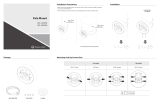
1. Mount the flush mount box into the wall.
2. Connect the ground wire into the flush mount box using the tooth lockwasher and
the machine screw nut (included in the kit).
3. Disconnect the red filter from the display panel.
4. Connect the wiring as shown on the wiring diagram.
5. IMPORTANT: If using a low voltage system (24 volt) make sure that the
transformer is an isolated transformer.
6. Mount the display panel into the flush mount box using the four (4) black machine
screws (#6, included in the kit). Make sure the switches are on the right side.
7. Snap the red filter into the display panel.
Flush Mount Installation
Instructions

Sapling, Inc. 1633 Republic Road Huntingdon Valley, PA 19006 Phone: (215) 322-6063 Fax: (215) 322-8498 www.Sapling-Inc.com
SBD 2000 Series Digital Clock Installation Manual (V5)
Page 3
1. Mount the wall mount box into the double gang box using four machine screws (#6-32)
including in the kit.
2. Connect ground wire into flush mount box using tooth lockwasher and machine screw
nut (included in the kit).
3. Disconnect the red filter from the display panel.
4. Connect the wiring as shown on the wiring diagram.
5. IMPORTANT: If using a low voltage system (24 volt) make sure that the
transformer is an isolated transformer.
6. Mount the display panel into the flush mount box using four (4) black machine screws
(#6, included in the kit). Make sure the switches are on the right side.
7. Snap the red filter into the display panel.
Wall Mount Installation
Instructions

Sapling, Inc. 1633 Republic Road Huntingdon Valley, PA 19006 Phone: (215) 322-6063 Fax: (215) 322-8498 www.Sapling-Inc.com
SBD 2000 Series Digital Clock Installation Manual (V5)
Page 4
1. Screw the hanger/mounting rod (included in the kit) into the crossbar (also in-
cluded in the kit).
2. Insert the wires through the hanger/mounting rod.
3. Install the crossbar using two (2) #6-32 screws into the double gang box.
4. Mount the double mount box into the clock base using two (2) #6 nuts and tooth
lockwasher #6. The double mount can be mounted either on the wall or on the
ceiling.
5. Insert the two (2) locking hole plugs (0.187”) and the locking hole plug (0.562”)
into the unused holes.
6. Insert the double mount case onto the hanger/mounting rod.
7. Insert the support bracket onto the hanger/mounting rod.
8. Screw the two (2) nuts (included in the kit) onto hanger/mounting rod and secure
the clock base to wall.
9. Connect ground wire into double mount box using the tooth lockwasher and
machine screw nut (included in the kit).
10. Disconnect the red filter from the display panel.
11. Connect the wiring as shown on the wiring diagram.
12. IMPORTANT: If using a low voltage system (24 volt) make sure that the
transformer is an isolated transformer.
13 Mount the display panel on one side of the double mount box using four (4) black
machine screws (#6, included in the kit). Make sure the switches are on the right side.
14. Snap the red filter into the display panel.
15. Repeat steps 9-13 for the second clock.
Double Mount Installation
Instructions

Sapling, Inc. 1633 Republic Road Huntingdon Valley, PA 19006 Phone: (215) 322-6063 Fax: (215) 322-8498 www.Sapling-Inc.com
SBD 2000 Series Digital Clock Installation Manual (V5)
Page 5
Wiring Information

Sapling, Inc. 1633 Republic Road Huntingdon Valley, PA 19006 Phone: (215) 322-6063 Fax: (215) 322-8498 www.Sapling-Inc.com
SBD 2000 Series Digital Clock Installation Manual (V5)
Page 6

Sapling, Inc. 1633 Republic Road Huntingdon Valley, PA 19006 Phone: (215) 322-6063 Fax: (215) 322-8498 www.Sapling-Inc.com
SBD 2000 Series Digital Clock Installation Manual (V5)
Page 7

Sapling, Inc. 1633 Republic Road Huntingdon Valley, PA 19006 Phone: (215) 322-6063 Fax: (215) 322-8498 www.Sapling-Inc.com
SBD 2000 Series Digital Clock Installation Manual (V5)
Page 8

Sapling, Inc. 1633 Republic Road Huntingdon Valley, PA 19006 Phone: (215) 322-6063 Fax: (215) 322-8498 www.Sapling-Inc.com
SBD 2000 Series Digital Clock Installation Manual (V5)
Page 9

Sapling, Inc. 1633 Republic Road Huntingdon Valley, PA 19006 Phone: (215) 322-6063 Fax: (215) 322-8498 www.Sapling-Inc.com
SBD 2000 Series Digital Clock Installation Manual (V5)
Page 10

Sapling, Inc. 1633 Republic Road Huntingdon Valley, PA 19006 Phone: (215) 322-6063 Fax: (215) 322-8498 www.Sapling-Inc.com
SBD 2000 Series Digital Clock Installation Manual (V5)
Page 11

Sapling, Inc. 1633 Republic Road Huntingdon Valley, PA 19006 Phone: (215) 322-6063 Fax: (215) 322-8498 www.Sapling-Inc.com
SBD 2000 Series Digital Clock Installation Manual (V5)
Page 12

Sapling, Inc. 1633 Republic Road Huntingdon Valley, PA 19006 Phone: (215) 322-6063 Fax: (215) 322-8498 www.Sapling-Inc.com
SBD 2000 Series Digital Clock Installation Manual (V5)
Page 13

Sapling, Inc. 1633 Republic Road Huntingdon Valley, PA 19006 Phone: (215) 322-6063 Fax: (215) 322-8498 www.Sapling-Inc.com
SBD 2000 Series Digital Clock Installation Manual (V5)
Page 14

Sapling, Inc. 1633 Republic Road Huntingdon Valley, PA 19006 Phone: (215) 322-6063 Fax: (215) 322-8498 www.Sapling-Inc.com
SBD 2000 Series Digital Clock Installation Manual (V5)
Page 15

Sapling, Inc. 1633 Republic Road Huntingdon Valley, PA 19006 Phone: (215) 322-6063 Fax: (215) 322-8498 www.Sapling-Inc.com
SBD 2000 Series Digital Clock Installation Manual (V5)
Page 16

Sapling, Inc. 1633 Republic Road Huntingdon Valley, PA 19006 Phone: (215) 322-6063 Fax: (215) 322-8498 www.Sapling-Inc.com
SBD 2000 Series Digital Clock Installation Manual (V5)
Page 17

Sapling, Inc. 1633 Republic Road Huntingdon Valley, PA 19006 Phone: (215) 322-6063 Fax: (215) 322-8498 www.Sapling-Inc.com
SBD 2000 Series Digital Clock Installation Manual (V5)
Page 18

Sapling, Inc. 1633 Republic Road Huntingdon Valley, PA 19006 Phone: (215) 322-6063 Fax: (215) 322-8498 www.Sapling-Inc.com
SBD 2000 Series Digital Clock Installation Manual (V5)
Page 19

Sapling, Inc. 1633 Republic Road Huntingdon Valley, PA 19006 Phone: (215) 322-6063 Fax: (215) 322-8498 www.Sapling-Inc.com
SBD 2000 Series Digital Clock Installation Manual (V5)
Page 20
Interfacing With Other Systems
58 Minute Correction
Description:
110 VAC/24 VAC 60 Hz is used to run the clock normally. See the SBD 2000 Programming
Manual for the four variations of 58 Minute Correction.
Instructions:
1) In programming mode, set option 31 to 02, 03, 04 or 05.
2) Connect interface harness as shown in the diagram.
Note: Manually set the slave clock to the time from the master clock upon initial connection.
After the slave clock receives its first daily correction, the clocks will be perfectly synchronized.
59 Minute Correction
Orange
Yellow
Blue
Gray
Purple
Brown
Red
Black
Orange
Yellow
Blue
Gray
Purple
Brown
Red
Black
110V Interface
Neutral
Reset
Neutral
Reset
24VAC Interface
Description:
110 VAC/24 VAC 60 Hz is used to run the clock normally. Applying an eight (8) second reset signal
from 57 minutes and 54 seconds will cause an hourly correction. Applying a fourteen (14) second reset
signal from 5:57:54 will cause a daily correction.
Instructions:
1) In programming mode, set option 31 to 01.
2) Connect interface harness as shown in the diagram.
Note: Manually set the slave clock to the time from the master clock upon initial connection. After
the slave clock receives its first daily correction, the clocks will be perfectly synchronized.
Orange
Yellow
Blue
Gray
Purple
Brown
Red
Black
Orange
Yellow
Blue
Gray
Purple
Brown
Red
Black
110V Interface
Neutral
Reset
Neutral
Reset
24VAC Interface
Orange
Yellow
Blue
Gray
Purple
Brown
Red
Black
N.O.
COM
Relay
Dry Contact Closure
Orange
Yellow
Blue
Gray
Purple
Brown
Red
Black
N.O.
COM
Relay
Dry Contact Closure
/


