Axing SKT 40-20M Operation Instructions Manual
- Category
- Modulator
- Type
- Operation Instructions Manual

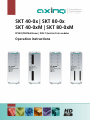
SKT 40-0x | SKT 80-0x
SKT 40-0xM | SKT 80-0xM
Multituner bzw. 8PSK/QPSK | DVB-T Quattro-/Octokassetten
Betriebsanleitung
Page is loading ...
Page is loading ...
Page is loading ...
Page is loading ...
Page is loading ...
Page is loading ...
Page is loading ...
Page is loading ...
Page is loading ...
Page is loading ...
Page is loading ...
Page is loading ...
Page is loading ...
Page is loading ...
Page is loading ...
Page is loading ...
Page is loading ...
Page is loading ...
Page is loading ...
Page is loading ...
Page is loading ...
Page is loading ...
Page is loading ...
Page is loading ...
Page is loading ...
Page is loading ...
Page is loading ...
Page is loading ...
Page is loading ...
Page is loading ...
Page is loading ...
Page is loading ...
Page is loading ...
Page is loading ...

SKT 40-0x | SKT 80-0x
SKT 40-0xM | SKT 80-0xM
8PSK/QPSK/Multituner | DVB-T Quattro/Octo modules
Operation instructions

Operation instructions | SKT 40-0x | SKT 80-0x | SKT 40-0xM | SKT 80-0xM
2 2017-01-26 | Technical changes, design modifications, errors and misprints are subject to change without prior notice.
Table of contents
1. Product description ...................................................................................................................................... 5
1.1. General ................................................................................................................................................ 5
1.1.1. Modules for DVB-S/S2 ................................................................................................................. 5
1.1.2. Modules with multituner for DVB-S/S2, DVB-T/T2 or DVB-C........................................................ 5
1.2. Scope of delivery.................................................................................................................................. 5
1.3. Inputs/tuner ......................................................................................................................................... 6
1.4. Output/modulators .............................................................................................................................. 7
1.5. Graphical user interface ....................................................................................................................... 7
1.6. Display elements and connectors ......................................................................................................... 8
1.6.1. SKT 40-0x | SKT 40-0xM .............................................................................................................. 8
1.6.2. SKT 80-0x | SKT 80-0xM .............................................................................................................. 9
2. Mounting and Installation .......................................................................................................................... 10
2.1. Mounting and installation in a headend base unit ............................................................................ 10
2.2. Mounting and installation stand alone .............................................................................................. 11
2.3. Equipotential bonding ....................................................................................................................... 11
2.4. Power supply ..................................................................................................................................... 12
2.5. Connection to DVB-S ......................................................................................................................... 12
2.5.1. Connection to the LNBs ............................................................................................................. 12
2.5.2. Multiswitches as input distributors ............................................................................................ 12
2.6. Connection to DVB-T/T2 or DVB-C ..................................................................................................... 12
3. Configuration ............................................................................................................................................. 13
3.1. Login and logout................................................................................................................................ 14
3.2. Front page ......................................................................................................................................... 15
3.2.1. Bit error rate .............................................................................................................................. 15
3.2.2. Fill level ..................................................................................................................................... 15
3.2.3. CI menus ................................................................................................................................... 15
3.2.4. Initialization .............................................................................................................................. 16
3.3. Initialization phase 1 ......................................................................................................................... 16
3.3.1. DVB-S (für 8PSK/QPSK- und für Multituner-Kassetten) .............................................................. 16
3.3.2. DVB-C, DVB-T or DVB-T2 (for multi tuner modules) .................................................................. 17
3.3.3. Bit error rate .............................................................................................................................. 18
3.3.4. Found programmes ................................................................................................................... 18
3.4. Initialization phase 2 ......................................................................................................................... 18
3.4.1. Remux mode ............................................................................................................................. 18
3.4.2. Scrambled programmes ............................................................................................................. 19
3.4.3. Cross Multiplex Mode................................................................................................................ 19
3.4.4. LCN (Logical Channel Numbering)............................................................................................. 21
3.5. Initialization phase 3 ......................................................................................................................... 22
3.5.1. Configuration of the modulator ................................................................................................. 22
3.5.2. Fill level ..................................................................................................................................... 23
3.5.3. Chosen programmes.................................................................................................................. 24
3.6. Maintenance ...................................................................................................................................... 25
3.6.1. Updating firmware/software ..................................................................................................... 25
3.6.2. Changing the IP address ............................................................................................................ 25
3.6.3. Changing the password ............................................................................................................. 26
3.6.4. Rebooting .................................................................................................................................. 26
3.6.5. Erasing service data................................................................................................................... 26
3.6.6. Save Initialization Data.............................................................................................................. 27
3.6.7. Upload Initialization Data .......................................................................................................... 27
3.6.8. Device name .............................................................................................................................. 28
4. Use of CA modules ..................................................................................................................................... 29
4.1. Insertion of CA modules .................................................................................................................... 29
4.2. CI menu for SKT 40-04 and SKT 80-02 ............................................................................................... 30
4.2.1. Using CI menu ........................................................................................................................... 30
4.3. Decryption of programmes ................................................................................................................ 31

2017-01-26 | Technical changes, design modifications, errors and misprints are subject to change without prior notice. 3
5. Technical data ............................................................................................................................................ 32
5.1. Input multituner ................................................................................................................................. 32
5.2. Input DVB-S/S2 tuner ......................................................................................................................... 32
5.3. Output/General .................................................................................................................................. 33

Operation instructions | SKT 40-0x | SKT 80-0x | SKT 40-0xM | SKT 80-0xM
4 2017-01-26 | Technical changes, design modifications, errors and misprints are subject to change without prior notice.
Safety instructions:
∂ The installation of the device and repair work on the device must be carried out only by a professional
in accordance with the applicable VDE directives. In case of incorrect installation, no liability is
assumed.
∂ Never open the device. There are no parts to be maintained by the user inside the device, however,
lethal voltages are present. This also applies to cleaning the device or working on the connections.
∂ Use only the mains cable connected to the device or the enclosed power supply unit. Never replace
any parts or make any modifications to the mains cable and the power supply unit. Otherwise, there
is a risk of death.
∂ If a replaceable fuse is available, pull out the mains plug before replacing the fuse. Replace defective
fuses only by standardized fuses with the same nominal value.
∂ If you intend not to use the device for a longer period of time, we recommend you to completely
disconnect the device from the mains for safety reasons and for saving energy by pulling out the
mains plug.
∂ Let the device adjust to the room temperature before commissioning, in particular if condensation is
present on the device, or if it was exposed to large temperature fluctuations.
∂ The device must be operated only in moderate climate.
∂ The device must be operated only in dry rooms. In damp rooms or outdoors, there is a risk of short-
circuits (attention: risk of fire) or electrical shocks (attention: risk of death).
∂ Plan the mounting or installation location such that you can easily reach the mains plug and interrupt
the electric circuit in dangerous situations. Select the mounting or installation location such that
children cannot play near the device and its connections without supervision. The mounting or
installation location must allow a safe installation of all connected cables. Power supply cables and
supply cables must not be damaged or squeezed by any objects.
∂ Select a mounting or installation location which meets the requirements of the IP 54 protection class.
Operate the device only on a flat, firm surface and protect it against unintentional movements.
∂ Never expose the device to direct solar irradiation and avoid direct vicinity of heat sources (e.g.
heaters, other electrical appliances, fireplace, etc.). It must be always ensured that devices with
cooling elements or ventilation slots are not covered or obstructed. In addition, ensure generous air
circulation around the device. This will prevent possible damage to device and risk of fire due to
overheating. It must be always ensured that cables are not located near heat sources (e.g. heaters,
other electrical appliances, fireplace, etc.).
∂ The device is intended for transmission of audio and video signals via LAN cable. Misuse of the device
is expressly prohibited.
∂ In particular, the warranty and liability shall be excluded for the consequences of incorrect use, in
case of incorrect modifications or repair work carried out by the customer. Use the device only as
described in the operating instructions and in particular according to the state-of-the-art.
∂ The antenna system must be installed and grounded according to the current DIN EN 60728-11
standard.
∂ The product complies with the directives and standards for CE labeling.

2017-01-26 | Technical changes, design modifications, errors and misprints are subject to change without prior notice. 5
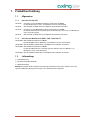
1. Product description
1.1. General
1.1.1. Modules for DVB-S/S2
SKT 40-00 Transmodulates four 8PSK/QPSK modulated transponders into COFDM.
Four full-fledged tuner inputs, four modulators, one output.
SKT 40-04 Like SKT 40-00, decoding of encoded programmes possible by using four CA modules
SKT 80-00 Transmodulates eight 8PSK/QPSK modulated transponders into COFDM.
The SKT 80-00 ist built in two units, each with four full-fledged tuner inputs,
four modulators and one output.
SKT 80-02 Like SKT 80-00, decoding of encoded programmes possible by using two CA modules.
1.1.2. Modules with multituner for DVB-S/S2, DVB-T/T2 or DVB-C
SKT 40-00M Transmodulates DVB-S/S2/T/T2/C/Cx into COFDM.
Four independent multituner inputs, four modulators, one output.
SKT 40-04M Like SKT 40-00M, decoding of encoded programs possible by using four CA modules
SKT 80-00M Transmodulates DVB-S/S2/T/T2/C/Cx into COFDM.
The SKT 80-00M ist built in two units, each with four independent multituner inputs,
four modulators and one output.
SKT 80-02M Like SKT 80-00M, decoding of encoded programs possible by using two CA modules.
1.2. Scope of delivery
1 × Headend module
1 × DC connection cable SKZ 40-00
1 × Quick start guide
Note. The power supply unit and the basic unit are not included in the scope of delivery of the modules. They
are available as an option. It is recommended to install the modules into a base unit.

Operation instructions | SKT 40-0x | SKT 80-0x | SKT 40-0xM | SKT 80-0xM
6 2017-01-26 | Technical changes, design modifications, errors and misprints are subject to change without prior notice.
1.3. Inputs/tuner
The quattro module includes four independent tuner and the octo module includes eight of them.
Headend modules with 8PSK/QPSK tuner can receive DVB-S/S2.
Headend modules with multituner can receive DVB-S/S2, DVB-T/T2 or DVB-C. For receiving DVB-T/T2 or
DVB-C the LNB power has to be switched off (see 3.3 on page 16) before connecting a antenna
cabel to one of the HF inputs!
Connection to the LNBs
On the SAT-IF input the headend modules have a remote supply voltage for the LNB and use DiSEqC 1.0
functionalities. Therefore, they can be connected directly to the LNB.
Multiswitches as input distributors
Optionally, you can also use multiswitches as input distributors. The advantage of this solution is that you can
set both the SAT IF level and the satellite via the user interface. Changes in the list of programmes can be
made using remote maintenance, so that it is not necessary to change or modify the input distribution on site.
Demodulation
The selection of the frequency and demodulation are both done in the tuner.
If needed, the programmes from the data flow of the demodulated transponder can be filtered (Remux mode).
Thanks to the Cross Multiplex Mode, FTA programmes (Free to Air) can be filtered from the data flow of
several tuners for a common output channel and be bundled again.
The prepared data flow is passed on to the modulators.

2017-01-26 | Technical changes, design modifications, errors and misprints are subject to change without prior notice. 7
1.4. Output/modulators
The output channels of the modulators are allways neighbour channels
The quattro module has four output modulators and one RF output.
The first modulator can be set to any output channel between S2 and CH 69. The other three modulators are
automatically set by incrementing the output channels in accordance with the chosen channel spacing.
For example: modulator 1 = Channel 21
modulators 2, 3 and 4 = Channels 22, 23 and 24
The octo module has eight output modulators. They are subdivided in two modulator groups of four
modulators each. The octo module has two RF outputs (each for one modulator group).
In both groups, the first modulator can be set to any output channel between S2 and CH 69. The next three
modulators of both modulator groups are automatically set by incrementing the output channels in accordance
with the chosen channel spacing.
For example: group A modulator 1 = Channel 21
modulators 2, 3 und 4 = Channels 22, 23 und 24.
group B modulator 1 = Channel 25
modulators 2, 3 und 4 = Channels 26, 27 und 28.
1.5. Graphical user interface
The settings of the modules can be changed via the user interface of the integrated web interface. To access
the user interface and thus configure the devices, you need a standard PC/laptop with a network interface and
the actual version of the installed web browser.

Operation instructions | SKT 40-0x | SKT 80-0x | SKT 40-0xM | SKT 80-0xM
8 2017-01-26 | Technical changes, design modifications, errors and misprints are subject to change without prior notice.
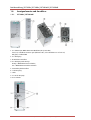
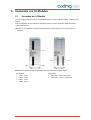
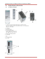
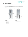
1.6. Display elements and connectors
1.6.1. SKT 40-0x | SKT 40-0xM
1. 4 × MPEG data stream modulator LED indicators (each with two LEDs)
Error (red) = Modulator stream too large (fill level >95%, see 3.2.2 on page 15)
OK (green) = Fill level O.K.
2. 4 × HF input
3. RJ-45 Ethernet port
4. 4 × HF input LED indicator:
Orange = MPEG data stream present,
Off = MPEG data stream not present
5. Equipotential bonding connection
6. 1 x HF output
7. Fan
8. 2 × DC input/output
9. 4 x CI slots

2017-01-26 | Technical changes, design modifications, errors and misprints are subject to change without prior notice. 9
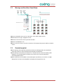
1.6.2. SKT 80-0x | SKT 80-0xM
1. 8 × MPEG data stream modulator LED indicators (each with two LEDs)
Error (red) = Modulator stream too large (fill level >95%, see 3.2.2 on page 15)
OK (green) = Fill level O.K.
2. 8 × HF input
3. 2 × RJ-45 Ethernet port
4. 8 × HF input LED indicator:
Orange = MPEG data stream present,
Off = MPEG data stream not present
5. Equipotential bonding connection
6. 2 × HF output
7. Fan
8. 2 × DC input/output
9. 2 x CI slots

Operation instructions | SKT 40-0x | SKT 80-0x | SKT 40-0xM | SKT 80-0xM
10 2017-01-26 | Technical changes, design modifications, errors and misprints are subject to change without prior notice.
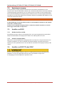
2. Mounting and Installation
The headend modules can be operated either in a headend base units or stand-alone with the external power
supply unit.
Installation must be performed by authorized and skilled electricians only.
Before inserting or changing a module, pull the mains plug of the headend base unit from the socket!
Observe the operation instructions of the corresponding headend base unit!
Observe the operation instructions of the corresponding power supply unit!
The antenna system must be installed and grounded according to the DIN EN 60728-11 standard.
2.1. Mounting and installation in a headend base unit

2017-01-26 | Technical changes, design modifications, errors and misprints are subject to change without prior notice. 11
2.2. Mounting and installation stand alone
Please note that the installation must be carried out on an even and vertical surface.
Any unevenness must be compensated.
Fix the module with 2 screws appropriated for the installation surface.
Install the module in compliance with the safety regulations defined by the EN 60728-11 standard.
For an operation without a basic unit, the outputs of several modules must be combined with a distributor.
2.3. Equipotential bonding
If the device is mounted in the headend base unit, the connection to the equipotential bonding has to be
done via the headend base unit. Observe the operation instructions of the headend base unit!
If the module is mounted external a headend base unit the module and the power supply unit must be
connected to the equipotential bonding according to EN 60728-11. Use the equipotential bonding
connection at the device.
To connect the outer conductor of the coaxial cable to the equipotential bonding, use e.g. QEW earthing
angles or CFA earth connection blocks at the inputs of the modules and output of the combiner.

Operation instructions | SKT 40-0x | SKT 80-0x | SKT 40-0xM | SKT 80-0xM
12 2017-01-26 | Technical changes, design modifications, errors and misprints are subject to change without prior notice.
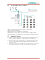
2.4. Power supply
The modules have two identical connecting sockets on the bottom for the power supply. Both are linked
together internally. One of both connecting sockets is used to get the operating voltage from the power supply
unit or from another module. The second one can be used to loop the operating voltage through to the next
module or to the output combiner of the base unit. With the DC patch cable (SKZ 40-00) included in the scope
of delivery, the modules can be connected together.
While looping the modules through, a maximum of 3 x SKT 80-0x or 4 x SKT 40-0x can be connected
together.
It is imperative to use a power supply unit with sufficient output power for your application!
Note that the power supply unit has to supply also the LNBs and the active combiner of the
headend base units if necessary!
2.5. Connection to DVB-S
2.5.1. Connection to the LNBs
On the SAT-IF input the headend modules have a remote supply voltage for the LNB and use DiSEqC 1.0
functionalities. Therefore, they can be connected directly to the LNB.
2.5.2. Multiswitches as input distributors
Optionally, you can also use multiswitches as input distributors. The advantage of this solution is that you can
set both the SAT IF level and the satellite via the user interface. Changes in the list of programmmes can be
made using remote maintenance, so that it is not necessary to change or modify the input distribution on site.
2.6. Connection to DVB-T/T2 or DVB-C
Before connecting the antenna cabel, the LNB power has to be switched off (see 3.3 on page 16). Active DVB-
T antennas have to be supplied by an external power supply.
The input level has to be 45-85 dBµV.

2017-01-26 | Technical changes, design modifications, errors and misprints are subject to change without prior notice. 13
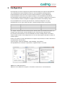
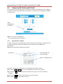
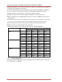
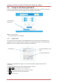
3. Configuration
The device is configured via the graphical user interface of the integrated web interface.
To access the user interface, you need a standard PC/laptop with a network interface and the actual version of
the installed web browser. To connect the network interface of the module to the computer, you need a
commercially available network cable.
The HTTP protocol is used for communication allowing a worldwide remote maintenance of the systems at
various locations via the Internet. Access protection is implemented by means of the password prompt.
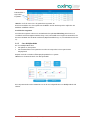
The SKT 80-00 features two separate units that each have four tuners, four modulators and one HF output.
Every unit has its own web interface and its own static IP address. The following values are preset ex factory:
SKT 40
-
0x/M
:
IP address:
192.
168.0.145
SKT 80
-
0x/M
:
IP address, left side:
192.168.0.145
IP address, right side:
192.168.0.146
Subnet mask:
255.255.255.0.
The computer and the module must be in the same subnetwork. The network part of the IP address of the
computer must be set to 192.168.0. and the subnet mask must be set to 255.255.255.0.
The host part of the network address is required for the identification of the devices and can be assigned in the
subnetwork only once. You can allocate to the computer any not allocated host address between 0 and 255.
Change the IP address and the subnet mask of your computer accordingly.
(e.g.: IP address:192.168.0.11 and subnet mask: 255.255.255.0)
Control panel > Network connections > LAN connection >Properties > Internet protocol version 4 TCP/IPv4 >
Properties > Use the following IP address:
Click OK to save.
Start your web browser and enter the IP address of the module: e.g.: 192.168.0.145.

Operation instructions | SKT 40-0x | SKT 80-0x | SKT 40-0xM | SKT 80-0xM
14 2017-01-26 | Technical changes, design modifications, errors and misprints are subject to change without prior notice.
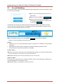
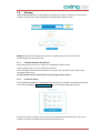
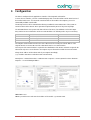
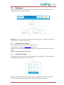
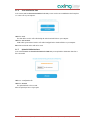
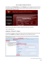
3.1. Login and logout
The web-based user interface is protected against unauthorized access. When accessing the user interface, the
first thing is the password request.
Enter the default password: Ramsen8262
Click the button ENTER PASSWORD .
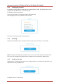
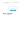
If you are not automatically forwarded to the start
page, click then the button OPEN PAGE .
In the header, the user can choose the language of the user interface. The possibilities are German (DE) and
English (EN). The standard language of the user interface is English. The chosen language applies until the end
of the session.
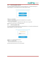
To log out, click the button LOG OUT in the header of the website. In the browser, the message "Goodbye!“
appears.
Notes:
∂ If the browser is closed while you are still logged in, an automatic logout occurs 2.5 minutes later.
∂ If the browser window stays open, there is no automatic logout. It allows monitoring the installation via
the web browser.
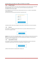
Changing the password:
Please change the password immediately after the first commissioning and choose a sufficiently safe
password. Keep this password at a safe place.
Menu item: Maintenance > Set new password (see 3.6 on page 25)
Changing the IP address:
If needed, the modules can be integrated in a network. For this application, some changes must be applied to
the network configuration.
Menu item Maintenance > System Options (see 3.6 on page 25)

2017-01-26 | Technical changes, design modifications, errors and misprints are subject to change without prior notice. 15
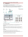
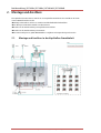
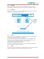
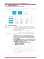
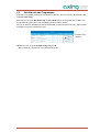
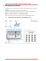
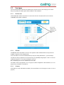
3.2. Front page
The relevant information required for the function of the system are shown on the front page. The decisive
thing is the quality of the input signals and the utilization of the modulators.
3.2.1. Bit error rate
The bit error rate of all four SAT IF tuners is shown on the left side. The amount of bit errors for the last
1,000,000 transferred bits is calculated.
3.2.2. Fill level
The fill level of all four modulators is shown on the right side. 100% modulator fill level correspond to the
maximal net data rate of the output channel.
If the current fill level exceeds the maximal fill level, it may cause image disturbances, e.g. mosaic images.
The data rates of the programmes are not constant. They are dynamically changed by the sender. To ensure an
undisturbed reception, a reserve must absolutely be observed.
We recommend you to set the maximal fill level to 90%.
The number of choosen programmes (see 3.4 on page 18) and the configuration of the modulators (see 3.5 on
page 22) have an influence to the fill level.
3.2.3. CI menus
If CA moduls are used in SKT 40-04 or SKT 40-02, the CI menu buttons on the front page are active (see 4.2 on
page 30).
Here you can
navigate to the
Initialization and
Maintenance
pages.

Operation instructions | SKT 40-0x | SKT 80-0x | SKT 40-0xM | SKT 80-0xM
16 2017-01-26 | Technical changes, design modifications, errors and misprints are subject to change without prior notice.
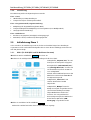
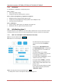
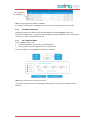
3.2.4. Initialization
The initialization is subdivided in 3 configuration phases.
Phase 1: Tuners.
∂ LNB settings, DiSEqC settings,
∂ Transponder frequency and transponder search run.
Phase 2: Chosse of programmes, programme arrangement.
∂ Multiplexing after programme filtering (Remux mode)
∂ Transponder crossing multiplexing of FTA programmes (Cross-Multiplex mode)
∂ LCN (Logical Channel Numbering)
Phase 3: Modulators.
∂ Channel spacing, output channel, fine calibration and output level.
∂ Modulation, code rate, guard interval, transmission mode.
3.3. Initialization phase 1
During the first phase of the initialization, the tuner settings required for the scan are made and the station
scanning is carried out. The four tuners work independently from each other and after the same principle.
3.3.1. DVB-S (für 8PSK/QPSK- und für Multituner-Kassetten)
Choose the tuner with the button Tuner 1…4 .
Configure the needed settings for all tuners.
The SAT IF frequency of the transponder is
entered in the input field "Frequency
(MHz)".
The input fields "LOF Low Band (MHz)"
and "LOF High Band (MHz)" correspond to
the oscillator frequencies of the LNB in low
and high band.
The default settings of the oscillator
frequencies are 9,750 MHz for the low band
and 10,600 MHz for the high band.
In the optional field "Polarisation", you can
switch from horizontal to vertical.
In the optional field "DiSEqC", the DiSEqC
command signals can be turned off or set to
switch a DiSEqC-enabled multi switch on the
positions 1 to 4.
If required, the operating voltage for the LNB
can be switched off via the optional field
"LNB power supply".
After all settings have been made, click the button SCAN .
A rotating circle is shown on the right side during the scanning process.

2017-01-26 | Technical changes, design modifications, errors and misprints are subject to change without prior notice. 17
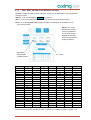
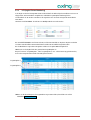
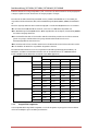
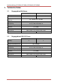
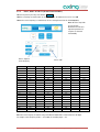
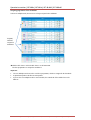
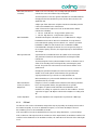
3.3.2. DVB-C, DVB-T or DVB-T2 (for multi tuner modules)
Select any tuner by the help of the buttons Tuner 1…4 .
Before connecting an antenna cable to an according tuner, the LNB Power has to be set to off
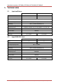
Enter the center frequency (see table below) for the receiving channel into the field FREQ (MHz).
Note: All other entry fields
are not relevant.
Modulation and all other
important parameter for
reception are detected
automatically.
Channel
Input
Channel
Input
Channel
Input
Channel
Input
S 21
306
21
474
41
634
61
794
S 22
314
22
482
42
642
62
802
S 23
322
23
490
43
650
63
810
S 24
330
24
498
44
658
64
818
S 25
338
25
506
45
666
65
826
S 26
346
26
514
46
674
66
834
S 27
354
27
522
47
682
67
842
S 28
362
28
530
48
690
68
850
S 29
370
29
538
49
698
69
858
S 30
378
30
546
50
706
S 31
386
31
554
51
714
S 32
394
32
562
52
722
S 33
402
33
570
53
730
S 34
410
34
578
54
738
S 35
418
35
586
55
746
S 36
426
36
594
56
754
S 37
434
37
602
57
762
S 38
442
38
610
58
770
S 39
450
39
618
59
778
S 40
458
40
626
60
786
S 41
466
Note: The center frequeny of channels using a bandwith of 7MHz will be rounded down to 3 full digits.
For example: center frequency of CH 5 = 177,5 MHz, the according input = 177.
Enter 3- digits for
center frequency
Choose “Off”

Operation instructions | SKT 40-0x | SKT 80-0x | SKT 40-0xM | SKT 80-0xM
18 2017-01-26 | Technical changes, design modifications, errors and misprints are subject to change without prior notice.
3.3.3. Bit error rate
The BIT ERROR RATE is shown in the middle area. The amount of bit errors for the last 1,000,000 transferred
bits is calculated.
3.3.4. Found programmes
After a successful station scanning, the radio and TV stations are shown in the area "FOUND PROGRAMS".
The table contains information about programme type and encoding.
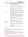
3.4. Initialization phase 2
In the initialization phase 2, the found programmes are subdivided by tuner. The programme name, the
programme type and information about the encryption are shown.
After the station scanning in initialization phase 1 no assignment to a output modulator has been done. The
output channels of the modulators still have no programme.
All lines of the programme table have in the "Modulator" column four colored buttons M1 to M4. The buttons
correspond to the four modulators. The allocation of the buttons is given in the COLOR CODES legend.
You can assign programmes to modulators in remux mode or in cross multiplex mode.
Important:
With each programme you asign to an modulator, the data rate rises.
The performed modifications are only taken over by the system when you click the button SAVE CHANGES .
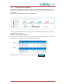
3.4.1. Remux mode
If the transport stream IDs of the four modulators and the network ID are set on "auto", the module works in
the Remux mode. In this mode, the IDs from the set transponder and from the satellite are used and forwarded
to the modulators with virtually no changes.
Assigning programmes
Every tuner is assigned to a modulator. The programmes of the tuner can only be assigned to the associated
modulator.
Click onto the modulator button, the programme is assigned to the modulator.
For example click in table TUNER 1 on the button M1.
The programme is assigned to modulator 1. The button of the modulator is highlighted in color.

2017-01-26 | Technical changes, design modifications, errors and misprints are subject to change without prior notice. 19
Chose the programmes for TUNER 1 to TUNER 4.
A new click on a button allow the assignment to be canceled. The modulator buttons fades then again.
3.4.2. Scrambled programmes
Scrambled programmes are indicated by the abbreviation CA in the column Encryption. They can be
forwarded in encrypted form, or be decrypted in the SKT 40-04 or SKT 80-02 module by means of an integrated
CA module (see 4. Use of CA modules at page 29).
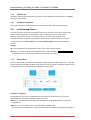
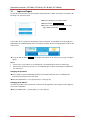
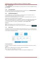
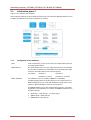
3.4.3. Cross Multiplex Mode
The cross multiplex mode is used:
∂ To split the programmes of a transonder to several modulators.
∂ To merge pogams of several transponders into one output channel.
Transmission capacities in the distribution networks can be optimized.
Change the network ID to a value greater than zero.
The IDs of the transport streams are automatically incremented by one to four, the cross multiplex mode is
activated.
Choosen programs
for modulator 1
Page is loading ...
Page is loading ...
Page is loading ...
Page is loading ...
Page is loading ...
Page is loading ...
Page is loading ...
Page is loading ...
Page is loading ...
Page is loading ...
Page is loading ...
Page is loading ...
Page is loading ...
Page is loading ...
Page is loading ...
-
 1
1
-
 2
2
-
 3
3
-
 4
4
-
 5
5
-
 6
6
-
 7
7
-
 8
8
-
 9
9
-
 10
10
-
 11
11
-
 12
12
-
 13
13
-
 14
14
-
 15
15
-
 16
16
-
 17
17
-
 18
18
-
 19
19
-
 20
20
-
 21
21
-
 22
22
-
 23
23
-
 24
24
-
 25
25
-
 26
26
-
 27
27
-
 28
28
-
 29
29
-
 30
30
-
 31
31
-
 32
32
-
 33
33
-
 34
34
-
 35
35
-
 36
36
-
 37
37
-
 38
38
-
 39
39
-
 40
40
-
 41
41
-
 42
42
-
 43
43
-
 44
44
-
 45
45
-
 46
46
-
 47
47
-
 48
48
-
 49
49
-
 50
50
-
 51
51
-
 52
52
-
 53
53
-
 54
54
-
 55
55
-
 56
56
-
 57
57
-
 58
58
-
 59
59
-
 60
60
-
 61
61
-
 62
62
-
 63
63
-
 64
64
-
 65
65
-
 66
66
-
 67
67
-
 68
68
-
 69
69


Axing SKT 40-20M Operation Instructions Manual
- Category
- Modulator
- Type
- Operation Instructions Manual
Ask a question and I''ll find the answer in the document
Finding information in a document is now easier with AI
in other languages
- Deutsch: Axing SKT 40-20M
Related papers
-
Axing SKT 40-20M Operation Instructions Manual
-
-
-
-
-
-
-
-
Axing basic-line Series Operation Instructions
-
Other documents
-
 TBS MOI+ User manual
-
POLYTRON HDI 32 C IP modulator into 32xDVB-C Operating instructions
-
-
-
-
-
-
-
PEAK NET-TV Operating Instructions Manual
-
 ANTIFERENCE Conexer DMHD01 User manual

