Page is loading ...

VCC-6574PC
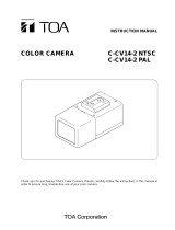
NAMES AND FUNCTIONS OF PARTS
INSTRUCTION MANUAL
COLOR CCD camera
About this manual
Before installing and using the camera, please read this manual
carefully. Be sure to keep it handy for later reference.
Dimensions: mm
Lens cap
Protects the lens from damage.
FLANGE BACK ADJ. (Flange-back adjustment screw)
FLANGE BACK LOCK (Flange-back lock screw)
Locking screw for the flange-back adjustment screw.
Camera attachment bracket
The bracket can be secured at the top or bottom of camera.
When securing the bracket, use the long screws and use the short screws
on the opposite side to seal the openings.
When installing the camera support, select a location that can support the
total weight of the camera and accessories.
Depending on the conditions of use, installation and
environment, please be sure to make the appropriate settings
and adjustments. If you need help with installation and/or
settings, please consult your dealer.
12.6
22.4
11
0.5
109
100
1/4”–20 UNC
56
45
28
long screws
short screws
Camera adjustment/setting panel
Contains camera adjustment dials and setting switches.
LENS (Lens iris output terminal)
Used to connect the lens plug when the lens is attached.
VIDEO OUT (Video output terminal: BNC connector)
Connects to the video input terminal on the peripheral equipment.
LINE PHASE (Line phase adjustment dial)
When using two cameras or more, the image on the monitor may roll
vertically when switching sources. This rolling can be minimized by turning
this dial.
POWER (Power indicator)
Lights when the camera power is ON.
GND, AC24V (Ground terminal, AC 24 V input terminal)
Q
Attaching a lens
The 1/3-inch DC type, CS mount auto-iris lens (sold separately) is
recommended.
1 Remove the lens cap.
2 Attach the lens.
Turn the lens slowly to attach it to the
camera.
3 Connect the lens plug to the LENS
terminal.
When using different shape or
specification of the plug, connect the
supplied lens iris plug.
When attaching the lens, use a lens with a mount screw
(L) that is less than 5 mm in length. If a lens that exceeds
this size is used, the camera may be damaged and you
may not be able to attach it correctly.
When attaching a C mount lens, attach the lens to the
camera after inserting the C mount ring (sold
separately).
Q
When using different shape of the lens plug
Rewire the lens cable in the supplied lens iris plug.
1 Prepare the lens cable.
Cut the cable at the plug, then
remove approx. 8 mm of the cable
sheath and strip about 2 mm from
each wire.
2 Install the lens iris plug.
Solder the cable to the pins following
the correct pin layout, then close the
plug cover.
1AC6P1P2802--
L53X4/C (0304TR-TT)
1
2
3
DC type lenses VIDEO type lenses
Brake coil (-) DC +12 V (50 mA max.)
Brake coil (+) Not used
Drive coil (+) Video output (1.0 V(p-p), high impedance)
Drive coil (-) Ground (for video signal and DC power)
L
8 mm
2 m
m
SANYO Electric Co., Ltd.
J
In case of problem
Do not use the camera if smoke or strange odors come from the
unit, or if it seems not to function correctly. Disconnect the power
cord immediately, and consult your dealer or a Sanyo Authorized
Service Center.
J
Do not open or modify
Do not open the cabinet, as it may be dangerous and cause
damage to the unit. For internal settings and repairs, consult your
dealer or a Sanyo Authorized Service Center.
J
Do not put objects inside the unit
Make sure that no metal objects or flammable substances get
inside the camera. If used with a foreign object inside, it could
cause fire, short-circuits or damage. If water or liquid gets inside the
camera, disconnect the power cord immediately, and consult your
dealer or a Sanyo Authorized Service Center. Be careful to protect
the camera from rain, sea water, etc.
J
Be careful when handling the unit
To prevent damage, do not drop the camera or subject it to strong
shock or vibration.
J
Install away from electric or magnetic fields
If installed close to a TV, radio transmitter, magnet, electric motor,
transformer, or audio speakers, the magnetic field they generate
will distort the image.
J
Protect from humidity and dust
To prevent damage to the camera, do not install it where there is
greasy smoke or steam, where humidity may get too high, or where
there is a lot of dust.
J
Protect from high temperatures
Do not install close to stoves, or other heat generating devices,
such as spotlights, or where it could be subject to direct sunlight, as
that could cause deformation, discoloration or other damage.
Be careful when installing close to the ceiling, in a kitchen or boiler
room, as the temperature may rise to high levels. Install where the
temperature range will stay between -10°C (14°F) and 50°C
(122°F). (no condensation)
J
Cleaning
Dirt can be removed from the cabinet by wiping it with a soft cloth.
To remove stains, use a soft cloth moistened with a soft
detergent solution and wrung dry, then dry by wiping with a soft
dry cloth.
Do not use benzine, thinner or other chemical products on the
cabinet, as they may cause deformation and paint peeling.
Before using a chemical cloth, make sure to read all
accompanying instructions. Make sure that no plastic or rubber
material comes in contact with the cabinet for extended periods,
as that may cause damage or paint peeling.
PRECAUTIONS
Before sending the camera out for repair, check the items below.
If the problem persists after checking these items, consult your
dealer or a Sanyo Authorized Service Center.
J
If no image appears
Are the power and voltage normal?
Are all the signal connecting cables correctly connected?
Is there adequate illumination?
Has the lens cap been removed?
Is the lens type (DC or VIDEO) correctly selected?
Depending on the type of lens, the A. I. LENS switch must be set
accordingly.
Has the iris of the lens inside the camera been adjusted correctly
(with the lens iris dial)?
J
If the image is unclear
Is the monitor adjusted correctly?
Is the flange-back position correctly set?
Is the lens in focus?
Is the lens dirty?
Dirt or fingerprints on the lens can adversely affect the image.
Gently wipe any dirt or fingerprints off the lens with a soft cloth or
lens cleaning paper and cleaning fluid (commercially available).
The camera is a precision instrument. Handle it carefully and
always follow the safety precautions. If the camera requires service,
never try to repair it yourself or open the casing.
For servicing, maintenance, or repairs, consult your dealer or a
Sanyo Authorized Service Center.
Features and specifications are subject to change without prior notice or
obligations.
TROUBLESHOOTING
SERVICE
SPECIFICATIONS
Scanning system : PAL standard (625 TV lines, 25 frames/s)
Interlace : PLL 2:1 interlace
Image device : 1/3 inch solid state image device CCD
Effective picture
elements
: 752 (H) x 582 (V)
Synchronizing system : Internal sync/Line lock (manually switchable)
Resolution : 520 TV lines horizontally, 400 TV lines vertically
Video output level : 1.0 V(p-p)/75 Ω, composite
Video S/N ratio : More than 48 dB
Aperture : Sharp/Normal (manually switchable)
Minimum required
illumination
(incandescent lighting)
: Approx. 1.0 lx (F 1.2 lens)
Backlight
compensation
: Selectable by switches:
Multi-spot metering system/Center-weighted
metering system/OFF
Iris function : Electronic-iris/Auto-iris (manually switchable)
Electronic shutter : 8 speeds, selectable by switches:
1/50 - 1/10000 s
White balance : Auto/Manual switching
Lens mount : CS mount
Environmental
conditions
: Temperature: -10°C ~ +50°C
Humidity: less than 90%RH (no condensation)
Power supply : AC 24 V, 50 Hz
Power consumption : Approx. 3.5 W (with auto-iris lens)
Approx. 2.6 W (with manual or fixed iris lens)
Weight : Approx. 310 g (without lens)
Accessories : Lens iris plug (with the plug cover)

CONNECTIONS
Q
What you need
Peripheral equipment (such as monitor, digital video recorder or time-
lapse VCR)
Cables for connecting peripheral equipment and camera (coaxial cables,
connecting plug)
Power adapter (AC 24 V)
Q
Supported coaxial cables
You can use any of the following coaxial cables:
RG-59U (3C-2V) Length: 250 m max.
RG-6U (5C-2V) Length: 500 m max.
RG-11U (7C-2V) Length: 600 m max.
When using an RG-59U (3C-2V) cable, do not use it on piping or air
wiring.
Select the cable according to the distance between the devices you wish
to connect.
If you use a cable other than the types above, the image or sync signal
will be attenuated and will not be transmitted correctly.
Q
Making connections
1 Connect the camera and peripheral equipment with cables.
2 Connect the power cable.
Connect 3 wire grounded cable (# 18 AWG+).
To prevent a fire hazard use any UL listed wire rated VW-1 for the
AC 24 V input terminal.
3 Insert the plug of this power cord into a wall outlet.
The POWER indicator will light.
FLANGE BACK ADJUSTMENT
If the pick-up surface is not correctly positioned with relation to the lens
focal point, the picture will be out of focus (in particular when using auto-iris
power zoom lenses, sold separately). If that is the case, adjust the FLANGE
BACK position as described below.
1 Using a + screwdriver, loosen the
FLANGE BACK LOCK screw (M2:+).
2 Set the zoom lens to the maximum
telephoto position, and set the focus
using the focus ring on the lens.
3 Set the zoom lens to the maximum
wide angle position, and set the focus
using the FLANGE BACK ADJ. screw.
Repeat steps 2 and 3, until the image
stays in focus when changing from a
telephoto shot to a wide angle shot.
4 When the setting is complete, tighten
the FLANGE BACK LOCK screw.
CONNECTIONS AND INSTALLATION
POWER
VIDEO OUT
AC 24V
Push to insert
the cable.
Monitor
Degital video recorder
or time-lapse VCR
1
2
3
Video signal
: VIDEO IN
: VIDEO OUT
AC 24V
CONNECTIONS
ADJ.
FLANGE BACK
LOCK
3
2, 3
1, 4
The camera comes pre-adjusted and ready to install at time of factory
shipment, but you may want to make adjustments or settings to adapt to the
operating conditions or installation environment.
If you have trouble adjusting the camera, consult your dealer or a Sanyo
Authorized Service Center.
Q
Iris setting (IRIS) and electronic shutter speed
setting (ES)
Select iris setting when using either lens below.
Electronic shutter speed settings
(Unit: seconds)
Using the high speed electronic shutter indoors with low lighting, will give
darker pictures. In such a case, add some lights to make sure the lighting
is sufficient.
If the lighting is very bright, pay attention to the light angle in order to
avoid or minimize the smear phenomenon effect.
If using a manual or fixed iris lens under fluorescent light, the image may
flicker.
Q
Outline compensation (APER:Aperture)
Q
Backlight compensation (BLC)
You can set the metering area ( ), to have the lens iris adjust
automatically to make the image easy to see when the object is backlit.
(Active when using an auto-iris lens.)
Q
Color compensation (WB:White balance)
Q
Sync setting (SYNC)
Line phase adjustment dial
When sync setting is set to Line-Lock (LL) and two or more cameras are
connected, the image displayed on the monitor may roll vertically.
If using this product as the second or
subsequent camera;
Adjust the roll by turning the LINE PHASE dial.
If using this product as the first camera;
Adjust the roll by turning the line phase
adjustment dial on the second and subsequent
cameras.
Q
Lens setting (A.I. LENS)
Set this as appropriate for the type of lens you are using.
When using a VIDEO type auto-iris lens, turn the ALC (light control) dial on
the lens barrel fully to AV (average).
Q
Lens iris dial
If the entire image is too dark or too bright when using an auto-iris lens (AI),
adjust this dial ( ).
ADJUSTMENT AND SETTINGS
AI When using an auto-iris lens, set the IRIS switch 4 and
select electronic shutter speed.
EI (for indoor use) When using a manual or fixed iris lens, set the IRIS
switch 4.
* Set the lens aperture to the shortest F stop.
1/50 1/120 1/250 1/500 1/1000 1/2000 1/4000 1/10000
SHRP Emphasizes object outlines.
NORM When object outlines appear too strong.
EI LLSHRP CENT ON MANU
IRIS SYNCAPER BLC WBES
123
NC
AI INTNORM MULT OFF ATWMSB LSB
DC
VIDEO
A. I.
LENS
VR301
VR303
BR
VR302
6785
ON
1093421
2 4 5 63
7
This switch
is not used.
The illustration shows the factory default settings for the switches in
the camera adjustment/setting panel.
The sticker on the inside of cover.
1
4
4
123 123 123 123 123 123 123 123
2
When
applying
backlight
compensation
to the whole of
the screen.
Multi-spot metering
The screen is divided into 64 areas, and
each area is metered and backlight-
compensated.
If the background of the object is
extremely dark, the center of the object
may be too bright. In this case, set
center-weighted metering mode.
When
applying
backlight
compensation
to only the
central portion
of the screen.
Center-weighted metering
Only the central portion of the screen is
metered and backlight-compensated.
MANU Lets you fine-tune the white balance manually.
• R (Red) dial : Turn clockwise to augment screen red.
• B (Blue) dial : Turn clockwise to augment screen blue.
ATW Compensation is performed automatically.
LL Line-Lock: Synchronizes the unit with power frequency.
• If the image on the monitor rolls vertically when two or more cameras
are connected, refer to “Line phase adjustment dial” below.
INT Internal Sync
VIDEO VIDEO type auto-iris lens (lens with built-in amp circuits)
DC DC type auto-iris lens (lens without built-in amp circuits,
powered by DC power only)
Counterclockwise Closes the lens iris, making the entire image darker.
Clockwise Opens the lens iris, making the entire image brighter.
3
67
67
4
5
R
5
B
R
B
5
5
LINE
PHASE
6
7
7
/