Page is loading ...

2
5
5
00.0‐051116
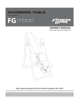
In
v
v
er
s
s
io
n
Ta
b
b
le


SERVICE---------------------------------------------------------------------- 2
LABLE PLACEMENT------------------------------------------------------- 3
IMPORTANT SAFETY INSTRUCTIONS------------------------------- 4
OVERVIEW DRAWING---------------------------------------------------- 7
PARTS LIST------------------------------------------------------------------- 8
HARDWARE PACK---------------------------------------------------------- 9
ASSEMBLY-------------------------------------------------------------------- 10
SAFETY OPERATING INSTRUCTIONS------------------------------ 22
OPERATION AND ADJUSTMENTS------------------------------------ 23
STORAGE--------------------------------------------------------------------- 28
WARRANTY------------------------------------------------------------------- 29
PARTS REQUEST FORM------------------------------------------------- 30
TABLEOFCONTENTS
1

IMPORTANT: FOR NORTH AMERICA ONLY
For damage or defective product, questions, replacement parts
or any other service support, please contact our customer
service department (8:00 AM - 5:00 PM Pacific Standard Time,
Daily) by below methods:
For Best Service Email:
Service@paradigmhw.com
Response time may vary.
Website:
www.paradigmhw.com
Toll-Free:
1-844-641-7920
Please have the following information ready when requesting for service:
Your name
Phone number
Model number
Serial number
Part number
Proof of Purchase
For damaged or defective product please contact our customer
service before returning to the store.
* Emailing us with the information above will be the best method
to receive a response during peak business hours.
Paradigm Health & Wellness, Inc.
1189 Jellick Ave.
City of Industry, CA 91748, USA
SERVICE
2

Heel Bracket
must be
secured in
slot before
use.
Support de talon doit
être xé dans le fente,
avant utilization.
El soporte de talón
debe jarse en la
ranura antes de usar.
LABELPLACEMENT
3

This inversion table was designed and built for optimal safety. However, certain precautions
apply whenever you operate this exercise equipment. Be sure to read the entire manual
before assembling and operating this equipment. When using this equipment, basic
precautions should always be followed, including the following:
WARNING - To reduce the risk of injury:
1. Consult your physician or other health care professionals before using the inversion
table.
2. Use this appliance only for its intended use as described in this manual.
3. Do not use attachments not recommended by the manufacturer.
4. Never operate this Equipment if it is damaged, if it is not working properly, if it has been
dropped or damaged. If a problem is encountered contact Customer Service.
5. Do not use outdoors.
6. Do not exceed the maximum rated weight (load) and maximum rated user height.
7. The Equipment weighs more than 44lbs / 20kgs and should be assembled and moved by
two or more people.
8. For Household Use Only.
9. Always wear proper exercise apparel when using the equipment.
10. If at any time you feel faint, light-headed or dizziness while operating the equipment, stop
exercise immediately. You should also stop exercising if you are experiencing pain or any
discomfort.
11. Only one person should use the equipment at a time.
12. Make sure your equipment is correctly assembled before you use it. Be sure all the
screws, nuts, and bolts are tightened prior to use.
13. Pay attention to your body: Come up slowly after being inverted, dizziness after a session
means you came up too fast.
14. Wait a while after eating before using the inversion table. If you get nauseous, come up
as soon as you feel queasy.
15. Always use this equipment on a clear and level surface. Do not use near water.
16. Close supervision is necessary when this inversion table is used by elderly or disabled
persons.
17. Close supervision is necessary when this inversion table is used near children, or near
pets
18. Never drop on insert any object into any opening.
19.
WARNING: ALWAYS HOLD ON TO THE SAFETY HANDLES AND GO BACK
SLOWLY WHEN INVERTING. FAILURE TO COMPLY COULD RESULT IN SERIOUS
BODLIY INJURY.
20.
WARNING: To reduce the risk of personal injury, read and understand all the
instructions before using the inversion table.
21.
WARNING: Risk of personal injury – Do not allow children to use this machine.
IMPORTANTSAFETYINSTRUCTIONS
4

22. WARNING: Risk of personal injury – Keep children away from the machine while
in use.
23.
WARNING: Risk of personal injury – Do not grab the brake handle for getting up
from an inverted position, use the two handle bars instead.
24.
WARNING: Risk of personal injury - Keep body parts, hair, loose clothing and
jewelry clear of all moving parts.
NOTE: Maximum user weight for this product is 300 lbs (136 kgs.)
Maximum Rated Height for this product is 6’6”/198cm.
WARNING: Before using this equipment you should consult with your personal
physician to see if inversion equipment is appropriate for you.
Do not use this
equipment without your physician's approval.
Do not use this equipment if you have any of the following
conditions or ailments:
Extreme obesity
Glaucoma, retinal detachment or conjunctivitis
Pregnancy
Spinal injury, Cerebral Sclerosis, or acutely swollen joints
Middle ear infection
High blood pressure, Hypertension, Recent stroke or Transient Ischemic attack
Heart or circulatory disorders for which you are being treated.
Hiatus hernia or Ventral hernia
Bone weaknesses including Osteoporosis, Unhealed fractures, modularly pins or
surgically implanted orthopedic supports.
Use of anti-coagulants, which includes Aspirin in high doses.
IMPORTANTSAFETYINSTRUCTIONS
5

IMP
O
O
RTANT
S
S
AFETYI
N
6
N
STRUCTIONS

OVERVIEWDRAWING
7

No. Description Qty No. Description Qty
001
Front U-Frame
1 028
Upper Bed Frame End Cap
1
002
Rear U-Frame
1 029
Handlebar
2
003
Adjustable Boom
1 030
Knob
1
004
Bed Frame
1
031
Rear Heel Holder
4
005
Pivot Arm
2 032
Nylon Strap
1
006
Adjustable instep Frame
1 033
Loop Strap
1
007
Steel Heel Holder Bracket
4 034
Strap Lock
1
008
Folding Arm
2 035
Bed
1
009
Rod
1 036
Foam Grip
2
010
Hex Head Bolt
4
037
Right Protective Cover
1
011
Hex Head Bolt
2 038
Left Protective Cover
1
012
Phillips Screw
4 039
Foot Bar
1
013
Washer
16 040
Hex Head Bolt
2
014
Round Plate
1 041
Square End Cap
2
015
Lock Nut
8 042
Spring Latch
1
016
Lock Nut
6 043
Hex Head Bolt
2
017
T-shape Spring Knob
1 044
Nut Cap
2
018
Round Spring Knob
1 045
Plastic Bushing
1
019
Safety Hook
2 046
Rectangle End Cap
5
020
Rubber Pad
1 047
Pivot Arm Ring
2
021
Oval End Cap
2 048
Screw
4
022
Foot bar End Cap
2
049
Right Foot Cap
2
023
Spring
1 050
Left Foot Cap
2
024
Adjustable instep Frame Square
End Cap 1
051
Screw
4
025
Rod Round End Cap
4 052
Washer
8
026
Lower Bed Frame Bushing
2 053
Lumbar Pad
1
027
Washer
13 054
Bolt 5
PARTSLIST
8

HARDWAREPACK
9

This product weighs more than 44lbs/20kgs and should
be assembled and moved by two or more people.
Step 1:
Rest the frame on its side and pull the Front and Rear U-Frames (1, 2) as far
apart from each other
as possible. Then push down on the middle of the two
Folding Arms (8) until
they are fully locked down.
Attach each of the Left & Right Foot Caps (49, 50) to the Front & Rear
U-Frame (1, 2)
with one Screw (48), one Screw (51), and two Washers (52).
Tighten
the
screws with the Phillips Screwdriver provided.
Tool:
Phillips Screwdriver 1PC
ASSEMBLY
10
Hardware:
(48) Screw
4PCS
(52) Washer
8 PCS
(51) Screw
4PCS

Step 2:
Install two Nut Caps (44) onto the Lock Nuts (15). Slide the Right/Left
Protective
Covers (37, 38) on to each side of the base as shown, and pull
down on the
Right/Left Protective Covers (37, 38) until the bottom of the
covers are slightly
lower than the Folding Arms (8). Use the Velcro straps on
the bottom of the
Right/Left Protective Covers (37, 38) to secure the covers to
the Folding Arms
(8). When the covers are assembled correctly, the Folding
Arms (8) should be
fully covered by the Right/Left Protective Covers (37, 38)
ASSEMBLY
11
Hardware:
(44) Nut Cap
2PCS
8
8

Step 3:
Slide the bottom of the Pivot Arms (5) into the brackets of the Bed Frame (4) that are
located at each side
of the Bed (35). Align the desired hole on the Pivot Arm (5) with the
peg on the
bracket of the Bed Frame (4). Insert the peg into the hole to lock the Pivot
Arms (5) in place.
NOTE: It is
recommended that you use the bottom hole on the Pivot Arms (5) until you
become more familiar with the equipment.
Step 4:
Install the Pivot Arm Rings (47) onto the Pivot Arms (5). Mount the Bed Frame (4) to
the Rear U-Frame (2) by inserting the ends of the Pivot Arms (5) into the
channels on the
plates. The slotted portion of the rollers on the end of the Pivot
Arms (5) should be
inserted into the channels on the plates.
ASSEMBLY
12
Hardware:
(47) Pivot Arm Ring
2PCS
4
4
4

Step 5:
Slide the Rod (9) through the large round hole on the side of the Adjustable
Boom
(3), and secure the Rod (9) on the Adjustable Boom (3) with one Hex
Head
Bolt (11), one Lock Nut (16), and two Washers (27). Tighten bolt and Lock
Nut
with the two Multi Hex Tools provided.
Wrap both the Rear Heel Holder (31) with a Steel Heel Holder Bracket (7).
Slide them onto the ends of the Rod (9) until the lock teeth are wedged into the
slot on the Rod (9).
Note: Make sure the lock teeth are wedged into the slots in the Rod (9) to lock
the Steel Heel Holder Brackets (7) and Rear Heel Holders (31) in place before
use.
ASSEMBLY
13
Hardware:
(11) Hex Head Bolt
1PC
(16) Lock Nut
1PC
(27) Washer
2PCS
Tool:
Multi Hex Tool 2PCS

Step 6:
Slide the Foot Bar (39) into the bottom of the Adjustable Boom (3) and align two of the holes
on the Foot Bar (39) with the two holes on the Adjustable Boom (3). Secure the Foot Bar (39)
in place using two Hex Head Bolts (40), two Lock Nuts (15) and four Washers (13). Tighten
the Bolts and the Lock Nuts with the 6mm Allen Wrench and the Hex Wrench provided
Note: The extra holes on the Foot Bar (39) are for adjusting the distance between the Rear
Heel Holders (31) and the Foot Bar (39). The best set of holes to use will vary depending on
the users’ personal comfort. Once the inversion table is completely assembled, try
different positions for the Foot Bar (39) if the first set of holes you try is not comfortable.
Always thoroughly tighten the hardware before testing different positions for the Foot
Bar (39).
ASSEMBLY
14
Tool:
Multi Hex Tool 1PC
6mm Allen Wrench 1PC
Hardware:
(13) Washer
4PCS
(15) Lock Nut
2PCS
(40) Hex Head Bolt
2PCS

Step 7:
Wrap Both the Rear Heel Holders (31) with a Steel Heel Holder Bracket (7).
Slide them onto the ends of the Adjustable Instep Frame (6) until the lock teeth
are wedged into the slot on the Adjustable Instep Frame (6).
Note: Make sure the lock teeth are wedged into the slots on the Adjustable
Instep Frame (6) as shown in Fig. A and B before using the inversion table.
ASSEMBLY
15

Step 8:
Remove the Square End Cap (41) from the rear of the Adjustable Boom (3).
Pull up on the T-Shaped Knob (17) and carefully insert the Spring (23) and the
Adjustable Instep Frame (6) all the way into the empty square tube on the
Adjustable Boom (3). Make sure the pin holes on the Adjustable Instep
Frame (6) are facing upward when installing. Release the T-Shaped Knob
(17) to allow it to “POP” into one of the pin holes, locking the Adjustable Instep
Frame (6) in place.
ASSEMBLY
3
16

41
23
27
16
27
11
3
Step 9:
Pull the plastic string hanging from the Spring (23) through to the back side of the Adjustable
Boom (3).
Continue to pull the string as you insert the Hex Bolt (11), with a Washer (27), into the
Adjustable Boom (3) and through the loop at the end of the Spring (23). Secure the Hex
Head Bolt (11) with a Washer (27) and a Lock Nut (16) on the other side of the Adjustable
Boom (3). Tighten the Bolt (11), Washers (27), and the Lock Nut (16) with the two Hex
Wrenches provided. Tuck in the plastic string into the Adjustable Boom (3) Re-Insert the
Square End Cap (41) into the rear of the Adjustable Boom (3).
17
Hardware:
(11) Hex Head Bolt
1PC
(16) Lock Nut
1PC
(27) Washer
2PCS
Tool:
Multi Hex Tool 2PC
ASSEMBLY

Step 10:
Loosen the Knob (30). Pull out the Round Spring Knob (18) and slide the
Adjustable Boom (3) into the Bed Frame (4). Use the Height Sticker on the
Adjustable Boom (8) as a guide to set the equipment to the appropriate user
height. Release the Round Spring Knob (18) and make sure the pin “pops” all the
way into one of the height adjustment holes on the Adjustable Boom (8) and then
tighten the Knob (30).
Note: The Knob (30) must be tightened every time the user height setting is
changed for additional stability and safety.
ASSEMBLY
18
/