Toro 53cm Lawnmower User manual

Category
Lawnmowers
Type
User manual

Toro 53cm Lawnmower: Tackle your lawn with ease and precision using this powerful and versatile machine. Designed for medium to large-sized gardens, it boasts a robust cutting deck and efficient mulching capabilities, ensuring a neat and healthy lawn. Experience effortless mowing with self-propulsion and variable speed control, allowing you to customize your mowing pace. Maintain a pristine lawn with Toro's reliable performance and innovative features.

Toro 53cm Lawnmower: Tackle your lawn with ease and precision using this powerful and versatile machine. Designed for medium to large-sized gardens, it boasts a robust cutting deck and efficient mulching capabilities, ensuring a neat and healthy lawn. Experience effortless mowing with self-propulsion and variable speed control, allowing you to customize your mowing pace. Maintain a pristine lawn with Toro's reliable performance and innovative features.

Operators Manual
International English (GB)
FORM NO. 3321–941
ProLine 21” Recycler
Walk-behind Power Mower
Model No. 22038 — 9900001 & Up
EThe Toro Company – 1999
All Rights Reserved
Printed in USA
2
Contents
Page
Introduction 2. . . . . . . . . . . . . . . . . . . . . . . . . . . . . . . . .
Safety 3. . . . . . . . . . . . . . . . . . . . . . . . . . . . . . . . . . . . . .
Training 3. . . . . . . . . . . . . . . . . . . . . . . . . . . . . . . . .
Preparation 3. . . . . . . . . . . . . . . . . . . . . . . . . . . . . . .
Operation 3. . . . . . . . . . . . . . . . . . . . . . . . . . . . . . . .
Maintenance and Storage 4. . . . . . . . . . . . . . . . . . . .
Sound Pressure Level 4. . . . . . . . . . . . . . . . . . . . . . .
Sound Power Level 4. . . . . . . . . . . . . . . . . . . . . . . .
Vibration Level 4. . . . . . . . . . . . . . . . . . . . . . . . . . . .
Symbol Glossary 5. . . . . . . . . . . . . . . . . . . . . . . . . .
Assembly 8. . . . . . . . . . . . . . . . . . . . . . . . . . . . . . . . . . .
Install Handles 8. . . . . . . . . . . . . . . . . . . . . . . . . . . .
Install Gas Tank and Fuel Line 8. . . . . . . . . . . . . . .
Install Starter Rope 9. . . . . . . . . . . . . . . . . . . . . . . . .
Install Air Cleaner Cover 9. . . . . . . . . . . . . . . . . . . .
Install Discharge Tunnel Plug 9. . . . . . . . . . . . . . . .
Before Starting 10. . . . . . . . . . . . . . . . . . . . . . . . . . . . . . .
Oil Mix Ratio 10. . . . . . . . . . . . . . . . . . . . . . . . . . . . .
Recyclerr Mower Features 10. . . . . . . . . . . . . . . . . .
Cutting Grass 12. . . . . . . . . . . . . . . . . . . . . . . . . . . . .
Tips For Cutting Leaves 12. . . . . . . . . . . . . . . . . . . . .
Operation 13. . . . . . . . . . . . . . . . . . . . . . . . . . . . . . . . . . .
Starting, Stopping, And Self–propelling 13. . . . . . . .
Using Discharge Tunnel Plug 13. . . . . . . . . . . . . . . .
Using Grass Bag 14. . . . . . . . . . . . . . . . . . . . . . . . . . .
Adjusting Height–of–cut 15. . . . . . . . . . . . . . . . . . . .
Maintenance 16. . . . . . . . . . . . . . . . . . . . . . . . . . . . . . . . .
Servicing Air Cleaner 16. . . . . . . . . . . . . . . . . . . . . . .
Replacing Spark Plug 16. . . . . . . . . . . . . . . . . . . . . . .
Draining Gasoline 16. . . . . . . . . . . . . . . . . . . . . . . . .
Adjusting Throttle 16. . . . . . . . . . . . . . . . . . . . . . . . .
Cleaning Cooling System 17. . . . . . . . . . . . . . . . . . . .
Cleaning Muffler And Exhaust Port 17. . . . . . . . . . .
Adjusting Wheel Drive 17. . . . . . . . . . . . . . . . . . . . .
Adjusting Ground Speed Control Cable 18. . . . . . . .
Inspecting/Removing/Sharpening Blade 18. . . . . . . .
Lubrication 20. . . . . . . . . . . . . . . . . . . . . . . . . . . . . . .
Lubricating Gear Case 20. . . . . . . . . . . . . . . . . . . . . .
Servicing Wheels 20. . . . . . . . . . . . . . . . . . . . . . . . . .
Cleaning 21. . . . . . . . . . . . . . . . . . . . . . . . . . . . . . . . .
Adjusting Blade Brake 23. . . . . . . . . . . . . . . . . . . . . .
Preparing Mower For Storage 23. . . . . . . . . . . . . . . .
Accessories 24. . . . . . . . . . . . . . . . . . . . . . . . . . . . . . . . .
Introduction
Thank you for purchasing a Toro product.
All of us at Toro want you to be completely satisfied with
your new product, so feel free to contact your local
Authorized Service Dealer for help with service, genuine
Toro parts, or other information you may require.
Whenever you contact your Authorized Service Dealer or
the factory, always know the model and serial numbers of
your product. These numbers will help the Service Dealer
or Service Representative provide exact information about
your specific product. You will find the model and serial
number decal located in a unique place on the product
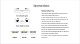
(Fig. 1).
m-2302
Figure 1
1. Model and serial number decal
For your convenience, write the product model and serial
numbers in the space below.
Model No:
Serial No.
Read this manual carefully to learn how to operate and
maintain your product correctly. Reading this manual will
help you and others avoid personal injury and damage to
the product. Although Toro designs, produces and markets
safe, state-of-the-art products, you are responsible for
using the product properly and safely. You are also
responsible for training persons who you allow to use the
product about safe operation.
The Toro warning system in this manual identifies
potential hazards and has special safety messages that help
you and others avoid personal injury, even death.
DANGER, WARNING and CAUTION are signal words
used to identify the level of hazard. However, regardless
of the hazard, be extremely careful.
3
DANGER signals an extreme hazard that will cause
serious injury or death if the recommended precautions
are not followed.
WARNING signals a hazard that may cause serious injury
or death if the recommended precautions are not followed.
CAUTION signals a hazard that may cause minor or
moderate injury if the recommended precautions are not
followed.
Two other words are also used to highlight information.
“Important” calls attention to special mechanical
information and “Note” emphasizes general information
worthy of special attention.
The left and right side of the machine is determined by
standing behind the handle in the normal operators
position.
Safety
Training
1. Read the instructions carefully. Be familiar with the
controls and the proper use of the equipment.
2. Never allow children or people unfamiliar with these
instructions to use the lawnmower. Local regulations
may restrict the age of the operator.
3. Never mow while people, especially children, or pets
are nearby.
4. Keep in mind that the operator or user is responsible
for accidents or hazards occurring to other people or
their property.
Preparation
1. While mowing, always wear substantial footwear and
long trousers. Do not operate the equipment when
barefoot or wearing open sandals.
2. Always wear safety glasses or eye shields during
operation to protect eyes from foreign objects that may
be thrown from the machine. Wearing of hearing
protection, protective gloves and a safety helmet is
advisable.
3. Thoroughly inspect the area where the equipment is to
be used and remove all objects which may be thrown
by the machine.
4. WARNING – Petrol is highly flammable.
Store fuel in containers specifically designed for this
purpose.
Refuel outdoors only and do not smoke while
refuelling.
Add fuel before starting the engine. Never remove the
cap of the fuel tank or add petrol while the engine is
running or when the engine is hot.
If petrol is spilled, do not attempt to start the engine
but move the machine away from the area of spillage
and avoid creating any source of ignition until petrol
vapors have dissipated.
Replace all fuel tanks and container caps securely.
5. Replace faulty silencers.
6. Before using, always visually inspect to see that the
blades, blade bolts and cutter assembly are not worn or
damaged. Replace worn or damaged blades and bolts
in sets to preserve balance.
7. On multi-bladed machines, take care as rotating one
blade can cause other blades to rotate.
Operation
1. Do not operate the engine in a confined space where
dangerous carbon monoxide fumes can collect.
2. Mow only in daylight or in good artificial light.
3. Avoid operating the equipment in wet grass, where
feasible.
4. Always be sure of your footing on slopes.
5. Walk, never run.
6. For wheeled rotary machines, mow across the face of
slopes, never up and down.
7. Exercise extreme caution when changing direction on
slopes.
8. Do not mow excessively steep slopes.
9. Use extreme caution when reversing or pulling the
lawnmower towards you.
10.Stop the blade(s) if the lawnmower has to be tilted for
transportation when crossing surfaces other than grass,
and when transporting the lawnmower to and from the
area to be mowed.
11. Never operate the lawnmower with defective guards or
shields, or without safety devices, for example
deflectors and/or grass catchers, in place.
12.Do not change the engine governor settings or
overspeed the engine.
13.Disengage all blade and drive clutches before starting
the engine.
14.Start the engine or switch on the motor carefully
according to instructions and with feet well away from
the blade(s).
4
15.Do not tilt the lawnmower when starting the engine or
switching on the motor, except if the lawnmower has
to be tilted for starting. In this case, do not tilt it more
than absolutely necessary and lift only the part which
is away from the operator.
16.Do not start the engine when standing in front of the
discharge chute.
17.Do not put hands or feet near or under rotating parts.
Keep clear of the discharge opening at all times.
18.Never pick up or carry a lawnmower while the engine
is running.
19.Stop the engine and disconnect the spark plug wire.
before clearing blockages or unclogging chute;
before checking, cleaning or working on the
lawnmower;
after striking a foreign object. Inspect the lawnmower
for damage and make repairs before restarting and
operating the lawnmower;
if lawnmower starts to vibrate abnormally (check
immediately).
20.Stop the engine
whenever you leave the lawnmower;
before refuelling.
21.Reduce the throttle setting during engine shut down
and, if the engine is provided with a shut-off valve,
turn the fuel off at the conclusion of mowing.
22.Go slow when using a trailing seat.
Maintenance and Storage
1. Keep all nuts, bolts and screws tight to be sure the
equipment is in safe working condition.
2. Never store the equipment with petrol in the tank
inside a building where fumes may reach an open
flame or spark.
3. Allow the engine to cool before storing in any
enclosure.
4. To reduce the fire hazard, keep the engine, silencer,
battery compartment and petrol storage area free of
grass, leaves, or excessive grease.
5. Check the grass catcher frequently for wear or
deterioration.
6. Replace worn or damaged parts for safety.
7. If the fuel tank has to be drained, this should be done
outdoors.
Sound Pressure Level
This unit has an equivalent continuous A-weighted sound
pressure at the operator ear of: 83.5 dB(A), based on
measurements of identical machines per ANSI
B71.5-1984 procedures.
Sound Power Level
This unit has a sound power level of: 100 dB(A)/1 pW,
based on measurements of identical machines per
Directive 84/538/EEC and amendments.
Vibration Level
This unit has a maximum hand-arm vibration level of
3.6 m/s@, based on measurement of identical machines per
ISO 5349 procedures.
5
Symbol Glossary
Safety alert triangle —
symbol within triangle
indicates a hazard.
Do not open or
remove safety shields
while engine is
running.
Safety alert symbol
Rotating blade can cut
off toes or fingers.
Stay clear of mower
blade as long as
engine is running.
Read operators
manual.
To avoid blade failure
when mulching, use
blade stiffener when
mower is equipped
with mulching plug.
Consult technical
manual for proper
service procedures.
Transmission
Stay a safe distance
from the machine.
Oil
Stay a safe distance
from the mower.
On/Run
Throw or flying
objects — Whole body
exposure
Engage
Thrown or flying
objects — Rotary
side-mounted mower.
Keep deflector shield
in place.
Disengage
Stop engine before
leaving operator
position.
Battery charging
condition
6
Hourmeter/elapsed
operating hours
Fuel
Fast Neutral
Slow First gear
Decreasing/Increasing Second gear
Grease lubrication
point
Third gear
Engine start
Cutting element —
basic symbol
Engine stop
Cutting element —
height adjustment
Choke Pull rope.
Primer (start aid) Wheel
7
Push primer three
times.
Wheel traction
Properly dispose of
batteries.
Lower control bar.
Insert key in ignition
switch.
Raise control bar.
Turn key in ignition
switch.
Raise/lower control
bar.
Move control.
Raise/lower control
bar.
Move control forward. Raise control bar.
Move control
rearward.
Raise control bar.
Lower control bar.
8
Assembly
Install Handles
1. Mount handle to outside of mower housing, using
bottom hole, with (2) 5/16–18 x 1–1/4” lg. capscrews,
washers, and thin nylon insert locknuts.
534
1
2
3
4
55
Figure 2
1. Handle
2. Handle latch
3. Bag support rod
4. Cap locknut
5. Cable tie
2. Secure handle latches to handle with (2) 5/16–18 x
1–1/2” lg. capscrews, washers and nylon insert
locknuts. Position locknuts and washers on inside of
handle.
Note: Handle height is adjustable for operator comfort.
Stand behind mower handle to gauge height. To adjust
handle height, reposition capscrews and locknuts securing
handle latches to handle into other mounting holes in
latches.
3. Slide bag support rod thru top mounting holes in
handle and secure each end with a cap locknut (Fig. 2).
4. Secure control cables in position with cable ties.
Install Gas Tank and Fuel Line
1. Start self–tapping screws into bottom of gas tank and
then remove screws.
2. Hook the plastic clips on the rear of the gas tank onto
gas tank bracket (Fig. 3).
m-2942
1
2
3
4
6
5
7
Figure 3
1. Self-tapping screws
2. Gas tank
3. Plastic clips
4. Gas tank retainer
5. Gas tank bracket
6. Locknut
7. Tank base
3. Secure gas tank to tank base with the (2) self–tapping
screws (Fig. 3). Do not overtighten screws.
4. Hook gas tank retainer onto gas tank and slide end of
retainer into hole in tank bracket. Secure retainer to
tank bracket with locknut (Fig 3). Do not overtighten.
5. Slide end of fuel line onto elbow fitting. Secure in
place with fuel line clamp (Fig. 4).
1
2
3

Figure 4
1. Fuel line
2. Elbow fitting
3. Fuel line clamp
9
Install Starter Rope
1. Pull the starter rope through the rope guide on the
handle (Fig. 5). To make the rope easier to loop,
squeeze the control bar on the handle to release the
blade brake.
1
2

Figure 5
1. Rope guide 2. Starter rope
Install Air Cleaner Cover
1. Insert bottom tabs of air cleaner cover into slots.
Rotate cover upwards and snap into place (Fig. 6).
196
1
2
3
Figure 6
1. Cover
2. Tabs
3. Foam element
Install Discharge Tunnel Plug
1. Open the discharge door by pulling forward on the
handle and moving it rearwards (Fig. 7). Hold the
discharge door handle to prevent the spring–loaded
door from closing while inserting the plug.
262
1
Figure 7
1. Plug rotated clockwise
2. Since the plug is slightly wider than the discharge
tunnel opening, rotate the plug clockwise slightly
while inserting it (Fig. 7). Make sure the arrow on the
plug decal is pointing upwards.
404
1
Figure 8
1. Spring clip
3. Push the plug all the way in until the spring clip on the
bottom of the plug clicks into place, locking the plug
securely into the discharge tunnel (Fig. 8). Release
discharge door handle to lock top of plug.
10
Before Starting
POTENTIAL HAZARD
In certain conditions gasoline is extremely
flammable and highly explosive.
WHAT CAN HAPPEN
A fire or explosion from gasoline can burn you,
others, and cause property damage.
HOW TO AVOID THE HAZARD
Use a funnel and fill the fuel tank outdoors, in
an open area, when the engine is cold. Wipe up
any gasoline that spills.
Do not fill the fuel tank completely full. Add
gasoline to the fuel tank until the level is 1/4” to
1/2” (6 mm to 13 mm) below the bottom of the
filler neck. This empty space in the tank allows
gasoline to expand.
Never smoke when handling gasoline, and stay
away from an open flame or where gasoline
fumes may be ignited by a spark.
Store gasoline in an approved container and
keep it out of the reach of children.
Never buy more than a 30-day supply of
gasoline.
Oil Mix Ratio
For simplicity and best engine performance, mix the
contents of one bottle of Toro 50:1 Two-Cycle Oil with
7.6 liters (two gallons) of fresh, unleaded regular gasoline.
Leaded regular gasoline may be used if unleaded regular
is not available.
Toro Two-Cycle Oil is specially formulated to provide
superior lubrication, make starting easy, and prolong
engine life. If Toro Two-Cycle Oil is not available, mix
7.6 liters (two gallons) of gasoline and 154 ml
(5.2 ounces) of another high grade two-cycle oil that has
the NMMA or BIA-TCW certification printed on the
label.
50:1 Gas/Oil Mixing Chart
Gasoline Oil
1 gallon 2.6 oz.
2 gallons 5.2 oz.
U.S. GALLON
Toro also recommends that Toro Stabilizer/Conditioner be
used regularly in all Toro gasoline powered products
during operation and storage seasons. Toro
Stabilizer/Conditioner cleans the engine during operation
and prevents gum-like varnish deposits from forming in
the engine during periods of storage.
IMPORTANT: Never use automotive oil (i.e. SAE 30,
10W30 etc.), two-cycle oil that is not certified
NMMA/BIA-TCW, or the wrong mix ratio because the
engine can be damaged, and it would not be covered by
the Toro warranty.
IMPORTANT: Never use methanol
, gasoline
containing methanol
, gasohol containing more than
10% ethanol, premium gasoline, or white gas because
engine fuel system damage could result.
Do not use fuel additives other than those
manufactured for fuel stabilization during storage such
as Toro’s stabilizer/conditioner or a similar product.
Toro’s stabilizer/conditioner is a petroleum distillate
based stabilizer/conditioner. Toro does not recommend
stabilizers with an alcohol base such as ethanol,
methanol or isopropyl. Stabilizers should not be used to
try to enhance the power or performance of machine.
Mixing Gasoline and Oil (Fig. 9)
1. Pour correct amount of gasoline into an approved
gasoline container and add the correct amount of
two-cycle oil.
2. Install cap on gasoline container and shake the
container to mix oil and gas thoroughly.
3. Remove cap and add remaining amount of gasoline.
Note: Do not mix gasoline and oil in the product fuel
tank. Oil that is at room temperature mixes easier and
more thoroughly than cold oil.
111
2 31
Figure 9
1. Add oil to small amount of
gasoline
2. Install cap and shake can
to mix
3. Add remaining amount of
gasoline
Recycler Mower Features
The Toro Recycler mower has a new and completely
different cutting concept that leaves your lawn with a
bagged look without bagging clippings.
Your Recycler mower is equipped with special parts
which increase your mowers ability to cut and recut grass
clippings, leaves, and other yard debris into tiny particles
and inject them down into the grass. These parts are:
A. A special blade and blade stiffener
11
B. Three special “kicker plates” positioned on the
underside of the mower deck in strategic positions
(Fig. 10)
757
1
Figure 10
1. Kicker plates
C. A special plug which locks into the mowers
discharge tunnel (a fourth kicker is on the plug)
(Fig. 11)
264
1
2
Figure 11
1. Kicker 2. Plug
The blade and three kicker plates are permanent parts of
your mower. The blade should be removed only for
sharpening or replacement. The kickers should never be
removed, unless they need to be replaced. They do not
interfere with the normal bagging or optional side
discharge operations of the mower.
WARNING
POTENTIAL HAZARD
Operating mower without stiffener in place
could cause blade to flex, bend or break.
WHAT CAN HAPPEN
A broken blade could cause serious injury or
death to operator or bystanders.
HOW TO AVOID THE HAZARD
Do not operate mower without stiffener.
The plug, however, is a removable part, just as the grass
bag and optional side discharge chute are removable parts.
You cannot use the plug in combination with either the
grass bag or the side discharge chute.
It is possible to mow without using the plug by closing the
discharge tunnel door. However, your lawn appearance
will be much more satisfactory if you use the plug as it
has an additional kicker (Fig. 11) that helps drive the
clippings down into the grass.
WARNING
Grass clippings and other debris can be thrown
from an open discharge tunnel with enough force
to cause personal injury. Never start or operate
the mower unless one
of the following is true:
The discharge tunnel plug is locked securely in
discharge tunnel.
The grass bag is locked in place.
The optional side discharge chute is locked in
place.
The discharge tunnel door is locked closed.
POTENTIAL HAZARD
Wet grass or leaves can cause you to slip and
contact blade.
WHAT CAN HAPPEN
Blade contact can seriously injure you.
HOW TO AVOID THE HAZARD
Mow only in dry conditions.
12
Cutting Grass
Grass grows at different rates at different times of the
year. In the heat of the summer, it is generally best to
cut grass at the 44 mm (1-#/4”), 57 mm (2-!/4”) or 70
mm (2-#/4”) height-of-cut settings (Fig. 12). Only
about !/3 of the grass blade should be cut off. Cutting
below the 44 mm (1-#/4”) setting is not recommended
unless grass is sparse or it is late fall when grass
growth begins to slow down.
976
19mm
83mm
70mm 57mm 44mm 32mm
Figure 12
When cutting grass over 15 cm (six inches) tall, you
may want to first mow using the highest height-of-cut
setting and a slower walking speed; then mow again at
a lower setting for best lawn appearance. If grass is too
long and leaves clumps on top of lawn, mower may
plug and cause engine to stall.
Alternate mowing direction. This helps disperse
clippings over lawn for even fertilization.
If the finished cut lawn appearance is unsatisfactory, try
one or more of the following:
Sharpen the blade.
Walk at a slower pace while mowing.
Raise the height-of-cut setting on your mower.
Cut grass more frequently.
Overlap cutting swaths instead of cutting a full swath
with each pass.
Mow across the marginal areas a second time.
Set height-of-cut on front wheels one notch lower than
rear wheels. (example: set front wheels at 44 mm
(1-#/4”) setting and rear wheels at 57 mm (2-!/4”)
setting)
Tips For Cutting Leaves
You can cut up leaves in the fall instead of bagging. If you
decide to bag, the Recyclerr mower reduces the number
of leaf bags you will need by finely chopping up the
leaves before they are bagged. Some leaf particles will be
injected back down into the soil. When spring arrives, the
leaf particles will have decomposed and returned valuable
nutrients to the soil.
Ensure leaves are dry.
When cutting is complete, always be sure that 50% of
the lawn shows through the cut leaf cover. This may
require one or more passes over the leaves.
For light leaf coverage, position all wheels at the same
height-of-cut setting.
If there are more than 5” of leaves on lawn, set the
front wheels one or two notches higher than the rear
wheels. This makes it easier to feed leaves under
mower deck.
Walk at a slower mowing speed if leaves are not being
cut up finely enough to be hidden down in the grass.
If you cut up a lot of oak leaves, you might want to
add lime to your grass in the spring. Lime reduces the
acidity of oak leaves.
Mow across the marginal areas a second time.
Set height-of-cut on front wheels one notch lower than
rear wheels. (example: set front wheels at 44 mm
(1-#/4”) setting and rear wheels at 57 mm (2-!/4”)
setting)
Tips For Cutting Leaves
You can cut up leaves in the fall instead of bagging. If you
decide to bag, the Recyclerr mower reduces the number
of leaf bags you will need by finely chopping up the
leaves before they are bagged. Some leaf particles will be
injected back down into the soil. When spring arrives, the
leaf particles will have decomposed and returned valuable
nutrients to the soil.
Ensure leaves are dry.
When cutting is complete, always be sure that 50% of
the lawn shows through the cut leaf cover. This may
require one or more passes over the leaves.
For light leaf coverage, position all wheels at the same
height-of-cut setting.
If there are more than 5” of leaves on lawn, set the
front wheels one or two notches higher than the rear
wheels. This makes it easier to feed leaves under
mower deck.
Walk at a slower mowing speed if leaves are not being
cut up finely enough to be hidden down in the grass.
13
If you cut up a lot of oak leaves, you might want to
add lime to your grass in the spring. Lime reduces the
acidity of oak leaves.
Operation
Starting, Stopping, And
Self–propelling
1. CONTROLS—Throttle, ground speed control, blade
control bar, self-propel control bar and fingertip starter
are on upper handle (Fig. 13).
m-4325
1
2
3
4
5
Figure 13
1. Throttle
2. Blade control bar
3. Self-propel control bar
4. Fingertip starter
5. Ground speed control
2. Push wire onto spark plug.
3. STARTING—Move ground speed control to neutral
and throttle to
(CHOKE). Cover hole in center of
primer with thumb and push once. Squeeze blade
control bar against handle. Pull fingertip starter out
until positive engagement results; then pull vigorously
to start the engine. Regulate throttle as desired when
engine starts.
Note: When starting a warm engine,
CHOKE may
not be necessary.
4. Move ground speed control to desired speed selection
(Fig. 13).
5. TRACTION OPERATION—Squeeze self-propel
control bar against handle to drive. Ground speed
varies, depending on space between control bar and
handle (Fig. 13).
6. STOPPING—To stop the self–propel drive, release the
self-propel control bar. To stop engine, release blade
control bar. Pull wire off spark plug if mower will be
unattended or not used.
Using Discharge Tunnel Plug
1. Make sure engine is off. Open the discharge door by
pulling forward on the handle and moving it rearwards
(Fig. 14). Hold the discharge door handle to prevent
the spring–loaded door from closing while inserting
the plug.
2. Since the plug is slightly wider than the discharge
tunnel opening, you must rotate the plug clockwise
slightly while inserting it (Fig. 14). Make sure the
arrow on the plug decal is pointing upwards.
262
1
Figure 14
1. Plug rotated clockwise
3. Push the plug all the way in until the spring clip on the
bottom of the plug clicks into place, locking the plug
securely into the discharge tunnel (Fig. 15). Release
the discharge door handle to lock the top of the plug.
4. To remove the plug, move the discharge door handle
rearwards while at the same time lift up the spring clip
on the bottom of the plug. When the plug is unlocked,
pull it out of the discharge tunnel.
14
404
1
Figure 15
1. Spring clip
Using Grass Bag
Occasionally you may wish to use the grass bag for
bagging extra long grass, lush grass or leaves.
1. Stop engine and wait for all moving parts to stop.
2. Ensure discharge door handle is fully forward and pin
is engaged in catch (Fig. 16).
m-1912
1
2
3
Figure 16
1. Bag frame on retaining
post
2. Pin engaged in catch
3. Handle fully forward.
Discharge door closed.
3. INSTALLING BAG—Slide hole in bag frame onto
retaining post on discharge tunnel (Fig. 16). Set rear of
bag frame onto lower handle.
DANGER
POTENTIAL HAZARD
Grass clippings and other objects can be
thrown from an open discharge tunnel.
WHAT CAN HAPPEN
Objects thrown with enough force could cause
serious personal injury or death to operator or
bystander.
HOW TO AVOID THE HAZARD
Never open door on discharge tunnel when
engine is running unless the grass bag, optional
side discharge attachment or discharge tunnel
plug is securely installed.
DANGER
POTENTIAL HAZARD
A worn grass bag could allow small stones and
other similar debris to be thrown in operator’s
or bystander’s direction.
WHAT CAN HAPPEN
Thrown objects can cause serious personal
injury or death to operator or bystanders.
HOW TO AVOID THE HAZARD
Check the grass bag frequently. If it is
damaged, install a new genuine TORO
replacement bag.
m-1913
1
Figure 17
1. Pin locked in bag notch
15
4. Pull discharge door handle forward until pin clears
catch and move handle rearward until pin locks in bag
notch (Fig. 17). Discharge door in mower housing is
now open.
DANGER
POTENTIAL HAZARD
Thrown objects may result if discharge door
does not close completely.
WHAT CAN HAPPEN
Thrown objects can cause serious
personal injury or death.
HOW TO AVOID THE HAZARD
If discharge door cannot be closed because
grass clippings clog discharge area, stop engine
and gently move discharge door handle back
and forth until door can be closed completely. If
door still cannot be closed, remove obstruction
with a stick, not your hand.
5. EMPTYING BAG—Stop engine and wait for all
moving parts to stop. Raise discharge door handle and
move it forward to engage the locking pin with catch
(Fig. 16). Grasp handles at front and rear of bag and
lift bag off mower. Gradually tip bag forward to empty
clippings.
6. To reinstall bag, repeat steps 3-4.
Adjusting Height–of–cut
The height–of–cut is adjustable from approximately
19 mm to 83 mm (3/4 to 3–1/4 inches), in 12.7 mm (1/2
inch) increments. Moving height–of–cut adjuster forward
raises height–of–cut.
1. Stop the engine.
DANGER
POTENTIAL HAZARD
Adjusting height-of-cut levers could bring
hands into contact with moving blade.
WHAT CAN HAPPEN
Contact with blade could cause serious personal
injury.
HOW TO AVOID THE HAZARD
Stop engine and wait for all moving parts to
stop before changing height-of-cut.
Do not put fingers under housing to lift mower
when adjusting height-of-cut levers.
2. For easier adjustment, lift housing up so wheel is off
ground. Do not place hands under deck to lift
housing. Squeeze adjusting lever toward wheel
(Fig. 18) and move it to the desired setting. Ensure pin
on adjusting lever engages notch in mower housing
wear plate. Adjust all wheels to the same setting.
225
Figure 18
16
Maintenance
CAUTION
POTENTIAL HAZARD
Engine could start accidentally.
WHAT CAN HAPPEN
Accidental starting of engine could cause
serious injury to operator or
bystanders.
HOW TO AVOID THE HAZARD
Pull wire off spark plug before performing any
maintenance or adjustments.
Servicing Air Cleaner
Normally, clean air cleaner after every 25 operating hours.
More frequent cleaning is required when mower is
operated in dusty or dirty conditions.
1. Stop engine and pull wire off spark plug (Fig. 19).
2. Lift tabs at top of air cleaner cover and pivot cover
down. Clean cover thoroughly (Fig. 19).
196
1
2
3
4
Figure 19
1. Spark plug wire
2. Primer
3. Cover
4. Foam element
3. If outside of foam element is dirty, remove it from air
cleaner body (Fig. 19). Clean thoroughly.
A. WASH foam element in a solution of liquid soap
and warm water. Squeeze to remove dirt, but do
not twist because foam may tear. Rinse thoroughly
in clear water.
B. DRY by wrapping in a clean rag. Squeeze rag and
foam element to dry.
C. SATURATE element with engine oil. Squeeze
element to remove excess oil and to distribute oil
thoroughly. A damp element is desirable.
4. Reinstall foam element and air cleaner cover.
IMPORTANT: Do not operate engine without air
cleaner element because extreme engine wear and
damage will likely result.
Replacing Spark Plug
Use an NGK BPMR4A spark plug or equivalent. Correct
air gap is 0.81 mm (0.032”). Remove plug after every 25
operating hours and check its condition.
1. Stop engine and pull wire off spark plug.
2. Clean around spark plug and remove plug from
cylinder head.
IMPORTANT: Replace a cracked, fouled, or dirty
spark plug. Do not sand blast, scrape, or clean
electrodes because engine damage could result from
grit entering cylinder.
3. Set air gap at 0.81 mm (0.032”) (Fig. 20). Install
correctly gapped spark plug and gasket seal. Tighten
plug firmly to 13.6 Nm (10 ft–lb).
110
0.81 mm
(0.032")
Figure 20
Draining Gasoline
1. Stop engine. Pull wire off spark plug.
Note: Drain gasoline from a cold engine only.
2. Remove cap from fuel tank and use pump–type syphon
to drain fuel into clean gas can.
Note: This is the only procedure recommended for
draining fuel.
Adjusting Throttle
Throttle control adjustment may be required if engine
does not start. Whenever a new throttle control cable is
installed, throttle must be adjusted.
1. Stop engine and pull wire off spark plug.
2. Move throttle control to
(FAST).
3. Loosen cable clamp screw until throttle cable slides
(Fig. 21). Align holes in choke arm and throttle
bracket. A small dia. pin may be inserted into aligned
17
holes to hold adjustment. Push throttle cable until
throttle arm makes contact with choke arm. Tighten
cable clamp. Remove pin if used.
780
1
2
3
4
Figure 21
1. Throttle arm
2. Choke arm
3. Aligned holes
4. Throttle bracket
Cleaning Cooling System
After every 75 operating hours, clean dirt and chaff from
cylinder, cylinder head fins and from around carburetor
and linkage. Also remove debris from air intake slots on
recoil housing. This will ensure proper cooling and best
engine performance.
Cleaning Muffler And Exhaust
Port
Clean end of muffler pipe and exhaust port after every 75
hours of operation.
CAUTION
POTENTIAL HAZARD
Muffler and engine surface become hot when
mower is in operation.
WHAT CAN HAPPEN
Contact with hot muffler surface could cause a
burn.
HOW TO AVOID THE HAZARD
Clean muffler and exhaust port only after
engine and muffler are cool.
1. Use hard wood scraper and remove carbon from end of
muffler pipe (Fig. 22).
202
1
2
Figure 22
1. Screws, nuts and
lockwashers
2. Muffler pipe
2. Remove screw, two nuts, and lockwashers (Fig. 22).
Slide muffler off mounting pins.
3. Pull wire off spark plug. Slowly pull recoil starter so
piston covers exhaust port (Fig. 23).
4. Clean carbon from exhaust port (Fig. 23) with flat,
hard wood scraper.
IMPORTANT: Do not use a metal scraper or similar
object to clean exhaust port because accidental damage
to the piston or cylinder could easily occur.
5. Reinstall muffler with screw, (2) nuts and lockwashers
(Fig. 22). After cleaning exhaust port, make sure
muffler gasket is still usable.
203
1
Figure 23
1. Exhaust port
Adjusting Wheel Drive
If mower does not self–propel or has a tendency to creep
forward when drive is not engaged, adjust wheel drive
control knob on rear of gear box.
18
1. If necessary, remove grass bag.
2. ADJUSTMENT (Fig. 24)—Rotate control knob
clockwise 1/2 turn if mower does not self–propel. If
mower creeps forward, rotate knob 1/2 turn
counterclockwise to loosen belt.
m-4315
1
Figure 24
1. Control knob
3. CHECK ADJUSTMENT—Slowly pull mower
backward while self-propel control bar is gradually
moved toward handle. Adjustment is correct when rear
wheels stop turning and self-propel control bar is about
25 m (1 inch) from handle (Fig. 25).
4. Repeat steps 2 and 3 until properly adjusted.
m-4323
2,5 CM
(1 INCH)
Figure 25
Adjusting Ground Speed
Control Cable
1. Move the ground speed control (Fig. 13) to N
(neutral). Make sure the control is all the way back in
the N slot.
2. Loosen the clamp screw (Fig. 26).
m–4326
1
2
3
4
Figure 26
1. Clamp screw
2. Shift lever
3. Stop
4. Ground speed cable
3. Push the shift lever until it is tight against the stop
(Fig. 26).
4. Pull all slack out of the ground speed cable and tighten
the clamp screw.
If the mower does not drive when the ground speed
control is in one of the three speed slots, make sure the
ground speed control is positioned fully forward in the
desired speed slot.
Inspecting/Removing/
Sharpening Blade
1. Stop engine and pull wire off spark plug.
19
2. Drain gasoline from fuel tank; refer to Draining
Gasoline, page 16.
3. Tip mower on its right side (Fig.27). Avoid rotating
blade. Starting problems may result.
757
1
2
3
Figure 27
1. Blade
2. Blade bolt and lockwasher
3. Blade accelerator
4. INSPECTING BLADE—Carefully examine blade for
sharpness and wear, especially where flat and curved
parts meet (Fig. 28A). Since sand and abrasive
material can wear away the metal that connects the flat
and curved parts of the blade, check blade before using
the mower. If a slot or wear is noticed, (Fig. 28B & C),
replace blade. Refer to step 5.
Note: For best performance, install new blade before
cutting season begins. During the year, file down small
nicks to maintain the cutting edge.
DANGER
POTENTIAL HAZARD
A worn or damaged blade could break and a
piece of blade could be thrown into operator’s
or bystander’s area.
WHAT CAN HAPPEN
A thrown piece of blade could cause serious
personal injury or death to
operator or bystanders.
HOW TO AVOID THE HAZARD
Inspect blade periodically for wear or damage.
Replace a worn or damaged blade.
5. REMOVING BLADE—Grasp end of blade using a rag
or thickly padded glove. Remove blade bolt,
lockwasher, blade accelerator and blade (Fig. 27).
270
A
B
C
1
2
3
4
Figure 28
1. Sail
2. Flat part of blade
3. Wear
4. Slot formed
6. SHARPENING BLADE—Using a file, sharpen top
side of blade and maintain original cutting angle
(Fig. 29). The blade will remain balanced if same
amount of material is removed from both cutting
edges.
153
1
Figure 29
1. Sharpen at this angle only
IMPORTANT: Check balance of blade by putting it on
a blade balancer. An inexpensive balancer can be
purchased at a hardware store. A balanced blade stays
in a horizontal position and an unbalanced blade settles
to the heavy side. If blade is not balanced, file more
metal off cutting edge on heavy end of blade.
7. Install sharp, balanced blade, blade accelerator,
lockwasher and blade bolt. Sail part of blade must
point toward top of mower housing to ensure correct
installation. Tighten blade bolt to 68 Nm (50 ft–lb).
20
WARNING
POTENTIAL HAZARD
Operating mower without accelerator in place
could cause blade to flex, bend or break.
WHAT CAN HAPPEN
A broken blade could cause serious injury or
death to operator or bystanders.
HOW TO AVOID THE HAZARD
Do not operate mower without accelerator.
Lubrication
After every 25 operating hours or when season ends, pivot
arms must be lubricated.
1. Move rear wheel height–of–cut levers to center
setting. Wipe grease fittings with clean rag (Fig. 30).
Install grease gun onto fitting and gently apply 2 or 3
pumps of #2 Multi–Purpose Lithium Base Grease.
Excessive pressure may damage seals.
232
1
Figure 30
1. Grease fitting
Lubricating Gear Case
After every 100 operating hours, grease the gear case with
#2 Multi–Purpose Lithium Base Grease.
1. Install grease gun onto fitting thru belt cover opening
(Fig. 31). Gently apply 1–2 pumps of grease.
m-4316
1
Figure 31
1. Grease fitting
Servicing Wheels
Removal
1. Remove capscrew, wheel spacer, and locknut
mounting wheel to pivot arm (Fig. 32).
209
112345
567 7 8 9
Figure 32
1. Locknut (4)
2. Wheel spacer
3. Bearing support hub
4. Bearing spacer
5. Wheel half
6. Plastic cover (rear wheels
only)
7. Lug
8. Bearing (2)
9. Capscrew
2. Separate wheel halves from tire by removing (4)
capscrews and locknuts (Fig. 32).
Note: If bearings are to be removed from bearing support
hub, remove by pressing on bearing spacer.
Assembly
1. Position tire onto (1) wheel half, aligning lugs on each
(Fig. 32).
  • Page 1 1
  • Page 2 2
  • Page 3 3
  • Page 4 4
  • Page 5 5
  • Page 6 6
  • Page 7 7
  • Page 8 8
  • Page 9 9
  • Page 10 10
  • Page 11 11
  • Page 12 12
  • Page 13 13
  • Page 14 14
  • Page 15 15
  • Page 16 16
  • Page 17 17
  • Page 18 18
  • Page 19 19
  • Page 20 20
  • Page 21 21
  • Page 22 22
  • Page 23 23
  • Page 24 24

Toro 53cm Lawnmower User manual

Category
Lawnmowers
Type
User manual

Toro 53cm Lawnmower: Tackle your lawn with ease and precision using this powerful and versatile machine. Designed for medium to large-sized gardens, it boasts a robust cutting deck and efficient mulching capabilities, ensuring a neat and healthy lawn. Experience effortless mowing with self-propulsion and variable speed control, allowing you to customize your mowing pace. Maintain a pristine lawn with Toro's reliable performance and innovative features.

Ask a question and I''ll find the answer in the document

Finding information in a document is now easier with AI