Installation instructions
Inclination sensor JD
80294704/00 05/2020
1 Preliminary note
You will find the device manual, technical data, approvals, accessories and further
information at www.ifm.com.
2 Safety instructions
• The device described is a subcomponent for integration into a system.
- The manufacturer is responsible for the safety of the system.
- The system manufacturer undertakes to perform a risk assessment and to
create a documentation in accordance with legal and normative requirements
to be provided to the operator and user of the system. This documentation
must contain all necessary information and safety instructions for the operator,
the user and, if applicable, for any service personnel authorised by the
manufacturer of the system.
• Read this document before setting up the product and keep it during the entire
service life.
• The product must be suitable for the corresponding applications and
environmental conditions without any restrictions.
• Only use the product for its intended purpose (→ 3 Function and features).
• If the operating instructions or the technical data are not adhered to, personal
injury and/or damage to property may occur.
• The manufacturer assumes no liability or warranty for any consequences
caused by tampering with the product or incorrect use by the operator.
• Installation, electrical connection, set-up, programming, configuration, operation
and maintenance of the product must be carried out by personnel qualified and
authorised for the respective activity.
• Protect units and cables against damage.
3 Functions and features
Dynamic MEMS inclinometers sense and measure the angle of tilt (inclination/
slope/elevation) of an object.
JD1xxx: 1-axis sensor with angular range 0...360° (vertical installation).
JD2xxx: 2-axis sensor with angular range ±90° (horizontal installation).
4 Installation
► Choose a level mounting surface.
► Fix the unit using 4 screws, tightening torque 1.5...2.5 Nm.
Recommendation:
M6 screws or ¼” UNC screws
► Adjust M12 connectors precisely and screw them fully into the unit, tightening
torque 1.5 Nm.
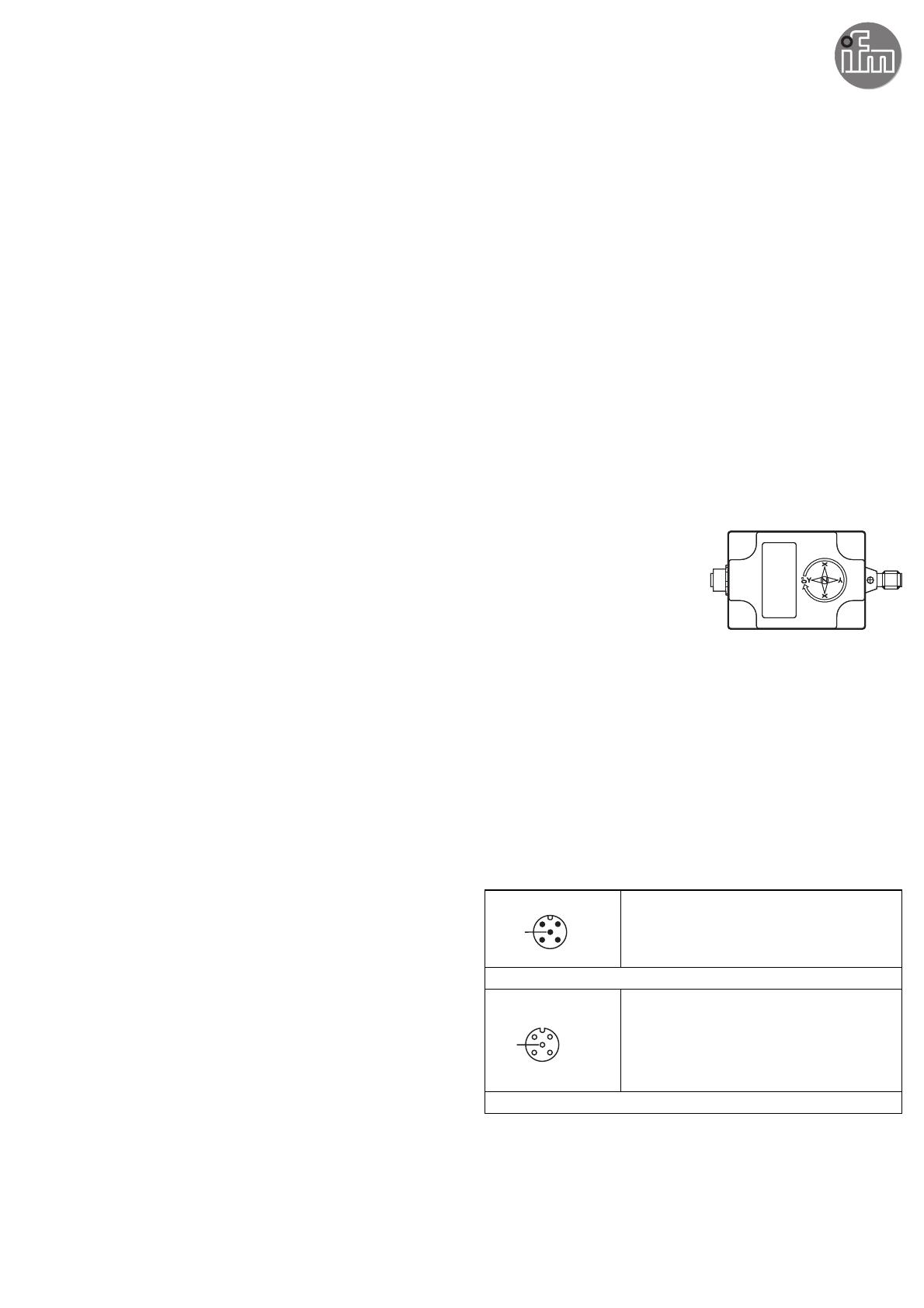
5 Electrical connection
The inclinometer is connected via a 5-pin M12 connector.
Pin configuration
4
21
3
5
1: CAN _GND
2: Supply voltage 24 V DC (+U
B
)
3: GND
4: CAN_H High bus cable
5: CAN_L Low bus cable
M12 connector CAN-In
3
12
4
5
1: CAN _GND
2: Supply voltage 24 V DC (+U
B
)
3: GND
4: CAN_H High bus cable
5: CAN_L Low bus cable
M12 socket CAN-Out
5.1 Bus termination
The sensor has a terminating resistor that can be enabled (120 Ω). Depending on
the interface, this resistor can be activated via the software (default: deactivated).
