AVLink DVI-EH Owner's manual
- Category
- Console extenders
- Type
- Owner's manual

DVI
EXTENDER
DVI-LH
(Local)
DVI-RH
(Remote)
USER MANUAL V1.2
DVI-EH
Package Contents-
DVI Extender Local Unit
DVI Extender Remote Unit
1 user manual
2 power adapter DC 5V 1A
Any thing missed, please contact with your vendor.
Introduction
The extension of DVI-D video signal device up to 30/50
meter away by using DVI extender and two CAT.5 cables.
DVI extender is ideal for:
Test bench facilities
Data Center
Help desks
Features
PC resolution to 1600x1200 60Hz / 30 meter.
PC resolution to 1280x1024 60Hz / 50 meter.
HDTV resolution up to 1080i / 50 meter.
Compliant with the specification of DVI 1.0.
Support DVI-D.
Support DDC & HDCP.
Use CAT.5 cable to install easily.
Specifications
Function DVI-LH
DVI-RH
Input Connector 1 DVI Female 2 RJ-45 Female
Output Connector 2 RJ-45 Female 1 DVI Female
Max. Resolution
1600x1200 60Hz /
1280x1024 60Hz, 1080i
Cable Distance 30/50 m (Max.)
Power Adapter (Min.) DC 5V 1A
Housing Metal
Weight 145g 142g
Dimensions (LxWxH) 67x52x38 mm
-1-
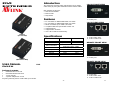
LOCAL FRONT VIEW
1. “DVI In” Port
2. Power Jack
LOCAL REAR VIEW
1. Power LED
2. “CAT.5” DDC Port
3. “CAT.5” Video Port
REMOTE FRONT VIEW
1. “DVI Out” Port
2. Power Jack
REMOTE REAR VIEW
1. Power LED
2. “CAT.5” DDC Port
3. “CAT.5” Video Port
-2-

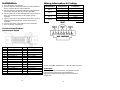
Installation
1. Turn off the PC and monitor.
2. Connect the DVI male/male extension cable between
the PC and the “DVI In” port of DVI-LH.
3. Connect the DVI male/male extension cable between
the monitor and the “DVI Out” port of DVI-RH.
4. Connect the CAT.5 cable between the DVI-LH “CAT.5”
DDC port and the DVI-RH “CAT.5” DDC port of
extender.
5. Connect the CAT.5 cable between the DVI-LH “CAT.5”
Video port and the DVI-RH “CAT.5” Video port of
extender.
6. Connect the power cord and turn on the extender.
7. Turn on the PC and monitor.
Technical Specifications
Input/Output Signal
Pin # Signal Pin # Signal
1
T.M.D.S Data 2-
16
Hot Plug Detect
2
T.M.D.S Data 2+
17
T.M.D.S Data 0-
3
T.M.D.S Data 2/4 Shield
18
T.M.D.S Data 0+
4
T.M.D.S Data 4-
19
T.M.D.S Data 0/5 Shield
5
T.M.D.S Data 4+
20
T.M.D.S Data 5-
6
DDC Clock
21
T.M.D.S Data 5+
7
DDC Data
22
T.M.D.S Clock Shield
8
Analog Vert. Sync
23
T.M.D.S Clock+
9
T.M.D.S Data 1-
24
T.M.D.S Clock-
10
T.M.D.S Data 1+
11
T.M.D.S Data 1/3 Shield
C1
Analog Red
12
T.M.D.S Data 3-
C2
Analog Green
13
T.M.D.S Data 3+
C3
Analog Blue
14
+5V Power
C4
Analog Horz Sync
15
GND
C5
Analog Ground
-3-
Wiring Information & Coding
Conductor
Identification
RJ45 Pin
Assignment
Color Code for
Conductor
5 White-Blue
Pair 1
4 Blue
1 White-Orange
Pair 2
2 Orange
3 White-Green
Pair 3
6 Green
7 White-Brown
Pair 4
8 Brown
© C&C TECHNIC TAIWAN CO., LTD. All rights reserved.
Trademarks:
All the companies, brand names, and product names
referred to this manual are the trademarks or
registered trademarks belonging to their respective
companies.
-4-
-
 1
1
-
 2
2


AVLink DVI-EH Owner's manual
- Category
- Console extenders
- Type
- Owner's manual
Ask a question and I''ll find the answer in the document
Finding information in a document is now easier with AI
Related papers
Other documents
-
Black Box DVI-D Extender User manual
-
-
Ihse Draco K477 Series User manual
-
-
PTN MMX6464 User manual
-
Thor TH-SSM User manual
-
KanexPro HDMMX3232-4K User manual
-
Digitus DC-40200 Owner's manual
-
Furuno HD32T22FUDMA4AOGP User manual
-