Page is loading ...

OPERATING/SERVICE MANUAL
FPL 44
QUICK START
In deference to the ecological movement, Rane has made a commitment to keep its manuals
short and to the point. After all, we’re in the electronics business, not the tree industry. In
deference to your patience, we include this hurry-up section.
Inputs on the FPL 44 are 1/4" TRS balanced/unbalanced. Outputs are balanced 3-pin (XLR).
Positive appears on the tip of the input and pin 2 on the output; negative is the ring of the input
and pin 3 on the output. Signal ground is either sleeve or pin 1.
Front panel settings include four THRESHOLD controls, four BYPASS switches and four
SLAVE switches. The THRESHOLD controls set the level at which output limiting occurs.
BYPASS directly connects the input to the output. The AUTO-SLAVE switch connects the VCA in
the channel to the “slave” bus. In this position all channels in AUTO-SLAVE limit by the same
amount when any one channel exceeds its threshold level. The channels may be. set at different
thresholds to suit the requirements of each situation. If one channel is overdriven by, say, 10 dB,
its gain and the gain of all others in the slave mode reduces by the same 10 dB.
NEVER CONNECT A NYTHING EXCEPT AN APPROVED RANE AC POWER SUPPLY
TO THE THING THAT LOOKS LIKE A RED TELEPHONE JACK ON THE REAR OF
THE FPL 44. This is an AC power input and requires special attention if you do not have a
power supply EXACTLY like the one originally supplied with your unit. A Rane Model FRS 8 or
RAP 10 power supply is acceptable as well. Please see the full explanation of power supply
requirements elsewhere in this manual.
When connecting the FPL 44 to other components of a sound system for the first time, LEAVE
THE POWER SUPPLY FOR LAST. This allows for any mistakes to be identified by visual inspec-
tion and corrected before power is applied and it becomes too late.
INPUTS on the FPL 44 are balanced. The hardware provided for input connectors are 1/4" tip-
ring-sleeve jacks. The tip of the jack is the positive input, the ring is the negative input and the
sleeve is signal ground. Unbalanced inputs may either ground the ring or leave it open while driv-
ing the tip with the unbalanced signal. The FPL 44’s input circuitry is of the instrumentation vari-
ety, eliminating concern over open negative inputs, while ensuring equal differential and
common-mode impedances.
OUTPUTS. The outputs on this device are balanced as well. They differ from the inputs only by
way of their hardware implementation. The Flex philosophy dictates using 1/4" connectors for sig-
nal flow inside of a rack. Lines likely to exit a rack are of the 3-pin variety. If you read the “Quick
Start” section above, you already know that pin 2 of the output connectors is positive, pin 3 is nega-
tive and pin 1 is signal ground.
POWERING UP. In the opening paragraph it was stated that a good visual inspection often elimi-
nates disasters before applying power. It cannot be overstated how important it is to use the correct
power supply with this and all Flex modules. The Rane RS 1 single AC power supply (included
with each module) as well as the Rane FRS 8 and RAP 10 power supplies are the only power sup-
plies certain to work properly with this limiter. If another power supply is to he considered, it must
be an AC supply. It must have an 18 to 24 volt center-tapped output and be wired to a 6-pin mod
connector in accordance with the requirements of the Rane standard.
SYSTEM CONNECTION

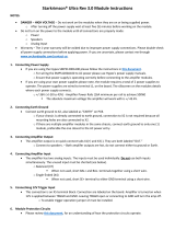
1. CHANNEL BYPASS SWITCH. This switch provides a passive bypass of each chan-
nel of the FPL 44. When pressed in, it directly connects the positive, negative and signal
ground inputs to the positive, negative and signal ground outputs of the channel. It is pro-
vided to allow easy A/B comparison of limiter activity. It also serves to pass the audio sig-
nal around the active circuitry of the limiter in the event of power failure.
2. BYPASS INDICATOR. This red LED illuminates to advise the operator of a bypass
condition, i.e., BYPASS switch pressed in.
3. LIMIT THRESHOLD CONTROL & INDICATOR. The calibrations (in dBu,
0 dBu = 0.776 Vrms) around this knob indicate the point at which the output limits. All lev-
els higher than this setting are reduced to this preset amplitude. The indicator illuminates
when the preset threshold is exceeded.
4. AUTO-SLAVE SWITCH. In the INDEPENDENT position (“down” in the vertical
orientation,
“right” when horizontally mounted) each limiter channel operates separately.
In the AUTO-SLAVE position (“up” in the vertical orientation, “left” in the horizontal),
each channel limits the same amount that any other channel in the slave mode does. If only
one channel of the possible four is set to this mode, it operates independently. If two or
more are set to AUTO-SLAVE, all slaved channels will attenuate the same amount when
any one exceeds its THRESHOLD.
5. POWER INDICATOR. This yellow LED illuminates when an appropriate power sup
ply is connected to the FPL 44 and is, itself, connected to an appropriate power source.
For the definition of “appropriate power supply,” please refer to the front page of this man-
ual. It doesn’t really make a lot of sense to beat this issue to death alter having done so
twice on the first page.
FRONT PANEL DESCRIPTION

REAR PANEL DESCRIPTION
1. 3-PIN OUTPUT CONNECTOR. One of four, this connector provides either a balanced
output on pins 2 and 3 or an unbalanced output between pins 2 and 1. Pin 2 is positive, pin 3
is negative and pin 1 is signal ground.
2. 1/4" TRS INPUT CONNECTOR. Each of the four channels of the FPL 44 makes use of
one of these to supply either a balanced or unbalanced input to the limiter circuitry within.
For balanced operation, the positive signal is applied to the tip, the ring receives the negative
and the sleeve is to be used for signal ground connection. Unbalanced input may be applied to
each channel by driving the tip and using both ring and sleeve for signal ground or the sleeve
alone. The simplest unbalanced input connection is realized by using a tip-sleeve (often re-
ferred to as a mono) plug which eliminates the need for ring worry.
3. GROUND LIFT SWITCH. This switch (mounted on the side) provides the ability to sep-
arate chassis ground and signal ground. Normally, this switch should be in the LIFT position
(pull toward the rear). In some circumstances it may be necessary to move it to the opposite
position to eliminate stubborn hum and buzz problems.
We realize a scientific explanation of this switch would be helpful, unfortunately science
doesn’t seem to have much to do with it. See the CHASSIS GROUNDING note on the last
page for details.
CAUTION: If you are tempted to try moving this switch with your power amplifiers turned
on or turned up, DON’T BE. ALWAYS TURN YOUR AMPLIFIER LEVELS DOWN BE-
FORE CHANGING YOUR GROUNDS AROUND and then bring them up slowly.
4. POWER INPUT CONNECTOR. This is the spot where the “appropriate power supply”
connects. Again, for a complete definition of the power supply, look across to the facing page
for information concerning the location nearest you.
5. GROUND CONNECTOR. Since the FPL 44 is powered from a remote AC power sup-
ply which does not carry chassis ground through to the grounding pin of the AC cord, this
threaded hole has been provided in case your system does not have another earth grounding
means such as through rack rails, etc. Its use or disuse should be determined by your specific
application.

OPERATING INSTRUCTIONS
To give you a better understanding about the operation of
the FPL 44, a quick course in its design should be useful.
Included as a part of this manual is the data sheet covering
this product. This sheet includes a block diagram of one
channel of the unit. You may want to consult this document
to aid you in understanding the following.
The limiter circuit used in this module is what Rane refers
to as a “servo-locked limiter.““’ This term derives from the
similarity of this design to that of a servo motor such as is
used in robotics and precision control systems. When the
output of the circuit is below the setting of the THRESH-
OLD control, the FPL 44 channel acts only as a unity gain
amplifier. The output is monitored at all times by a differen-
tial amplifer. One input of this differential amplifier has a
reference voltage connected to it. The other input is driven
by a full-wave rectifier whose level is a product of the
RMS output voltage of the voltage controlled amplifier
(hereafter VCA) and the THRESHOLD setting. The output
of this circuit produces an error voltage any time the
rectifier’s output exceeds the fixed reference. By nature, a
differential amplifier’s output travels wherever necessary in
terms of output voltage to keep its two inputs equal. Since
the output of this amplifier connects to the control pin of
the VCA, we have provided a means for this to occur. This
scheme creates a servo-loop which will not allow the output
of the VCA to increase above the THRESHOLD setting.
Any time the FPL 44 is limiting, the error signal created
by the servo amplifier will be proportional to the amount of
overdrive on its VCA’s output. This control voltage may
be connected to other VCAs in the FPL 44 by setting the
switch on the front panel to the AUTO-SLAVE position.
Doing so connects the VCA’s control pin to the slave bus
in the unit. In this way, when one channel limits, all chan-
nels on the bus attenuate the same amount. This preserves
the spectral distribution of the signal.
This is a rather brief comment on the internal workings of
each of the limiters in the module. Certain details regarding
time-constants and other witchcraft necessary to make a lim-
iter sound good have been eliminated in the interest of clar-
ity.
The AUTO-SLAVE feature is most useful when the FPL
44 is being utilized to protect amplifiers and drivers con-
nected to the outputs of an active crossover. Many feel
when one driver is protected by limiting action, all drivers
should be equally attenuated to preserve the spectral bal-
ance of the original program material. There are others
who feel the opposite is the case. In an attempt to satisfy
all, we include the option for either mode.
Operating the FPL 44 is quite simple. Simply set the
THRESHOLD control to the level you never wish to ex-
ceed at the output. This may be accomplished either scien-
tifically or empirically (what we used to call “trial and
error”). The trial and error method is the simplest and also
the most dangerous if the FPL 44 is being employed for
system protection. Finding the point at which a driver or
amplifier should be limited to prevent damage may produce
the damage you are trying to avoid.
If you know that a driver can safely handle, say, 100
watts, and the limiter is to be connected directly to the
input of the amplifier, the specifications of the amplifier
may be consulted to determine the appropriate threshold set-
ting on a given limiter channel. One must be certain that all
variables are taken into account such as level control set-
tings on amplifiers and so on. Failure to do so could result
in disaster. The FPL 44 is also an invaluable signal proces-
sor for recording. Tape saturation on an analog machine
can be tolerable within limits. Overloading the input of a
digital recorder is quite another matter. The sonic character-
istics of the FPL 44 make it a very suitable protection de-
vice in the studio. In this environment, a bit of trial and
error in setting the THRESHOLD is far safer. Excessive
levels during recording only damage the take, not the hard-
ware.
CHASSIS GROUNDING
Rane Flex Series modules are supplied with either a
rear, or a bottom/side mounted ground-lift switch. The
unit is shipped with this switch in the “grounded” posi-
tion, tying circuit ground to chassis ground. If after hook-
ing up your system it exhibits excessive hum or buzzing,
I there is an incompatibility in the grounding configuration
between units somewhere. Your mission, should you ac-
cept it, is to discover how your particular system wants to
be grounded. Here are some things to try:
1. Try combinations of lifting grounds on units that are
supplied with ground lift switches or links.
2. If your equipment is in a rack, verify that all chassis
are tied to a good earth ground, either through the line
cord grounding pin or the rack screws to another
grounded chassis.
3. Units with outboard power supplies do not ground the
chassis through the line cord. Make sure that these units
are grounded either to another chassis which is earth
grounded, or directly to the grounding screw on an AC
outlet cover by means of a wire connected to a screw on
the chassis with a star washer to guarantee proper contact.
Please refer to Rane Note 110 (supplied with your unit
and available on request at no charge if you lost your first
one) for further information on system grounding.
Copyright 1991, Rane Corporation 10802 47th Ave. W. Mukilteo, WA 98275 (425)355-6000
All features & specifications subject to change without notice
520-177 291
/