en
Ú Installation instructions
Important safety information
Read these instructions carefully. Only then will you be able to
operate your appliance safely and correctly. Retain the
instruction manual and installation instructions for future use or
for subsequent owners.
Check the appliance for damage after unpacking it. Do not
connect the appliance if it has been damaged in transport.
The appliance can only be used safely if it is correctly installed
according to the safety instructions. The installer is responsible
for ensuring that the appliance works perfectly at its installation
location.
The width of the extractor hood must correspond at least with
the width of the hob.
For the installation, observe the currently valid building
regulations and the regulations of the local electricity and gas
suppliers.
When conveying the exhaust air, official and legal regulations
(e.g. state building regulations) must be followed.
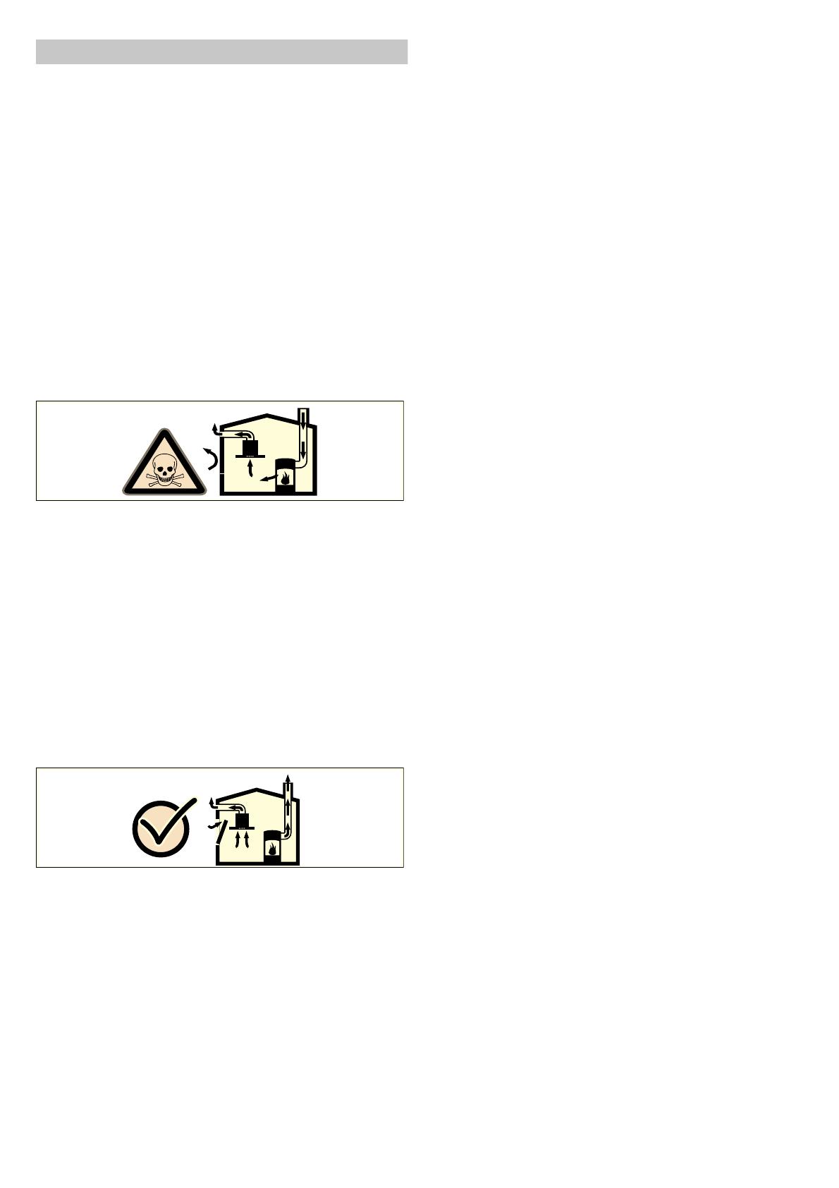
Danger of death!
Risk of poisoning from flue gases that are drawn back in.
Always ensure adequate fresh air in the room if the appliance is
being operated in exhaust air mode at the same time as room
air-dependent heat-producing appliance is being operated.
Room air-dependent heat-producing appliances (e.g. gas, oil,
wood or coal-operated heaters, continuous flow heaters or water
heaters) obtain combustion air from the room in which they are
installed and discharge the exhaust gases into the open air
through an exhaust gas system (e.g. a chimney).
In combination with an activated vapour extractor hood, room air
is extracted from the kitchen and neighbouring rooms - a partial
vacuum is produced if not enough fresh air is supplied. Toxic
gases from the chimney or the extraction shaft are sucked back
into the living space.
■ Adequate incoming air must therefore always be ensured.
■ An incoming/exhaust air wall box alone will not ensure
compliance with the limit.
Safe operation is possible only when the partial vacuum in the
place where the heat-producing appliance is installed does not
exceed 4 Pa (0.04 mbar). This can be achieved when the air
needed for combustion is able to enter through openings that
cannot be sealed, for example in doors, windows, incoming/
exhaust air wall boxes or by other technical means.
In any case, consult your responsible Master Chimney Sweep.
He is able to assess the house's entire ventilation setup and will
suggest the suitable ventilation measures to you.
Unrestricted operation is possible if the vapour extractor hood is
operated exclusively in the circulating-air mode.
Risk of death!
Risk of poisoning from flue gases that are drawn back in. The
exhaust air must not be conveyed into a functioning smoke or
exhaust gas flue or into a shaft which is used to ventilate
installation rooms that contain heating appliances. If the exhaust
air is to be conveyed into a non-functioning smoke or exhaust
gas flue, you must obtain the consent of the heating engineer
responsible.
Danger of suffocation!
Packaging material is dangerous to children. Never allow
children to play with packaging material.
Risk of electric shock!
Components inside the appliance may have sharp edges. These
may damage the connecting cable. Do not kink or pinch the
connecting cable during installation.
Risk of electric shock!
It must always be possible to disconnect the appliance from the
electricity supply. The appliance must only be connected to a
protective contact socket which has been correctly installed. If
the plug is no longer accessible following installation of the
appliance, or a fixed connection is required, an all-pole isolating
switch must be present on the installation side with a contact
gap of at least 3 mm. The fixed connection must only be
installed by an electrician.
Risk of fire!
Grease deposits in the grease filter may catch fire. The specified
safety distances must be observed in order to prevent an
accumulation of heat. Observe the specifications for your
cooking appliance. If gas burners and electric hotplates are
operated together, the largest specified distance applies.
Risk of fire!
Grease deposits in the grease filter may catch fire. Never work
with naked flames close to the appliance (e.g. flambéing). Do
not install the appliance near a heat-producing appliance for
solid fuel (e.g. wood or coal) unless a closed, non-removable
cover is available. There must be no flying sparks.
Risk of injury!
Components inside the appliance may have sharp edges. Wear
protective gloves.
Risk of injury!
The appliance may fall down if it has not been properly fastened
in place. All fastening components must be fixed firmly and
securely.
Risk of injury!
The appliance is heavy. To move the appliance, 2 people are
required. Use only suitable tools and equipment.
Risk of injury!
Changes to the electrical or mechanical assembly are
dangerous and may lead to malfunctions. Do not make any
changes to the electrical or mechanical assembly.


