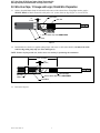
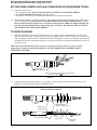
3M Cold Shrink QT-II Outdoor Termination Kit 7654-S-HSG-4, LC, Wire Over Tape Shield, 5-25/28 kV, Insulation OD 0.83-1.53 in, 1/kit Operating instructions
- Type
- Operating instructions
This manual is also suitable for
- Cold Shrink QT-II Outdoor Termination Kit 7652-S-HSG-4, LC, Wire Over Tape Shield, 5-25/28 kV, Insulation OD 0.64-1.08 in, 1/kit
- Cold Shrink QT-II Outdoor Termination Kit 7653-S-HSG-4, 5-25/28 kV, Insulation OD 0.72-1.29 in, 1/kit
- Cold Shrink QT-II Outdoor Termination Kit 7655-S-HSG-4, LC, Wire Over Tape Shield, 5-25/28 kV, Insulation OD 1.05-1.80 in, 1/kit
- Cold Shrink QT-II Outdoor Termination Kit 7656-S-HSG-4, 5-25/28 kV, Insulation OD 1.53-2.32 in, 1/kit
3M Cold Shrink QT-II Outdoor Termination Kit 7654-S-HSG-4, LC, Wire Over Tape Shield, 5-25/28 kV, Insulation OD 0.83-1.53 in, 1/kit is a reliable solution for terminating shielded power cables. It is designed to provide electrical insulation and mechanical protection for the cable termination, ensuring a secure and long-lasting connection. The kit includes a high-amperity ground braid and a constant force spring, which work together to provide a high-quality ground connection and prevent the termination from loosening over time.
3M Cold Shrink QT-II Outdoor Termination Kit 7654-S-HSG-4, LC, Wire Over Tape Shield, 5-25/28 kV, Insulation OD 0.83-1.53 in, 1/kit is a reliable solution for terminating shielded power cables. It is designed to provide electrical insulation and mechanical protection for the cable termination, ensuring a secure and long-lasting connection. The kit includes a high-amperity ground braid and a constant force spring, which work together to provide a high-quality ground connection and prevent the termination from loosening over time.


-
 1
1
-
 2
2
-
 3
3
-
 4
4
-
 5
5
-
 6
6
-
 7
7
-
 8
8
-
 9
9
-
 10
10
-
 11
11
-
 12
12


3M Cold Shrink QT-II Outdoor Termination Kit 7654-S-HSG-4, LC, Wire Over Tape Shield, 5-25/28 kV, Insulation OD 0.83-1.53 in, 1/kit Operating instructions
- Type
- Operating instructions
- This manual is also suitable for
-
- Cold Shrink QT-II Outdoor Termination Kit 7652-S-HSG-4, LC, Wire Over Tape Shield, 5-25/28 kV, Insulation OD 0.64-1.08 in, 1/kit
- Cold Shrink QT-II Outdoor Termination Kit 7653-S-HSG-4, 5-25/28 kV, Insulation OD 0.72-1.29 in, 1/kit
- Cold Shrink QT-II Outdoor Termination Kit 7655-S-HSG-4, LC, Wire Over Tape Shield, 5-25/28 kV, Insulation OD 1.05-1.80 in, 1/kit
- Cold Shrink QT-II Outdoor Termination Kit 7656-S-HSG-4, 5-25/28 kV, Insulation OD 1.53-2.32 in, 1/kit
3M Cold Shrink QT-II Outdoor Termination Kit 7654-S-HSG-4, LC, Wire Over Tape Shield, 5-25/28 kV, Insulation OD 0.83-1.53 in, 1/kit is a reliable solution for terminating shielded power cables. It is designed to provide electrical insulation and mechanical protection for the cable termination, ensuring a secure and long-lasting connection. The kit includes a high-amperity ground braid and a constant force spring, which work together to provide a high-quality ground connection and prevent the termination from loosening over time.
Ask a question and I''ll find the answer in the document
Finding information in a document is now easier with AI
Related papers
-
3M Cold Shrink QT-III 3/C Termination Kit 7620-S-2-3-RJS, Tape/Wire/UniShield®, 3.3-8.7 kV, Insulation OD 0.33-0.50 in, 3/kit Operating instructions
-
-
-
-
-
-
-
-
-
Other documents
-
Ewent EW9000 Datasheet
-
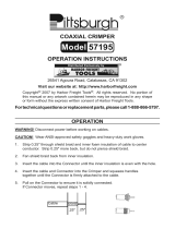 Pittsburgh Item 57195 Owner's manual
-
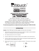 Pittsburgh Coaxial Cable Compression Tool Owner's manual
-
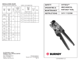 Burndy Y122CMR Installation guide
-
 RIGPOWER HP20 Installation guide
-
Catamount TT-14-30-0-L Specification
-
 Burndy Y1MRTC Installation guide
-
Southwire 64168845 Specification
-
National Instruments MID-7654 User manual
-
Hubbell IS-200TW Installation guide


