Page is loading ...

R5976427
Installation Manual

CYCLOPS (2004-01) R5976427
R5976427, Current Version
Title:
CYCLOPS Installation Manual
ID-no.: R5976427
Date: 2003-12
main issue update
chapter 1
chapter 2
chapter 3
chapter 4
chapter 5
chapter 6
chapter 7
chapter 8
new: The corresponding chapters are new or completely revised.
corr.: Passages of the corresponding chapter were corrected; see modification bars.
add.: Passages of the corresponding chapter were added; see modification bars.
Document History
Modifications which result in a new version are indicated by a vertical bar.
Keep this sheet!

CYCLOPS (2004-01) R5976427
Trademarks
Brand and product names mentioned in this manual may be trademarks, registered trademarks or
copyrights of their respective holders. All brand and product names mentioned in this manual
serve as comments or examples and are not to be understood as advertising for the products or
their manufacturers.
Copyright © 2002, 2003 by Barco Control Rooms GmbH
Die Weitergabe sowie die Vervielfältigung aller Unterlagen, die von uns überlassen werden, deren
Verwertung und Mitteilung ihres Inhaltes an Dritte ist nicht gestattet, soweit dies nicht
ausdrücklich zugestanden ist. Urheberrechte, insbesondere auch solche an Software, werden nur
insoweit übertragen, als es für die Erreichung des speziellen Vertragszwecks erforderlich ist.
Zuwiderhandlungen können zu Schadensersatz verpflichten. Alle Rechte aus der Erteilung eines
Patents oder der Eintragung eines Gebrauchsmusters verbleiben bei uns.
Copyright © 2002, 2003 by Barco Control Rooms GmbH
All rights reserved. No part of this document may be copied, reproduced or translated. It shall not
otherwise be recorded, transmitted or stored in a retrieval system without the prior written consent
of the Barco Control Rooms GmbH.
Guarantee and Compensation
Barco Control Rooms GmbH provides a guarantee relating to perfect manufacturing as part of the
legally stipulated terms of guarantee. On receipt, the purchaser must immediately inspect all
delivered goods for damage incurred during transport, as well as for material and manufacturing
faults. Barco Control Rooms GmbH must be informed immediately in writing of any complaints.
The period of guarantee begins on the date of transfer of risks, in the case of special systems and
software on the date of commissioning, at the latest 30 days after the transfer of risks. In the event
of justified notice of complaint, Barco Control Rooms GmbH can repair the fault or provide a
replacement at its own discretion within an appropriate period. If this measure proves to be
impossible or unsuccessful, the purchaser can demand a reduction in the purchase price or
cancellation of the contract (redhibition). All other claims, in particular those relating to
compensation for direct or indirect damage, and also damage attributed to the operation of
software as well as to other services provided by Barco Control Rooms GmbH, being a component
of the system or independent services, will be deemed invalid provided the damage is not proven
to be attributed to the absence of properties guaranteed in writing or due to the intent or gross
negligence on the part of Barco Control Rooms GmbH.
If the purchaser or a third party carries out modifications or repairs on good delivered by Barco
Control Rooms GmbH, or if the goods are handled incorrectly, in particular if the systems are
commissioned or operated incorrectly or if, after the transfer of risks, the goods are subject to
influences not agreed upon in the contract, all guarantee claims of the purchaser will be rendered
invalid. Not included in the guarantee coverage are system failures which are attributed to
programs or special electronic circuitry provided by the purchaser, e. g. interfaces. Normal wear as
well as normal maintenance are not subject to the guarantee provided by Barco Control Rooms
GmbH either.
The environmental conditions as well as the servicing and maintenance regulations specified in
this manual must be complied with by the customer.


CYCLOPS (2004-01) R5976427
Contents
1 Introduction.................................................................................................................................. 1-1
1.1 Styles And Symbols ............................................................................................................ 1-1
1.2 How this manual is organized ............................................................................................. 1-1
2 Overview...................................................................................................................................... 2-1
2.1 Mechanical setup................................................................................................................. 2-2
2.2 Stitching of the screens ....................................................................................................... 2-2
2.3 Installation and adjustment of the H
ELIOS projector........................................................... 2-2
2.4 Assembling of the trim........................................................................................................ 2-2
2.5 Shielding of the structure .................................................................................................... 2-2
3 Basic information......................................................................................................................... 3-1
3.1 Overview ............................................................................................................................. 3-2
3.2 Nomenclature ...................................................................................................................... 3-3
4 Setup............................................................................................................................................. 4-1
4.1 Assembling the rear part of the structure ............................................................................ 4-2
4.1.1 Assy 1 ......................................................................................................................... 4-2
4.1.2 Assy 2 ......................................................................................................................... 4-2
4.1.3 Assy 3 ......................................................................................................................... 4-2
4.1.4 Assy 4 ......................................................................................................................... 4-3
4.1.5 Assy5 .......................................................................................................................... 4-4
4.2 Assembling the screen supporting structure ....................................................................... 4-5
4.2.1 Assy 6 ......................................................................................................................... 4-5
4.2.2 Assy 7 ......................................................................................................................... 4-6
4.2.3 Assy 8 ......................................................................................................................... 4-6
4.2.4 Assy 9 ......................................................................................................................... 4-7
4.2.5 Assy 10 ....................................................................................................................... 4-8
4.2.6 Assy 11 ..................................................................................................................... 4-10
4.2.7 Assy12 ...................................................................................................................... 4-11
4.2.8 Assy 13 ..................................................................................................................... 4-12
4.3 Installing the second row...................................................................................................4-13
4.3.1 Assy14 ...................................................................................................................... 4-13
4.3.2 Assy15 ...................................................................................................................... 4-14
4.3.3 Assy16 ...................................................................................................................... 4-15
4.4 Connection of the projection unit with the screen frame .................................................. 4-15
4.4.1 Assy17 ...................................................................................................................... 4-15
4.5 Reinforcement of the structure.......................................................................................... 4-16
4.6 Installation of mirror ......................................................................................................... 4-18
4.7 Assembling the stitch plates.............................................................................................. 4-19
4.7.1 Horizontal stitch plates ............................................................................................. 4-19
4.7.2 Vertical stitch plates ................................................................................................. 4-20

CYCLOPS (2004-01) R5976427
4.8 Assembling the HELIOS Projector on its support .............................................................. 4-21
4.8.1 Assy 20 ..................................................................................................................... 4-22
4.8.2 Assy 22 ..................................................................................................................... 4-24
4.8.3 Installation of the power strip................................................................................... 4-25
4.8.4 Assy 23 ..................................................................................................................... 4-26
4.8.5 Assy 24: Stitching of the screens.............................................................................. 4-26
4.8.6 Assembling the trim.................................................................................................. 4-29
4.8.7 Assembling of the design trim..................................................................................4-32
5 Optical Adjustment ...................................................................................................................... 5-1
5.1 General ................................................................................................................................ 5-2
5.1.1 Nomenclature..............................................................................................................5-2
5.1.2 Focus Adjustment .......................................................................................................5-3
5.1.3 Distortions................................................................................................................... 5-4
5.1.4 Vertical Trapezoid ...................................................................................................... 5-4
5.1.5 Horizontal Trapezoid.................................................................................................. 5-5
5.1.6 Rotation....................................................................................................................... 5-6
6 Closing the structure .................................................................................................................... 6-1
7 Hotline.......................................................................................................................................... 7-1
7.1 Addresses............................................................................................................................. 7-2

1 Introd uction

1.1 Styles And Symbols
The typographic styles and the symbols used in this document have the following meaning:
Arial bold
Labels, menus and buttons are printed in the Arial bold font.
Condensed
Links to both other chapters of this manual and to sites in the Internet are printed condensed. In the
on-line version of this manual all hyperlinks appear
teal.
Courier
Names of files and parts from programs are printed in the Courier font.
Courier bold
Inputs you are supposed to do from the keyboard are printed in Courier bold font.
⊗
Within a piece of programming code this arrow marks a line, that must be
made up in two lines, though meant to be one line.
This arrow marks tips and notes.
If you do not heed instructions indicated by this symbol there is a risk of
damage to the equipment!
If you do not heed instructions indicated by this symbol there is a risk of
electrical shock and danger to personal health!

1.2 How th is manual is organized
This manual is divided into 7 chapters.
Introduction
explains the structure of the manual itself and the used typographic styles and symbols.
Overview
Outlines the contents of the manual
Basic Information
Explains the fundamentals about setup
Setup
Describes the various actions for setup step by step
Optical Adjustement
Shows how to adjust the projector within the structure
Closing the structure
Refers to assembling the optional light shields
Hotline
lists the addresses to contact if any problems occur.
Numbering
Chapters, pages, figures and tables are numbered separately. Chapters are indicated by a »point
syntax«, e. g.
4.2.3, pages by a »dash syntax«, e. g. 2-1, figures are consecutively numbered.

2 Overv iew
This manual describes the installation of the modular rear projection system CYCLOPS of BARCO.
It comprises the mechanical setup, stitching of the screens, and installation and adjustment of the
HELIOS projector as well as assembling an optional design trim and optional light shields.

CYCLOPS (2004-01) R5976427 2-2
2.1 Mecha nical setup
The setup of the structure is similar to the setup of Atlas systems: The profiles are assembled by
means of aluminum corners and hammer bolts. If an aluminum corners is not positioned concisely
on the end of a profile, then its exact position is determined using a jig.
2.2 Stitchin g of the screens
As with Atlas, the screens are stitched using stitch border plates. Due to the size of the screens, at
least 3 persons are required, two persons to hold the screen, and the third person to do the
stitching.
2.3 Installa tion and adjustment of the
HELIOS projector
The projector incorporated in
CYCLOPS is the HELIOS projector. For this field of application, a
special support has been design with provides also adjustment facilities. Cabling and operation of
the projector is as usual.
2.4 Assem bling of the trim
The trim comprises standard trim borders and an optional design trim. The standard trim borders
have to be assembled in order to avoid incident light.
The design trim optically closes the gap between the screen borders and the enclosure with a
beautifully designed black aluminum frame.
The design frame is attached by means of a self-adhesive velcro fastening tape to the standard trim
frame, which itself is clipped to the profile structure.
2.5 Shieldi ng of the structure
The structure can be completed with black metal sheets as light shields. Shielding the structure is
optionally available as full shielding (incl. support) or as a standard shielding.

CYCLOPS (2004-01) R5976427 3-1
3 Basic information
This section gives an overview about the profiles and the way to set up the system

CYCLOPS (2004-01) R5976427 3-2
3.1 Overvi ew
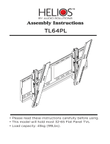
The following sketch and table give an overview about position and length of profiles.
View 1
View
2
R823982
R823982
R816005
R815393
R815393
R815394
R815394
R816009
R816009
R815392
R815392
R816007
R810237
R815893
R815391
R815391
R815391
R815892
R815391
R815391
R815391
X
XX
X
X
X
X
X
R816005
R815892
X
X
X
X
X
X
AB
C
View 1
Figure 1
definition of views
Figure 2
profiles and their position
Profile Length quantity
R816009, with thread on one side 1443.4mm 4*columns
R815394 707.6mm 4*columns
R815393 797.6mm 4*columns
R815391 1290mm columns * 10
R810237, with thread on one side 1200mm 2*columns
R823982 462.35mm 4*columns
R816005 507.35mm 4*columns
R815893 1508.8mm (columns-1) + 2
R815892 1943.8 2*columns
R816007 243mm 2*columns
R824541 563.5mm (4 + 4*rows)*(columns –1)

CYCLOPS (2004-01) R5976427 3-3
In turns, the horizontal profiles are mounted in between the vertical profiles, covering the vertical
profiles on one side or on both sides. This results in differences in length of 45mm (cross-section
of one profile) or of 90mm.
Due to the positions of aluminum corners, the following jigs are required:
Jig Length to set to be used on profile
Jig 1 495mm R816009
jig 2 251.6mm R812037
jig 3 326.75mm 815892
jig 4 404.5mm R815392
jig 5 243.4mm R824233 (second row)
Look at the following sketch to see how to position an aluminum corner by means of a jig:
len
g
th of the
j
i
g
alu corner
jig
profile
Figure 3
how to attach a jig
Position the profile close to the distance angle of the jig.
Attach the aluminum corner by means of hammer bolts
3.2 Nomen clature
Please have a look on the sketch for the various areas and views:
Cut A-B is the rear part of the system, seen from front (view 2)
Cut B-C is the mid part of the system, seen from front (view 2).
Left, right is also defined as seen from front (view 2).

CYCLOPS (2004-01) R5976427 4-1
4 Setup
The following chapter describes the mechanical set up step by step

CYCLOPS (2004-01) R5976427 4-2
4.1 Assem bling the rear part of the structure
The profiles R816009 are the vertical “feet profiles” of the rear part. Therefore they have a thread
on one side to screw in the adjustable feet.
R823982
R823982
R816005
R815393
R815393
R815394
R815394
R816009
Asse
m
blies 1 to 5
R816009
R815392
R815392
R816007
R810237
R815893
R815391
R815391
R815391
R815892
R815391
R815391
R815391
X
XX
X
X
X
X
X
R816005
R815892
X
X
X
X
X
X
AB
C
Figure 4
start of setup
4.1.1 Assy 1
Attach the jig 1 to the profile R816009 on the side without thread.
Fix an aluminum corner
R816009
thread
Jig 1
Figure 5
jig 1 on R816009
This assembly has to be made 4 times for each column
4.1.2 Assy 2
Attach aluminum corners at both ends of profile R815394
R815394
Figure 6
attaching aluminum corners
This assembly has to be made two times for each column. Position the aluminum corners precisely
at the end of the profile!
4.1.3 Assy 3
Connect two assy 1 by means of one assy 2 each.
R816009
R816009
thread
thread
R815394
Figure 7
assembling assy 3

CYCLOPS (2004-01) R5976427 4-3
This assembly has to be made two times for each column. Take care that the profiles connections
are completely closed!
Attach one profile R815394 to each of these assemblies:
R816009
R816009
thread
thread
R815394
R815394
Figure 8
assy 3, second step
Screw in the adjustable feet on all of the four profiles R816009
ajdustable feet, 65mm
R815394
R815394
R816009
R816009
XX
X
X
Figure 9
assy 3, third step
Attach the aluminum corners to the profile R815393
R815393
45mm
45mm
Figure 10
assy 3, forth step
No jig is needed to realize the distance of 45mm of the aluminum corners from the left end /from
the right end. Make use of another profile (cross-section of profile = 45mm)!
Attach R815393 to the assembly 3a:
R815393
R815394
R815394
R816009
R816009
XX
X
X
X
X
Figure 11
completing of assy 3
Per column, two assy 3 are required. These are the not screen supporting side parts of the system.
The connection of the two side parts are made via the horizontal profiles R815391 (assy 4) on
each position marked with an X
4.1.4 Assy 4
Proceed as follows do connect the assembly 4:
Take one of the side parts assy 3 and attach the profiles R815391 to it on the marked positions.
The attachment is done by means of 2 or 3 aluminum corners, respectively, in order to get a rigid
structure, see the following pictures:

CYCLOPS (2004-01) R5976427 4-4
Figure 12
aluminum corners for a rigid structure
Figure 13
aluminum corners for a rigid structure
4.1.5 Assy5
Attach the second side part assy3 to the 6 profiles R815391 (mind the side of the feet!) and add
also aluminum corners to enforce the structure. Now assembly 5 is finished. Put it on its feet.
Figure 14
aluminum corners for a rigid structure
Figure 15
aluminum corners for a rigid structure
The following sketch shows the two cuts A and B of the resulting assembly 5:
R815393
R815393
R815394
R815394
R815394
R815394
R816009
R816009
R815391
R815391
X
X
X
X
X
X
A
R816005
R815393 R815393
R815394 R81539
4
R815394 R815394
R816009
R816009
R815391
R815391
XX
X
X
X
X
X
B
Figure 16
cut A of assy 5
Figure 17
cut B of assy 5
Put a level on the structure and adjust the feet:

CYCLOPS (2004-01) R5976427 4-5
Figure 18
leveling the structure
Figure 19
adjusting the feet
4.2 Assem bling the screen supporting structure
R823982
R823982
R816005 R816005
Assemblies 6 to 8
R823982
R823982
R816005R816005
R815892
R815892
R810237
R810237
R815893
R815893
R815391
R815391
XX
X
X
X
X
X
X
C
Figure 20
screen supporting structure
4.2.1 Assy 6
Attach the jig 2 to the profile R810237 on the side without thread.
Fix an aluminum corner.
R810237
thread
Jig 2
Figure 21
jig 2 on profile R810237
This assembly has to be made 2 times for each column

CYCLOPS (2004-01) R5976427 4-6
The profiles R815391 have to be attached between the two profiles R810237. Therefore one of
R815391 has to be assembled with an aluminum corner at both ends:
R815391
Figure 22
attaching aluminum corners
This assembly has to be made once per column.
To complete the assy 6, attach the profiles and screw in the adjustable feet:
R810237
R810237
R815391
R815391
Figure 23
assembling assy 6
Per column, one assy 6 is required.
4.2.2 Assy 7
To connect the screen supporting structure to the rear structure, the profiles R823982 are used. On
both ends of a profile R823982 two aluminum corners have to be attached, one for connecting
R823982 to the vertical profiles R810237 and R816009, the other to attach R823982 to the
horizontal profile R815391.
Figure 24
assy 7: attaching aluminum corners
Figure 25
assy 7 completed
Assy 7 has to be made twice per column.
4.2.3 Assy 8
Assy 8 results from connecting assy 5 and assy 6 by means of assy 7.
Attach Assy 7 to the leveled assy 6
/