Thermador HMWB30WS Installation guide

Type
Installation guide

This manual is also suitable for

THERMADOR.COM
Installation
INSTRUCTIONS
Thermador Masterpiece
®
Wall Hoods
THERMADOR.COM
Installation
INSTRUCTIONS
Thermador
Masterpiece
®
Wall Hoods
Table of Contents (English) ................................................................... 3
Table de Matières (Français) ................................................................. 22
Índice de Capítulos (Español)................................................................ 41
Models |
Modèles |
Modelos:
HMWB30WS
HMWB361WS
HMWB36WS
HMWB481WS
Installation Instructions English | 3 |
Table of
Contents
Safety ................................................................................. 4
Important Safety Instructions ..................................... 4
Advance Planning .............................................................. 7
Before You Begin ........................................................ 7
General Information ................................................... 8
Installation Preparation...................................................... 9
Installation Considerations ......................................... 9
Electrical Requirements .............................................. 10

Hood Transition .......................................................... 12
Installation Instructions....................................................... 13
Wall Installation ........................................................... 14
Cabinet Installation ..................................................... 15
Electrical Connection .................................................. 16
Remote Control Installation (optional)........................ 17
Chimney Extension Installation (optional)................... 18
Recirculating Kit (optional).......................................... 20
Installer Checklist and Service ........................................... 21
Installer Checklist ........................................................ 21
Before Calling Service ................................................ 21
Product Data Rating Plate .......................................... 21
Safety
Definitions
WARNING
This indicates that death or serious injuries may occur as a
result of non-observance of this warning.
CAUTION
This indicates that minor or moderate injuries may occur
as a result of non-observance of this warning.
NOTICE: This indicates that damage to the appliance or
property may occur as a result of non-compliance with this
advisory.
Note: This alerts you to important information and/or tips.
This THERMADOR® appliance is made by
BSH Home Appliances Corporation
1901 Main Street, Suite 600
Irvine, CA 92614
Questions?
1-800-735-4328
www.thermador.com
We look forward to hearing from you!
Installation InstructionsEnglish | 4 |
Safety
IMPORTANT SAFETY INSTRUCTIONS
READ AND SAVE THESE INSTRUCTIONS
INSTALLER: Save these instructions for the local electrical
inspector’s use. Please leave these instructions with this
unit for the owner. Show the owner the location of the
circuit breaker or fuse. Mark it for easy reference.
OWNER: Please retain these instructions for future
reference.
WARNING
If the information in this manual is not followed exactly,

personal injury.
WARNING
If the information in this manual is not followed
-
ty damage, personal injury or death.
- 
vapors and liquids in the vicinity of this or any other
apppliance.
- WHAT TO DO IF YOU SMELL GAS
DO NOT try to light any appliance.
DO NOT touch any electrical switch.
DO NOT use any phone in your building.
Immediately call your gas supplier from a
neighbor’s phone. Follow the gas supplier’s
instructions.

department.
- Installation and service must be performed by an
authorized servicer, service agency or the gas supplier.
WARNING
Turn off power circuit at service panel and lock out panel
before wiring this appliance. Requirement: 120 VAC, 60
Hz 15 A. Allow the appliance to cool after the power has
been turned off before servicing the appliance.
WARNING
Automatically Operated Device
To reduce the risk of injury disconnect from power supply
before servicing.
WARNING
TO REDUCE THE RISK OF FIRE, ELECTRIC SHOCK,
OR INJURY TO PERSONS, OBSERVE THE
FOLLOWING:
Use this unit only in the manner intended by the
manufacturer. If you have questions, contact the
manufacturer at the address or telephone number
listed on the back page.
Before servicing or cleaning unit, switch power off at
service panel and lock the service disconnecting
means to prevent power from being switched on
accidentally. When the service disconnecting means
cannot be locked, securely fasten a prominent
warning device, such as a tag, to the service panel.
WARNING
DO NOT repair or replace any part of the appliance

Improper installation, service or maintenance can cause
injury or property damage. Refer to this manual for
guidance. All other servicing should be done by an
authorized servicer.
WARNING
ELECTRICAL SHOCK HAZARD
DO NOT remove connections.
DO NOT use an extension cord.
Failure to follow these instructions can

Installation Instructions English | 5 |
IMPORTANT SAFETY INSTRUCTIONS
READ AND SAVE THESE INSTRUCTIONS
Grounding Instructions
WARNING
Improper grounding can result in a risk of electric shock.
This appliance must be grounded. In the event of an electri-
cal short circuit, grounding reduces the risk of electric shock
by providing an escape wire for the electric current.
Be sure your appliance is properly installed and grounded

and grounding must comply with all applicable codes.
If required by the National Electrical Code (or Canadian
Electrical Code), this appliance must be installed on a sepa-
rate branch circuit.
WARNING
DO NOT use
this appliance with any solid state speed device.
Safety Codes and Standards
This appliance complies with one or more of the following
Standards:
UL 507, The Standard for the Safety of Electric Fans
CSA C22.2 No. 113, Fans and Ventilators
It is the responsibility of the owner and the installer to de-
termine if additional requirements and/or standards apply

CAUTION
Unit is heavy and requires at least two people
or proper equipment to move and install.
Hidden surfaces may have sharp edges. Use
caution when handling the appliance. Failure
to do so may result in property damage or
personal injury.
WARNING
State of California Proposition 65 Warnings:
This product can expose you to chemicals including vinyl
chloride, which is known to the State of California to
cause cancer and birth defects or other reproductive
harm. For more information go to
www.P65Warnings.ca.gov.
Never modify or alter the construction of the appliance.
For example, do not remove panels, wire covers or
brackets/screws.
CAUTION
For general ventilating use only. DO NOT use to exhaust
hazardous or explosive materials and vapors.
WARNING


Remove all tape and packaging before using the
appliance. Destroy the packaging after install. Never allow
children to play with packaging material.
WARNING
TO REDUCE THE RISK OF FIRE, ELECTRIC SHOCK,
OR INJURY TO PERSONS, OBSERVE THE
FOLLOWING:
Installation work and electrical wiring must be done


construction.


fuel burning equipment to prevent back drafting.
Follow the heating equipment manufacturer’s
guideline and safety standards such as those
published by the National Fire Protection
Association (NFPA), and the American Society for
Heating, Refrigeration and Air Conditioning
Engineers (ASHRAE), and the local code authorities.
When cutting or drilling into wall or ceiling, do not
damage electrical wiring and other hidden utilities.
Ducted fans must always be vented to the outdoors.
Installation InstructionsEnglish | 6 |
IMPORTANT SAFETY INSTRUCTIONS
READ AND SAVE THESE INSTRUCTIONS
WARNING
TO REDUCE THE RISK OF A RANGE TOP GREASE
FIRE:
Never leave surface units unattended at high
settings.
Boilovers cause smoking and greasy spillovers that
may ignite. Heat oils slowly on low or medium
settings.
Always turn hood ON when cooking at high heat

Cherries Jubilee, Peppercorn Beef Flambe).
Clean ventilating fans frequently. Grease should

Use proper pan size. Always use cookware
appropriate for the size of the surface element.
WARNING
TO REDUCE THE RISK OF INJURY TO PERSONS IN
THE EVENT OF A RANGE TOP GREASE FIRE,
OBSERVE THE FOLLOWING:
a

sheet, or metal tray, then turn off the burner. BE

go out immediately, EVACUATE AND CALL THE
FIRE DEPARTMENT.
NEVER PICK UP A FLAMING PAN - you may get
burned.
DO NOT USE WATER, including wet dishcloths or
towels - a violent steam explosion will result.
Use an extinguisher ONLY if:
a) You know you have a class ABC extinguisher,
and you already know how to operate it.
b) 
it started.
c) 
d) 
a
Based on “Kitchen Fire Safety Tips” published by NFPA.
Installation Instructions English | 7 |
Advance Planning
Before You Begin
CAUTION
Before installing, turn power OFF at the service panel.
Lock service panel to prevent power from being turned
ON accidentally.
Parts Included
Hood assembly (lamps and blower
already installed)
10” Metal transition with backdraft
damper

Fastener assortment*
* Hardware provided is for mounting through standard
thickness drywall or plaster into wood studs. Installers
are responsible to provide hardware for other types of
mounting situations.
Tools and Parts Needed
Ducting as needed (refer to Equivalent Duct Lengths
for Commonly Used Transitions Table)
Aluminum tape (DO NOT use duct tape)
1/2’’ (13 mm) Conduit if required (follow local codes)
1’’ (25.4 mm) Strain relief
Ducting as needed
Blower
Flat head and Phillips screwdrivers
Drill with 3/16’’ (4.76 mm) drill bit
Circular saw or jigsaw
3/8’’ (9.52 mm) nut driver or socket and ratchet
Wire stripper
Protective work gloves
IMPORTANT: DO NOT throw away any packaging until
appliance is fully installed.
Optional accessories available for separate
purchase.
Refer to www.thermador.com for more details.
DCT3016W – 16” tall Duct Cover Kit 30”
DCT3616W – 16” tall Duct Cover Kit 36”
DCT4816W – 16” tall Duct Cover Kit 48”
DC30MTW – Telescopic Duct Cover Extension Kit 30”
DC36MTW – Telescopic Duct Cover Extension Kit 36”
DC48MTW – Telescopic Duct Cover Extension Kit 48”
RECHMWB30 – Recirculating Kit 30”
RECHMWB36 – Recirculating Kit 36”
CHFILT3036 – Charcoal Filter Replacement Kit
REMCPW – Built-In Remote Control Accessory
Installation InstructionsEnglish | 8 |
General Information
Overall Dimensions
HMWB30WS, HMWB361WS, HMWB36WS & HMWB481WS
This model series is 23
4
16’ (590 mm) in depth and feature
brushed stainless-steel canopy with LED lights.
inches (mm)
7
11"
(280)
4
5
/
16
"
(110)
10" (254)
6"
(152.5)
12"
(305)
23
4
/
16
" (590)
30" (762)
36" (914)
48" (1219)
10" (254)
NOTE: Transition is centered horizontally.
Installation Instructions English | 9 |
Installation Preparation
Installation Considerations
Clearances and requirements
Hood installation height above a cooktop, rangetop or
range can vary. To obtain the necessary installation height
above a cooktop, rangetop or range, consult the applian-
ce’s installation manual.
11"
(280)
4
5
/
16
"
(110)
30" (762) min over a gas cooktop
30" (762) min over an electric cooktop
Hood Width
The hood width should be no less than the width of the
cooking surface. For proper performance, the housing
must cover the entire cooking surface. Where space is
not restricted, a wider hood can be used to increase
capture area.
For proper performance, the hood must be centered
horizontally above the cooking surface.
Distance From Cooking Surface
For gas cooktop & range installations: Mount the hood
so the bottom is at least 30” (76.2 cm) above the cooking
surface.
For electric/induction cooktop & range installations:
Mount the hood so the bottom is at least 30” (76.2 cm)
above the cooking surface.
NOTICE: The hood could incur some damage from heat
if a THERMADOR MASTERPIECE
®
series cooktop is opera-
ted with multiple burners at high settings under a hood that
is installed at minimum clearances.
Unit Weight
This vent hood is heavy. Adequate structure and support
must be provided in all types of installations.
When calculating the load for the housing support
system, be sure to consider the weight of the
ventilation unit.
Unit Weight
30’’ (76 cm) 40.3 lb (18.3 kg)
36’’ (91 cm) Single blower 42.5 lb (19.3 kg)
36’’ (91 cm) Dual blower 54.6 lb (24.8 kg)
48’’ (122 cm) 65.9 lb (29.9 kg)
IMPORTANT:
The supplied weights address only the ventilation unit and
blower. Installer must account for weight of any materials
of construction when calculating the total dead weight
load of installation, including but not limited to: wall, tile,
-
ly incorporated architectural and structural items. It is the
responsibility of the owner and the installer to determine if

installations.
Wall Framing
Due to the weight of the hood, make sure the wood moun-
ting bracket is attached to all available wall studs.
Framing must be fastened together and to ceiling joists to
provide enough structural strength to support the weight of
the hood and internal blower, if applicable.
Wall framing should be, at minimum, made of 2”x 4” lum-
ber. Proper structural support is required to accommodate
the weight of the hood.
Installation InstructionsEnglish | 10 |
Electrical Requirements
The unit requires a 120V AC, 60Hz. 15A branch circuit.
The hood should only be connected to a dedicated circuit
(with ground) that has been installed according to relevant
regulations.
Check your local building codes for proper method of ins-
tallation. In the U.S., if there are no applicable local codes,
this unit should be installed in accordance with the National
Electric Code ANSI/NFPA No. 70, Current Issue. In Canada,
installation must be in accordance with the CAN 1- B149.1
and .2 - Installation Codes for Gas Burning Appliances and/
or local codes.
The appliance must be grounded. In the event of an elec-
trical short circuit, grounding reduces the risk of electric
shock by providing a wire that allows the electric current to
escape.
WARNING
The appliance must be grounded.
Electrical Data on the Data Rating Label
Data, including the model and serial number, is located
on the product data rating label inside the appliance,

Ductwork Preparation
Discharge Direction
The exhaust air is discharged upwards through a duct.
The hood can be mounted only with a vertical discharge.
Ducting Recommendations
Proper performance is dependent upon proper ducting.
Local building codes may require the use of make-up air
systems when using ducted ventilation systems greater than


responsibility of the owner and the installer to determine if

installations.
DO NOT USE FLEXIBLE DUCT; it creates back pressure/
air turbulence and reduces performance. Always use metal
ductwork.
Always install a metal vent cover where the ductwork exits
the house. Hood must be vented to the outside of building
only.
COLD WEATHER installations should have an additional
backdraft damper installed to minimize backward cold air
-
tion of outside temperatures as part of the ductwork. The
damper should be on the cold air side of the thermal break.
The break should be as close as possible to where the duc-
ting enters the heated portion of the house.
MAKE-UP AIR: Local building codes may require the use of
make-up air systems when using ducted ventilation systems


responsibility of the owner and the installer to determine if

installations.
For safety reasons, ducting should vent directly outdoors
(not into an attic, underneath the house, into the garage or
into any enclosed space).
THERMADOR
®
recommends not exceeding 50 equivalent
length (ft) (15.24 m) of duct.
Keep duct runs as short and straight as possible.

Back to back elbows and “S” turns give very poor delivery
and are not recommended.
A short straight length of duct at the inlet of a remote
blower gives the best delivery.
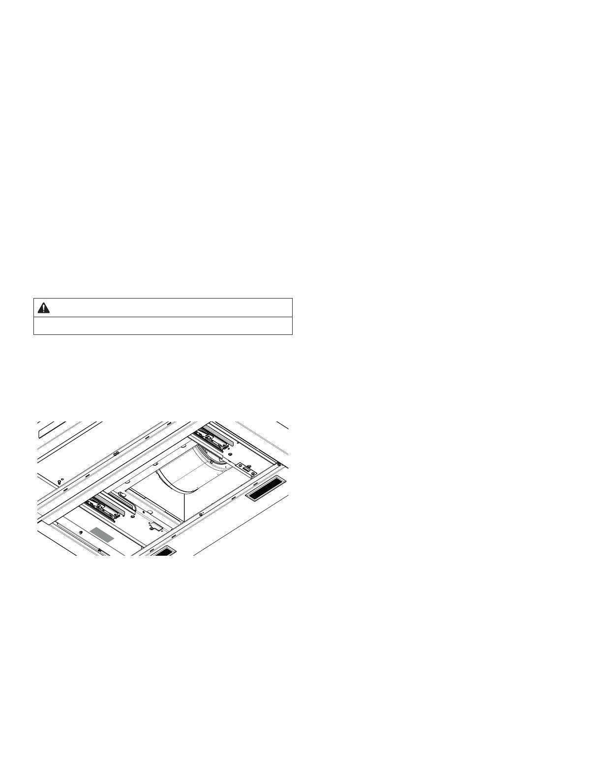
Hoods are supplied with a 10” (254 mm) round transition.
A locally supplied transition is required for other sizes.
Use “Equivalent Duct Lengths for Commonly Used Transi-
tions” on page 11 to compute permissible lengths for duct
runs to outdoors.
Installation Instructions English | 11 |
Equivalent Duct Lengths for Commonly
Used Transitions
Size (in)
Eq uivalent
Length (ft)
Size (in)
Eq uivalent
Length (ft)
61.2
61
0
80.7
10 0.6
" x 10", straight N/A1
" x 10", Center
reverse elbow, right
N/
A2
5
" x 14", straight N/A0.7
" x 10", Left
reverse elbow
N/
A1
5
" x 10", Right
reverse elbow
N/
A2
5
612
62
86
82
10
10 2
65
62
2
5
83
82
2
2
10
10
" x 10",
90° elbow, round
N/A5
2’ long, 3¼" x 10" flexN/A 20
" x 10",
45° elbow, round
N/A15
" x 10", Flat elbowN/A 20
61
810
82
" x 10", Roof jack
and shutter
N/A
65
61
0
NOTE: These commonly used installation parts can be purchased at a
local hardware store. Thermador does not manufacture all these parts.
Round wall cap
Round roof cap
" x 10" to round
90° elbow,
Duct Piece
" x 10" Center
reverse elbow, left
15N/A
Round to 3¼" x 10"
" x 10" to round
Round to 3¼" x 10"
90° elbow,
Duct Piece
Smooth, straight
90° elbow, round
45° elbow, round
Installation InstructionsEnglish | 12 |

A
B
C
F
F
A
B
D
F
C
E
RECIRCULATING MODE VENTING THROUGH THE WALL VENTING THROUGH THE CEILING
A. 10” round transition
B. 10” round duct system
C. Cabinet / Duct cover kit
D. 90° elbow
E. Recirculating kit
F. Installation height:
Gas range MIN: 30” (76.2 cm)
Electric range MIN: 30” (76.2 cm)
NOTE: 
Venting Methods
This hood is factory set for venting through the roof (vertical
discharge) or wall (horizontal discharge). A 10” (254 mm)
round duct system is needed for installation (not included).
NOTE: Flexible duct is not recommended. Flexible
ductwork creates back pressure and air turbulence that
greatly reduce performance.
Vent system can terminate either through the roof or wall.
Always install a metal vent cover where the ductwork exits
the house.
For Non-Vented (recirculating) Installations
If it is not possible to vent cooking fumes and vapors to
the outside, models HMWB30WS and HMWB36WS can
be used in the non-vented (recirculating) version, using the
recirculating kit (sold separately). Fumes and vapors are
recycled through the grid.
See optional accessories section.
Hood Transition
Vertical Discharge Transition
The hood is shipped ready for vertical discharge.
The transition supplied with the hood connects to standard

for vertical discharge.
11"
(280)
6"
(152.5)
CL
4
5
/
16
"
(110)
Assembly of the Transition
A minimum height clearance of 4
5
16’ (110 mm) is needed
above the hood for transition mounting. See “General
Information” on page 6 for overall hood dimensions.
1. Depending on direction of discharge, align mounting
holes at base of transition with the mounting holes on
the top of the hood.
Installation Instructions English | 13 |
2. Fasten transition to hood using four (4)
1
4’ (6 mm)
sheet metal screws included with hood.
3. Seal connection between transition and hood with
aluminum tape. DO NOT use duct tape. Ensure that
the connection is completely sealed.
4. Remove tape holding damper closed.
5. 
screwdriver and a small hammer.
Take care of sharp edges.
6. Install strain relief (not included) into the circular
knockout.
Installation Instructions
Installation
Determine installation height
11"
(280)
4
5
/
16
"
(110)
30" (762) min over a gas cooktop
30" (762) min over an electric cooktop

Accessory 6’’ (152 mm) and/or 12’’ (305 mm) duct covers

for some models (available for purchase separately).
For gas cooktop & range installations: Mount the hood
so the bottom is at least 30” (76.2 cm) above the cooking
surface.
For electric/induction cooktop & range installations:
Mount the hood so the bottom is at least 30” (76.2 cm)
above the cooking surface.
NOTICE: The hood could incur some damage from heat
if a THERMADOR MASTERPIECE
®
series cooktop is opera-
ted with multiple burners at high settings under a hood that
is installed at minimum clearances.
Installation InstructionsEnglish | 14 |
Wall installation
1. Turn power OFF at the service panel. Lock service panel
to prevent power from being turned ON.
2. After the hood installation height has been determined,
draw a horizontal line at a distance above the cooktop
equal to the recommended hood installation height plus
10
4
16’ (260 mm). This line is the mounting location of
the upper mounting screws.
3. Find the centerline of the hood. Draw a vertical line
along this centerline up to the horizontal line drawn
in Step 2.
4. Mark the screw hole locations indicated in the diagram.
Center
Line
AA
B
D
E
B
WALL
C
30” (76.2 cm) 36” (91.4 cm) 48” (121.9 cm)
A
6
15
16” (17.5 cm) 11
4
16” (28.5 cm) 11
4
16” (28.5 cm)
B
10
13
16” (27.5 cm) 10
13
16” (27.5 cm) 10
13
16” (27.5 cm)
C
10
15
16” (27.8 cm) 10
15
16” (27.8 cm) 10
15
16” (27.8 cm)
D
7
3
4” (19.7 cm) 7
3
4” (19.7 cm) 7
3
4” (19.7 cm)
E
13
16” (2 cm)
13
16” (2 cm)
13
16” (2 cm)
5. If drywall is present, cut away enough drywall to expose
2 vertical studs at the indicated holes location. Install
two horizontal supports between two wall studs at the
bottom and upper mounting holes installation location.
6. 
of the studs. Use cleats behind both sides of the support
to secure wall studs.
7. 
View from rear
Mounting
Support
Centerline of
Installation space
IMPORTANT: Framing must be capable of
supporting 100 lbs.
Cleats
8. Cut holes at marked locations for duct and electrical
wiring.
Mounting the hood
1. Drive a mounting screw (from the hardware package)
partway into each center of the narrow neck of the
keyhole slots marked on the wall’s support frame.
2. Install the 2 pieces of the selected screws on the
mountings screws location (see the image). Leave a
1
4’’
(6.4 mm) gap between the wall and the back of the
screw head to slide range hood into place.
1
/
4
"
(6.4)
3. Fix the wiring conduit of the hood.
Installation Instructions English | 15 |
4. Slide the hood back against the wall. Tighten the
mounting screws. Be sure the screw heads are in the
narrow neck of the keyhole slot.
B
A
5. Drive 2 pieces of the selected screws in the lower
security screws location (see the image above).
6. Connect Ductwork to hood.
Cabinet Installation
Turn power OFF at the service panel. Lock service panel
to prevent power from being turned ON.
Cabinet cutouts
1. Use the diagram or the hood as a template and mark
the locations on the cabinet for ductwork, electrical
wiring and keyhole screw slots.
Center
Line
A
A
C
D
E
F
I
G
H
A
B
A
Front face
of the cabinet
Bottom face
of the cabinet
Wall
A
5
4
16” (13.3 cm)
F
3
7
16” (8.7 cm)
B
3
4” (1.9 cm)
G
1
1
2” (4 cm)
C
6
16” (1 cm)
H
1” (2.54 cm)
D
7
1
16” (18 cm)
I
3
16” (.5 cm)
E
2
9
16” (6.5 cm)
For recessed bottom cabinet only
If the cabinets have front, side or back trim, make 2 wood
shims the width of the trim and attach them to the cabinet
bottom recess on both sides.
NOTE: Your cabinet must be able to support at least 88 lb
(40 kg).
Drive a mounting screw (from the hardware package)
partway into each center of the narrow neck of the
keyhole slots marked on the cabinet bottom or the
wall’s support frame.
Install 4 - 4 x 8 mm mounting screws on the mountings
screws location (see the image). Leave a
1
4’ (6.4 mm)
gap between the wall and the back of the screw head
to slide range hood into place.
1
/
4
"
(6.4 mm)
Fix the wiring conduit of the hood.
Slide the hood back against the cabinet. Tighten the
mounting screws. Be sure the screw heads are in the
narrow neck of the keyhole slot.
A
Installation InstructionsEnglish | 16 |
Electrical Connection
WARNING
Electrical Shock Hazard
Disconnect power before servicing.
Replace all parts and panels before operating.
Failure to do so can result in death or electrical shock.
Disconnect power.
Remove terminal box cover.
Remove the knockout in the terminal box cover and
install a UL listed or CSA approved 1/2” strain relief.
C
A
B
A Juction Box
B Knockout
C Juction Box cover
Run home power supply cable through strain relief,
into terminal box.
A
F
C
E
B
D
A. Home power supply cable
B. UL listed or CSA approved
strain relief
C. Black wires
D. UL listed wire connectors
E. White wires
F. Green (or bare) and yellow-green
ground wires
Use UL listed wire connectors and connect black wires
(C) together.
Use UL listed wire connectors and connect white wires
(E) together.
WARNING
Electrical Shock Hazard
Electrically ground blower.
Connect ground wire to green and yellow ground wire
in terminal box. Failure to do so can result in death or
electrical shock.
Connect green (or bare) ground wire from home power
supply to yellow-green ground wire (F) in terminal box
using UL listed wire connectors.
Tighten strain relief screw.
Install terminal box cover.
Reconnect power.
Installation Instructions English | 17 |
Remote Control Installation
(optional)
Before you begin, read these instructions carefully. It is
recommended that the Remote Control be wired to the
hood after the hood is installed.
REMCPW Parts Included
1 – Remote control
1 – 30 ft. extension harness
IMPORTANT: Cutting off a connector to the appliance or
to the extension cable kit will void the warranty.
Remote Control Installation
2. Prepare the wall (or similar surface) cutout for
installation as shown below (view is shown facing wall)
13
5
8
/
"
(346)
2
5
8
/
"
(65)
inches (mm)
3. Access the hood’s wiring. Route the 30 ft. extension
harness through the strain relief to the square mounting
clip until it clicks.
4. Route the 30 ft extension harness through the cutout
and connect the harness to the back of the remote
control bracket.
5. Press the bracket inside the cutout. Drill a ¼’’ (6 mm)
tap hole through the bracket holes into the wall.
Mount the bracket to the wall using the four (4) screws
provided.
6. Hook up the wire harness connector inside the bracket
to the terminal on the back side of the remote control.
Use either terminal.
7. Snap the Remote Control into the bracket.
Installation InstructionsEnglish | 18 |
Chimney Extension Installation
(optional)
On some models, optional duct covers and telescoping

and ceiling in wall mount installations. Chimney extensions

ceilings. Telescoping extensions accommodate 12’ (3.6 m)
ceilings.
Model Duct Cover
Telescopic
Extension
HMWB30WS DCT3016W DC30MTW
HMWB361WS
DCT3616W
DCT3616W
DC36MTW
DC36MTW
HMWB36WS
HMWB481WS DCT4816W DC48MTW
Duct Cover Extension Installation
IMPORTANT NOTE: Secure the Chimney Wall Hood to the
wall before installing the Chimney Extension. See “Moun-
ting the Hood” on page 14 before securing the actual
Extension.
1. Installation of the chimney hood should maintain a
minimum height of 30” (762 mm) from the bottom of
the hood to the cooking surface. To determine
placement of the hood with a Chimney Extension, the
height of the chimney extension must be calculated.
2. From inside of hood, screw the supplied
5
8’ (16 mm)
sheet metal screws through the holes on each side and
along the front into bottom of the extension, as shown
in below. (Screw quantity is dependent on hood size.)
Telescopic Duct Cover Installation
IMPORTANT: Secure the Chimney Hood to the wall after
installing the Extension Mounting Bracket, but before
installing the Telescoping Chimney Extension. See
“Wall Installation” on page 14 before securing the actual
Extension.
Securing the Telescoping Chimney Extension Bracket
1. Ensure that the minimum height of 30” (762 mm) from
the bottom of the hood to the cooking surface will be
maintained.
2. Locate two studs at the mounting location.
inches (mm)
A
B
Max. 61”
(1550)
Min. 31”
(787)
30”
(762)
31”
(787)
11”
(280)
Model A B
30” 12” (305) 30” (762)
36” 12” (305) 36” (914)
48” 12” (305) 48” (1219)
Installation Instructions English | 19 |
3. Mount the duct cover bracket on the top of the ceiling
using (2) 1½’’ (38 mm) screws (provided). Ensure that the
bracket is level.
4. Insert the complete duct cover at an angle and swivel
toward the wall.
5. Carefully pull the top part of the extension upwards.
Screw the left and right sides of the extension to the
mounting bracket with the supplied stainless screws.
6. From inside of hood, screw the supplied 5/8’’ (16 mm)
sheet metal screws through the holes on each side
and along the front into bottom of the extension.
Screw quantity is dependent on hood size.
Installation InstructionsEnglish | 20 |
Recirculating Kit (optional)
When used in recirculation mode, To Reduce the Risk of
Fire and Shock use only conversion kit Models
RECHMWB30 and RECHMWB36.
Model Recirculating Kit
HMWB30WS RECHMWB30
HMWB36WS RECHMWB36
If it is not possible to vent cooking fumes and vapors to
the outside, the hood can be used in the non-vented
(recirculating) version, using the recirculating kit.
Fumes and vapors are recycled through the round grid.
Before installing the recirculation kit
The Installation of the Recirculation kit affects the installa-
tion of the hood, so take into consideration the following
steps.

installing the recirculation kit.

there’s no need to provide cutouts on walls for vertical or
rear air discharge, since there is no need to install any Duct.
NOTE: Check that there is enough clearance and that
minimum height from the countertop to the bottom of the
hood is 30” (76.2 cm).
NOTE: The transition must not be installed, since no duc-
ting is necessary.
Wall Mount Installation

wall:
1. 
tighten completely.
C
C
C
C
2. 
go respectively into Side Slots on top of the hood and

frontward until stops.
3. Tighten the four screws C from inside of the hood.
4. 

hood size).
5. Proceed to install hood as described on Wall Mount
Installation described at the Hood Installation Manual.
Charcoal filter
In the reciruclating mode, the air will be recirculated

and odors.

Cover the grill that protects the suction motor with the

to the pins on the sides of the motor protection grill.


NOTE:
replaced every 4-6 months (depending on hood usage).
  • Page 1 1
  • Page 2 2
  • Page 3 3
  • Page 4 4
  • Page 5 5
  • Page 6 6
  • Page 7 7
  • Page 8 8
  • Page 9 9
  • Page 10 10
  • Page 11 11
  • Page 12 12
  • Page 13 13
  • Page 14 14
  • Page 15 15
  • Page 16 16
  • Page 17 17
  • Page 18 18
  • Page 19 19
  • Page 20 20
  • Page 21 21
  • Page 22 22
  • Page 23 23
  • Page 24 24
  • Page 25 25
  • Page 26 26
  • Page 27 27
  • Page 28 28
  • Page 29 29
  • Page 30 30
  • Page 31 31
  • Page 32 32
  • Page 33 33
  • Page 34 34
  • Page 35 35
  • Page 36 36
  • Page 37 37
  • Page 38 38
  • Page 39 39
  • Page 40 40
  • Page 41 41
  • Page 42 42
  • Page 43 43
  • Page 44 44
  • Page 45 45
  • Page 46 46
  • Page 47 47
  • Page 48 48
  • Page 49 49
  • Page 50 50
  • Page 51 51
  • Page 52 52
  • Page 53 53
  • Page 54 54
  • Page 55 55
  • Page 56 56
  • Page 57 57
  • Page 58 58
  • Page 59 59
  • Page 60 60

Thermador HMWB30WS Installation guide

Type
Installation guide
This manual is also suitable for

Ask a question and I''ll find the answer in the document

Finding information in a document is now easier with AI