
271107 - 271127 - 271137 - 271147 -
271157 - 271167 - 271177 - 271187 -
271207 - 271139 - 271149 - 271159 -
271169 - 271179 - 271189 - 271209 -
271229

Bartscher GmbH
Franz-Kleine-Str. 28
D-33154 Salzkotten
Germany
Phone: +49 5258 971-0
Fax: +49 5258 971-120
Technical Support Hotline: +49 5258 971-197
www.bartscher.com
Version: 1.0
Date of preparation: 2020-10-01
EN

271107 1 / 22
Original instruction manual
1 Safety ............................................................................................................ 2
1.1 Explanation of Signal Words .................................................................... 2
1.2 Safety instructions.................................................................................... 3
1.3 Intended Use ........................................................................................... 5
1.4 Unintended Use ....................................................................................... 5
2 General information ....................................................................................... 6
2.1 Liability and Warranty .............................................................................. 6
2.2 Copyright Protection ................................................................................ 6
2.3 Declaration of Conformity ........................................................................ 6
3 Transport, Packaging and Storage ................................................................ 7
3.1 Delivery Check ......................................................................................... 7
3.2 Packaging ................................................................................................ 7
3.3 Storage .................................................................................................... 7
4 Technical Data ............................................................................................... 8
4.1 Technical Specifications .......................................................................... 8
4.2 List of Components of the Appliance ..................................................... 10
4.3 Functions of the Appliance ..................................................................... 10
5 Installation and operation ............................................................................ 11
5.1 Installation .............................................................................................. 11
5.2 Operation ............................................................................................... 17
6 Cleaning and Maintenance .......................................................................... 18
6.1 Safety Instructions for Cleaning ............................................................. 18
6.2 Cleaning ................................................................................................. 18
6.3 Maintenance .......................................................................................... 19
7 Possible Malfunctions .................................................................................. 20
8 Disposal ....................................................................................................... 20

Safety
2 / 22 271107
EN
Diese Bedienungsa nleitung besc hreibt die Installa tion, Bedienu ng und Wartu ng des Geräts u nd gilt als wic htige Informationsqu elle und N achschlagewer k. Die Kenntnis aller enthaltene n Sicherheitshi nweise und H andlungsanw eisungen schafft die Voraussetz ung für das sich ere und sac hgerechte Ar beiten mit de m Gerät. Darüber hi naus müsse n die für den Ei nsatzbereic h des Geräts gelte nden örtlichen Un fallverhütungs vorschriften und allgemeinen Sicherheitsbesti mmungen eingehalten werden. Diese Bedi enungsanleitung is t Bestandt eil des Produ kts und muss in unmittelbarer N ähe des Geräts für das In¬s tallations-, B edienungs-, Wartungs- und R einigungspers onal jederzeit z ugänglich auf¬b ewahrt werden. W enn das Ger ät an eine dritt e Person
weitergegeben wird, muss die B edienungsanlei tung mit ausgehä ndigt werden.
Read this instruction manual before using and keep it available
at all times!
This instruction manual contains information about installation, operation and
maintenance of the appliance and constitutes an important source of information
and reference guide. The knowledge of all operational and safety instructions
included in this manual is a prerequisite for safe and proper handling of the
appliance. Additionally, accident prevention, occupational health and safety, and
legal regulations in force in the area the appliance is used apply.
Before you start using the appliance, especially before turning it on, read this
instruction manual in order to avoid personal injuries and property damages.
Improper use may cause damage.
This instruction manual forms and integral part of the product and must be stored in
an immediate vicinity of the appliance and be available at all times. The instruction
manual should be transferred together with the appliance.
1 Safety
This appliance has been manufactured in accordance with technical standards
currently in force. However, the appliance may be a source of hazards if used
improperly or contrary to its intended purpose. All persons using the appliance must
consider information included in this instruction manual and observe safety
instructions.
1.1 Explanation of Signal Words
Important safety instructions and warning information are indicated in this
instruction manual with appropriate signal words. You must strictly follow the
instructions, to prevent accidents, personal injuries and property damages.
DANGER!
The signal word DANGER warns against hazards that lead to severe
injuries or death if the hazards are not avoided.

Safety
271107 3 / 22
EN
WARNING!
The signal word WARNING warns against hazards that may lead to
moderate or severe injuries or death if the hazards are not avoided.
CAUTION!
The signal word CAUTION warns against hazards that may lead to
light or moderate injuries if the hazards are not avoided.
, die
IMPORTANT!
The signal word IMPORTANT indicates possible property damages,
which may occur if safety instructions are not observed.
NOTE!
The symbol NOTE indicates subsequent information and guidelines
for the user on usage of the appliance.
1.2 Safety instructions
Electrical Current
• Too high a mains voltage or incorrect installation may cause electric shock.
• The appliance may be connected only if data on the rating plate correspond with
the mains voltage.
• To avoid short-circuit, the appliance should be kept dry.
• If there are malfunctions during operation, disconnect the appliance from the
power supply.
• Do not touch the appliance’s plug with wet hands.
• Never take hold of the appliance if it has fallen into water. Immediately
disconnect the appliance from the power supply.
• Any repairs or housing opening may be carried out by professionals and
relevant workshops only.
• Do not transport the appliance, holding it by the power cord.
• Do not allow the power cord to come into contact with heat sources or sharp
edges.
• Do not bend, pinch nor knot the power cord.

Safety
4 / 22 271107
EN
• Always completely unwind the power cord.
• Never place the appliance or other objects on the power cord.
• Always take hold of the plug to disconnect the appliance from the power supply.
• Check the power cord regularly for damage. Do not use the appliance if the
power cord is damaged. If this cable is damaged, it must be replaced by
customer service or a qualified electrician in order to avoid dangers.
Operating Personnel
• The appliance may only be operated by qualified personnel and trained
specialist personnel.
• This appliance may not be operated by persons (including children) with limited
physical, sensory or mental capabilities, nor by persons with limited experience
and/or limited knowledge.
• Children should be supervised to ensure that they are not playing with or
switching on the appliance.
Improper Use
• Unintended or prohibited use may cause damage to the appliance.
• The appliance may only be used when its technical condition is flawless and
allows for safe operation.
• The appliance may only be used when all connections are executed according
to rules of law in force.
• The appliance may only be used when it is clean.
• Use only original spare parts. Never attempt to repair the appliance on your own.
• Do not introduce any changes in the appliance nor modify it.

Safety
271107 5 / 22
EN
1.3 Intended Use
As described below, every use of the appliance for a purpose differing and/or
diverging from its intended standard use, is prohibited and considered to be an
unintended use.
The following is an intended use:
– Venting and exhausting steams and vapours.
1.4 Unintended Use
An unintended use may lead to personal injuries or property damages caused by
hazardous voltage, fire or high temperature. The appliance may only be used to
perform tasks described in this instruction manual.

General information
6 / 22 271107
EN
2 General information
2.1 Liability and Warranty
All information and instructions in this instruction manual account for legal
regulations in force, current level of technical engineering knowledge as well as our
expertise and experience, developed over the years. If special models or additional
options are ordered, or state-of-the-art technical solutions were implemented, the
actual scope of delivery of the appliance may, in some circumstances, differ from
descriptions and numerous drawings in this instruction manual.
The manufacturer is not liable for any damages nor faults stemming from:
– failure to observe instructions,
– unintended use,
– technical alterations introduced by the user,
– usage of unapproved spare parts.
We reserve the right to introduce technical modifications to the product, intended for
improvement of the appliance and its performance.
2.2 Copyright Protection
This instruction manual, and texts, drawings and images included in it, as well as its
other components are copyright protected. It is prohibited to reproduce this
instruction manual (including its excerpts), in any form and by any means, and to
use and/or transfer its content to third parties without manufacturer’s written
permission. Violation of the above results in obligation to pay compensation. We
reserve the right to claim further damages.
2.3 Declaration of Conformity
The appliance meets the currently applicable standards and guidelines of the
European Union. We confirm the above in the EC Declaration of Conformity. We
may provide relevant Declaration of Conformity upon request.

Transport, Packaging and Storage
271107 7 / 22
EN
3 Transport, Packaging and Storage
3.1 Delivery Check
Immediately upon reception, check the delivery for completeness and possible
shipping damage. In the case of visible transport damage refuse to accept the
appliance or accept it conditionally. Mark and note the scope of damage in shipping
documents/consignment list of the shipping company and lodge a complaint.
Concealed damage must be reported immediately upon its discovery, as
compensation claims may only be filed within applicable time limits.
If you find that parts or accessories missing, please contact our Customer Service
Department.
3.2 Packaging
Do not dispose of the appliance cardboard box. It may be used to store the
appliance when relocating or when shipping the appliance to our service point in the
case of any damages.
The packaging and its elements are made of recyclable materials. Particularly,
these are: plastic films and bags, cardboard box.
When disposing of the packaging, observe applicable domestic regulations.
Recyclable packaging materials should be recycled.
3.3 Storage
Leave the packaging closed until installation of the appliance; observe external
indications concerning method of placing and storage. Store the packaging in the
following conditions only:
– in closed rooms;
– in dry and dust-free surrounding;
– away from aggressive agents;
– in a location protected against sunlight;
– in a location protected against mechanical shocks.
In the case of extended storage (over three months), make sure you check the
condition of the packaging and the parts regularly. If needed, replace the packaging
with a new one.

Technical Data
8 / 22 271107
EN
4 Technical Data
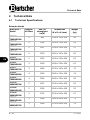
4.1 Technical Specifications
Extractor Hoods
Article No. /
Model
Number
of filters
Max. air
throughput
(m³/h)
Dimensions
W x D x H (mm)
Weight
(kg)
271107
700M-W1000
2
882
1000 x 700 x 450
48
271127
700M-W1200
2
1059
1200 x 700 x 450
54
271137
700M-W1300
2
1147
1300 x 700 x 450
57
271147
700M-W1400
2
1230
1400 x 700 x 450
60
271157
700M-W1500
2
1323
1500 x 700 x 450
63
271167
700M-W1600
3
1400
1600 x 700 x 450
65
271177
700M-W1700
3
1499
1700 x 700 x 450
70
271187
700M-W1800
4
1600
1800 x 700 x 450
76
271207
700M-W2000
4
1800
2000 x 700 x 450
83
271139
900M-W1300
2
1475
1300 x 900 x 450
63
271149
900M-W1400
2
1580
1400 x 900 x 450
50
271159
900M-W1500
2
1701
1500 x 900 x 450
67
271169
900M-W1600
3
1800
1600 x 900 x 450
71
271179
900M-W1700
3
1928
1700 x 900 x 450
74

Technical Data
271107 9 / 22
EN
Article No. /
Model
Number
of filters
Max. air
throughput
(m³/h)
Dimensions
W x D x H (mm)
Weight
(kg)
271189
900M-W1800
4
2040
1800 x 900 x 450
77
271209
900M-W2000
4
2270
2000 x 900 x 450
85
271229
900M-W2200
4
2500
2200 x 900 x 450
91
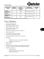
We reserve the right to implement technical modifications.
Version / Characteristics
• Material: high-alloy steel;
• Power type: Exhaust air
• Mounting type: Wall mounting
• Flame protection filter: Type A
• Filter material: Stainless steel
• Protection class: IP54
• Number of fan motors/exhaust air outputs: 1
• Motor output: 145 W
• Fan control: Via external controller
• Opening for motor: 233 x 200 mm
• Connected load: 0.153 kW / 230 V / 50–60 Hz
• Lighting:
– LED
– integrated by means of non-dazzle installation
– with grease protection cover
• Lights: 1 x 8 W
• Filter bracket
• Welded-on grease collection channel with discharge tap
• Can only be put into operation with additional controller
• Available on demand:
– other dimensions
– extractor hood with 1,100 mm depth
– ceiling extractor hoods

Technical Data
10 / 22 271107
EN
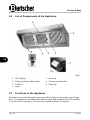
4.2 List of Components of the Appliance
Fig. 1
1. LED lighting
2. Housing
3. Flame protection filter holder
4. Flame protection filter
5. Partition
6. Drain tap
7. Motor
4.3 Functions of the Appliance
Extractor hoods with integrated motors provide for high venting power over a large
area. The appliances are adapted to wall mounting and equipped with LED lighting.
To put them into operation, an external fan speed regulator is required.

Installation and operation
271107 11 / 22
EN
5 Installation and operation
5.1 Installation
CAUTION!
Incorrect installation, positioning, operation, maintenance or misuse of
the appliance may lead to personal injury or property damage.
Positioning and installation, as well as repairs may be performed by
authorised technical service only and in compliance with the applicable
national law.
NOTE!
The manufacturer disclaims all liability and provides no warranty for
damages, which may be attributed to non-observance of regulations or
incorrect installation.
Unpacking / Mounting
• Unpack the appliance, remove all external and internal packaging elements and
shipment safeguards.
CAUTION!
Choking hazard!
Prevent children from accessing packaging materials, for instance: plastic
bags and EPS elements.
• If the appliance is covered with a protective film, remove it. Remove the film
slowly, so no glue residues are left. Remove any glue residues with the use of a
suitable solvent.
• Be careful not to damage the rating plate and warning labels affixed to the
appliance.
• The appliance should be installed in a room, in which ambient temperature falls
in the range of +5°C – +60°C.
• Place the appliance in a manner making the connections easily accessible, so
that they may be quickly disconnected if such a need arises.
• During installation, make sure ventilation openings are not covered nor blocked.
• Install the appliance in rooms with sufficient air circulation.

Installation and operation
12 / 22 271107
EN
• When installing extractor hoods over gas or open-flame appliances, provide for
sufficient air inflow.
• Maintain sufficien t clearance fro m both sides an d the back of th e appliance ag ainst walls or oth er objects to avoid exposur e to heat. Sh ould this not be possible, install pr otective de vices, for exa mple films made of heat-resistant material.
Wall Mounting
The extractor hood must be located over an appliance (e.g. an oven, a grill plate,
etc.).
The external side of the extractor hood must protrude 200–400 mm beyond a
heating field.
The extractor hood must be located at the height of 1,900–2,000 mm over a floor
and the distance to a heating field must be 1,000 mm.
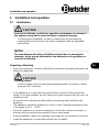
The extractor hood is mounted to the wall with a specially enclosed installation
brackets. During transportation, they are affixed to the housing of the appliance.
Unscrew the installation brackets from the housing.
The location and number of installation brackets differ depending on the size of an
appliance. The below figure presents a schematic view of the number and location
of brackets in various models.
Fig. 2

Installation and operation
271107 13 / 22
EN
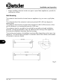
1. Using information provided in the figure, mark points on the wall for boreholes.
2. Bore the holes.
3. Insert the studs into the bored holes.
4. Screw the appropriate number of installation brackets to the wall.
5. Hang the extractor hood on the installation brackets.
Fig. 3
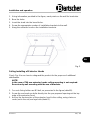
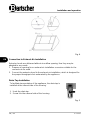
Ceiling Installing of Extractor Hoods
Check Fig. 4 to see how to safeguard the product for the purpose of additional
stabilization.
NOTE!
In the case of 700 mm extractor hoods ceiling mounting is not required.
Execute only wall mounting with the use of brackets.
1. For each fixing holder use M5 bolt, as presented in the figure (detail B).
2. Screw the enclosed eye bolts directly into the pre-prepared openings at the top
edge of the extractor hood.
3. Anchor the front section of the extractor hood in the ceiling, using chains or
cords (not in the set) and eye bolts (detail C).

Installation and operation
14 / 22 271107
EN
Fig. 4
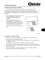
Connection to Exhaust Air Installation
Extractor hoods are delivered without air outflow opening, thus they may be
adapted to any needs.
1. Prepare an opening for an exhaust air installation connector suitable for the
connector to be used.
2. Connect the extractor hood to the exhaust air installation, which is designed for
the proper throughput of air exhausted by the appliance.
Drain Tap Installation
To facilitate transportation of the appliance, the drain tap is
installed at the internal side of the housing.
1. Undo the drain tap.
2. Screw it to the external side of the housing.
Fig. 5

Installation and operation
271107 15 / 22
EN
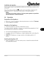
Flame Protection Filters Installation
1. Unpack the delivered flame protection filters and, if needed, partitions.
Flame protection filters are fitted in a specially formed fat collection element. The
internal profile of the extractor hood is formed in a way making it possible for
condensate/fat to accumulate in the fat collection channel and are delivered to the
drain tap.
2. After installing the extractor hood on the
wall, fit the appliance with flame
protection filters and partitions (if
needed):
– use the holders to fit the flame
protection filters in the top guide-rail of
the available opening first, then move
them upwards as far as possible and let
them slide to the bottom guide-rail.
– fit the partition between flame protection
filters.
Fig. 6
Connection — Electrical Power
• Verify if the technical specification of the appliance (see the rating plate)
corresponds to the local electricity grid.
• The power cord should be laid in a way preventing anyone from threading on it
or tripping against it.
• The appliance is supplied with a connection cable without a plug.
• It is of utmost necessity to install proper disconnector of all poles upstream of
the appliance, so that — when needed — the appliance is quickly disconnected
from power supply.
• Moreover, establish a correct grounding connection, according to safety
regulations pertaining to electrical installation.

Installation and operation
16 / 22 271107
EN
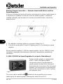
Electrical Power Connection — Extractor Hoods with Motors and Fan
Speed Regulators
In the case of extractor hoods with motors and exhaust air volume control means, it
is necessary to establish a connection via a fan speed regulator. It should be
installed externally, wall-mounted, in an easily accessible location, next to the
extractor hood.
Fig. 7
1. Pay attention to wiring outlets for connection cables (Fig. 7).
2. Connect the motor wire (D) and LED lighting wire (E) to a suitable fan speed
regulator.
We recommend installing 1–2,200 fan speed regulator / art. No. 220120. Follow
indications contained in manufacturer's instruction manual when establishing
connection.
1–2,200 / 220120 Fan Speed Regulator (is not part of the delivery!)
The fan speed regulator is equipped with
ON/OFF switch and lighting switch.
Fan speed control is executed with fan
speed regulator located at the front panel.
By removing the front panel of the fan speed
regulator, you may access the terminal strip
and execute connections for motor, lighting
and magnetic valve.
Fig. 8
The rocker switch marked with provides for the possibility of concurrent
switching the fan speed regulator and magnetic valve ON and OFF.

Installation and operation
271107 17 / 22
EN
The fan speed control is executed alike, with the use of the rotary controller on the
front panel.
The rocker switch marked with provides for the possibility of switching LED
lighting ON and OFF, irrespective of the position of fan speed regulator.
NOTE!
Information about other settings of the fan speed regulator are provide in
the manufacturer's instruction manual.
5.2 Operation
• Prior to first opera tion, clean the a ppliance and its equipment ac cording to instr uctions in sect ion 6 'Cle aning'. Make sur e no water e nters electric installa tion and connec tion box. Then thoroughly dr y the appliance a nd the entire eq uipment.
• Insert the botto m cover into the appliance. The c over acts as a sp acer between the heating ele ment and left -over food tray.
• Carefully insert t he connection b ox with the heati ng element at th e back edge of t he applianc e. A pin in botto m part of the c onnection bo x must enter a hole in the main appliance. This way the con nection box is pro perly mounted.
Preparation of the Appliance
1. Before use, clean the appliance, observing instructions in section 6 'Cleaning'.
2. Dry the appliance thoroughly.
Operation of the Appliance
1. Switch the appliance on with the installed disconnector.
The extractor hood is switched on. Vapours are vented during preparation of food
and exhausted by the exhaust air installation.
2. Use the fan speed regulator to set the required motor speed.
3. If needed, switch the LED lighting on, using the lighting switch, and setting it to
'I' position.
4. When the LED lighting is no longer needed, set the lighting switch to 'O'
position.
Switching the Appliance Off
1. When the appliance is not to be used any more, it should be switched off with
the installed disconnector.

Cleaning and Maintenance
18 / 22 271107
EN
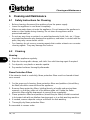
6 Cleaning and Maintenance
6.1 Safety Instructions for Cleaning
• Before cleaning, disconnect the appliance from the power supply.
• Leave the appliance to cool down completely.
• Make sure water does not enter the appliance. Do not immerse the appliance in
water or other liquids during cleaning. Do not clean the appliance with a
pressurized water jet.
• Do not use any sharp or pointed, nor metal implements (knife, fork, etc.). Sharp
or pointed implements may damage the appliance, and when in contact with live
parts, they may cause electric shock.
• For cleaning, do not use any scouring agents that contain solvents nor corrosive
cleaning agents. They may damage the surface.
6.2 Cleaning
Housing
1. Wash the appliance regularly.
2. Wipe the housing with a damp, soft cloth. Use mild cleaning agent if required.
3. For deposits, use plastic or wooden spatula.
4. Dry washed surfaces thoroughly afterwards.
Flame Protection Filters
If the extractor hood is used daily, flame protection filters must be cleaned at least
once a week.
1. For the purpose of cleaning, flame protection filters and partitions (should they
be fitted) should be removed from the appliance.
2. Remove flame protection filters, holding them by a handle and moving them
upwards, so that they slide out of the bottom guide-rail. Rotate the flame
protection filters slightly downwards to remove them completely.
3. Flame protection filters and partitions (should they be fitted) should be washed
in hot water bath with an alkaline cleaning agent or in a dish-washing machine.
4. If needed, remove deposits using a soft brush for dish-washing.
5. Thoroughly dry flame protection filters.
Re-assemble in reverse order.
Page is loading ...
Page is loading ...
-
 1
1
-
 2
2
-
 3
3
-
 4
4
-
 5
5
-
 6
6
-
 7
7
-
 8
8
-
 9
9
-
 10
10
-
 11
11
-
 12
12
-
 13
13
-
 14
14
-
 15
15
-
 16
16
-
 17
17
-
 18
18
-
 19
19
-
 20
20
-
 21
21
-
 22
22


Bartscher 271177 Operating instructions
- Type
- Operating instructions
Ask a question and I''ll find the answer in the document
Finding information in a document is now easier with AI
Related papers
-
Bartscher 825207 Operating instructions
-
-
-
Bartscher A370131 Operating instructions
-
Bartscher A150674 Operating instructions
-
-
Bartscher A135034 Operating instructions
-
Bartscher 700834 Operating instructions
-
Bartscher A150673 Operating instructions
-
Other documents
-
Woodstock SHOP FOX W1800 User manual
-
 Lec Commercial U50052W (444441942) (GD258) User manual
-
 Musical Fidelity M8S-700m Product information
-
LEC R5009 Owner's manual
-
-
Aeg-Electrolux E43012-5-W User manual
-
AEG 155D-W User manual
-
-
-

