
Manual for use and maintenance
CO2 Sensor
Climate Controller
Ag/MIS/UmGB-2064-02/13 Rev 1.0
P/N: 117329
CO2
Sensor

© Munters AB, 2018 2
CO2 Sensor
Manual for use and maintenance
Rev 1.9 01/2019
Ag/MIS/UmGB-2064-02/13 Rev 1.3 (MIS)
This manual for use and maintenance is an integral part of the apparatus together with the attached
technical documentation.
This document is destined for the user of the apparatus: it may not be reproduced in whole or in part,
committed to computer memory as a file or delivered to third parties without the prior authorization of
the assembler of the system.
Munters reserves the right to effect modifications to the apparatus in accordance with technical and
legal developments.

© Munters AB, 2018 3
Table of Contents
1
INTRODUCTION ------------------------------------------------------------------------------------------------------------------------------------------ 4
1.1
Disclaimer
--------------------------------------------------------------------------------------------------------------------------------------------------------------------------------
4
1.2
Introduction
-----------------------------------------------------------------------------------------------------------------------------------------------------------------------------
4
1.3
Notes
-----------------------------------------------------------------------------------------------------------------------------------------------------------------------------------------
4
2
INTRODUCTION ------------------------------------------------------------------------------------------------------------------------------------------ 5
2.1
Features
------------------------------------------------------------------------------------------------------------------------------------------------------------------------------------
5
2.2
Operating Mode
-----------------------------------------------------------------------------------------------------------------------------------------------------------------
6
3
INSTALLATION ---------------------------------------------------------------------------------------------------------------------------------------------- 7
3.1
Installing the Sensor
----------------------------------------------------------------------------------------------------------------------------------------------------------
7
3.2
Controller Connection
------------------------------------------------------------------------------------------------------------------------------------------------------
9
3.2.1
Platinum Wiring
......................................................................................................................
9
3.2.2
Platinum Pro Wiring
.............................................................................................................
10
3.2.3
AC-2000 Plus Wiring
..........................................................................................................
12
3.3
Calibrating the Device
--------------------------------------------------------------------------------------------------------------------------------------------------
13
3.4
Disconnecting the Sensor
--------------------------------------------------------------------------------------------------------------------------------------------
14
4
MAINTENANCE AND CARE ----------------------------------------------------------------------------------------------------------------- 15
5
SPECIFICATIONS -------------------------------------------------------------------------------------------------------------------------------------- 15
6
TROUBLESHOOTING ------------------------------------------------------------------------------------------------------------------------------ 16
7
WARRANTY ------------------------------------------------------------------------------------------------------------------------------------------------- 17

© Munters AB, 2018 4
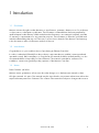
1 Introduction
1.1 Disclaimer
Munters reserves the right to make alterations to specifications, quantities, dimensions etc. for production
or other reasons, subsequent to publication. The information contained herein has been prepared by
qualified experts within Munters. While we believe the information is accurate and complete, we make
no warranty or representation for any particular purposes. The information is offered in good faith and
with the understanding that any use of the units or accessories in breach of the directions and warnings
in this document is at the sole discretion and risk of the user.
1.2 Introduction
Congratulations on your excellent choice of purchasing an Element Controller!
In order to realize the full benefit from this product it is important that it is installed, commissioned and
operated correctly. Before installation or using the fan, this manual should be studied carefully. It is also
recommended that it is kept safely for future reference. The manual is intended as a reference for
installation, commissioning and day-to-day operation of the Munters Controllers.
1.3 Notes
Date of release: Jan 2018
Munters cannot guarantee to inform users about the changes or to distribute new manuals to them.
All rights reserved. No part of this manual may be reproduced in any manner whatsoever without the
expressed written permission of Munters. The contents of this manual are subject to change without notice.

© Munters AB, 2018 5
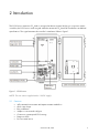
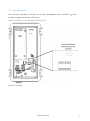
2 Introduction
The CO2 Sensor measures CO
2
levels in an agricultural environment. Working in conjunction with a
controller, the CO2 Sensor sends a signal when the measured CO
2
levels fall outside the user-defined
specifications. This signal activates the controller’s ventilation. Refer to Figure 1.
Figure 1: CO2 Sensor
NOTE The unit comes supplied with a 12 VDC supply.
2.1 Features
• Self-contained environment and impact-resistant sealed box
• Quick open clasps
• Easy installation
• Simple to connect and configure
• Continuous uninterrupted CO2 sensing
• Diagnostic LEDs
• Door-mounted sensor


© Munters AB, 2018 7
3 Installation
This section details:
• Installing the Sensor
• Controller Connection
• Calibrating the Device
• Disconnecting the Sensor
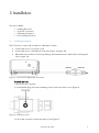
3.1 Installing the Sensor
The CO2 Sensor comes with an extension cable that is used to:
• Connect the sensor to a power source
• Connect the sensor to the Platinum Controller (Figure 10, page 10)
• Detach the unit from the house during cleaning and maintenance procedures (Disconnecting the
Sensor, page 14)
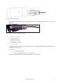
Figure 3: CO2 Sensor Attached to Connector
To install the unit:
1. Mount the sensor in place.
2. On the female plug, remove the retaining screw from the protective cover (Figure 4).
Figure 4: Protective Cover
3. Pull out the connector from the protective cover (Figure 5).

© Munters AB, 2018 8
Figure 5: Remove the Connector
4. Place the cable through the protective cover (Figure 6).
Figure 6: Threading the Cable
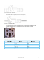
5. On the top of the connector are numbers (Figure 7. Each wire must be attached to the
corresponding port (Table 1). Connect the four wires to the connector Figure 8.
Figure 7: Connector Numbers
Table 1: Connecter Port Functions
Port Number
Function
Wire Color
1 +12 V Red
2 12 V Com (-) Black
3 SIG Out White
4 SIG Com Green

© Munters AB, 2018 9
Figure 8: Wired Connector
6. Place the wired connector back into the protective cover and place the retaining screw in place
(Figure 9).
Figure 9: Wired Unit in Protective Cover
3.2 Controller Connection
• Platinum Wiring
• Platinum Pro Wiring
• AC-2000 Plus Wiring
3.2.1 P
LATINUM
W
IRING
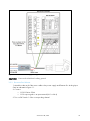
1. Attach the other end of the sensor cable to the power supply and Platinum Analog Input Card
as indicated in Figure 10.
2. Connect:
o
CO2 COM to COM
o
CO2 output signal to the T5 or T6 terminal
3. Place a jumper on the T5 or T6 pins (sets the 4 – 20 mA mode).

© Munters AB, 2018 10
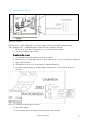
Figure 10: Platinum Power Supply Wiring
CAUTION
Connect the shield to the safety ground.
3.2.2 P
LATINUM
P
RO
W
IRING
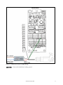
1. Attach the other end of the sensor cable to the power supply and Platinum Pro Analog Input
Card as indicated in Figure 11.
2. Connect:
o
CO2 COM to COM
o
CO2 output signal to an input terminal (IN 1 to IN 4)
3. Turn on DIP Switch 1 of the corresponding channel.

© Munters AB, 2018 11
Figure 11: Platinum Pro Power Supply Wiring
CAUTION
Connect the shield to the safety ground.

© Munters AB, 2018 12
3.2.3 AC-2000
P
LUS
W
IRING
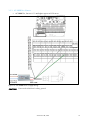
• AC-2000 Plus, Version 8.11 and higher support a CO2 sensor.
Figure 12: AC-2000 Power Supply Wiring
CAUTION
Connect the shield to the safety ground.

© Munters AB, 2018 13
3.3 Calibrating the Device
Figure 13: Jumpers
The C02 sensor comes calibrated. In normal conditions fresh air should have approximately
350 - 450 ppm CO2. Calibrate the device if the following conditions are met:
• The CO2 sensor is exposed to fresh air or a room with open windows
• The sensor reading is above 550
To calibrate the sensor:
1. If connected, disconnect the device from the controller.
2. Place the sensor on a steady base (in an area with fresh air or in a room with open windows).
3. Apply 12V DC power.
4. Operate the CO2 sensor for five minutes to stabilize the device.
5. Using the supplied jumper, short the Background jumpers for 10 seconds as shown in
Figure 14.
Figure 14: Shorting the Background Jumpers
6. Remove the jumper.
7. Disconnect the power and (re)connect the sensor to the controller.

© Munters AB, 2018 14
CAUTION
Do not short the Zero jumpers; they are for factory-calibration only. If shorted, remove
the jumper and calibrate again.
NOTE If the device reading is still above 550 when exposed to fresh air, repeat the process.
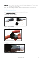
3.4 Disconnecting the Sensor
Before cleaning the poultry/animal house, disconnect the CO2 sensor.
To disconnect the sensor:
1. Dismount the sensor from the wall.
2. Separate the male and female plugs.
Figure 15: Plugs Separated
3. Place the plug cap on the female cap.
Figure 16: Cap in Place
4. Snap the cap into place.
Figure 17: Cap Snapped into Place

© Munters AB, 2018 15
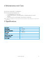
4 Maintenance and Care
The CO2 Sensor requires little or no maintenance.
The following are general maintenance rules:
• Avoid damaging the CO2 Sensor box
• Avoid contact with water or other fluids (when you clean the poultry house, remove
the box)
• Ensure sensor grill on front box panel is clean and clear of obstructions
NOTE Water may damage the sensor; therefore minimize exposure while washing, or using water for
any purpose.
5 Specifications
Input signal
12 VDC
Output signal
4 – 20 mAmp
Operating temperature
10 º - 70º C
CO2 range
0 – 5000 ppm
Accuracy
1%
Maximum cable length
300 meters
Minimum wire size
22 AWG
Power supply
12 VDC

© Munters AB, 2018 16
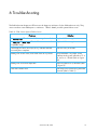
6 Troubleshooting
The field technician diagnostic LEDs are visual diagnostic indicators for the field technician only. They
are not end-user serviceable parts or indicators. Table 2 details possible system failure issues.
Table 2: CO2 Sensor System Failure Issues
Problem
Solution
The
Sensor Fail
LED is lit when CO2 sensing element fails. Replace CO2 sensing element
The
Min.Fail
or
Max. Fail
LED is lit: The sensor is out of
acceptable range.
Replace CO2 sensing element
If the diagnostic LEDs are lit (D2, R12), indicates that the
circuit may be incomplete.
Check circuitry for breaks
Readings are off the scale, even when fresh air is present. Verify that there is a jumper on the
Platinum Analog card, placed on T5 or
T6, set for 4 – 20 mA (refer to Figure
10).
Readings are lower than expected. Remove jumper from J2 terminal (refer
to Figure 2).
Power LED remains unlit Check if power/COM wiring has been
reversed (refer to Table 1).

© Munters AB, 2018 17
7 Warranty
Warranty and technical assistance
Munters products are designed and built to provide reliable and satisfactory performance but cannot be
guaranteed free of faults; although they are reliable products they can develop unforeseeable defects
and the user must take this into account and arrange adequate emergency or alarm systems if failure to
operate could cause damage to the articles for which the Munters plant was required: if this is not done,
the user is fully responsible for the damage which they could suffer.
Munters extends this limited warranty to the first purchaser and guarantees its products to be free from
defects originating in manufacture or materials for one year from the date of delivery, provided that
suitable transport, storage, installation and maintenance terms are complied with. The warranty does not
apply if the products have been repaired without express authorization from Munters, or repaired in
such a way that, in Munters’ judgment, their performance and reliability have been impaired, or
incorrectly installed, or subjected to improper use. The user accepts total responsibility for incorrect use
of the products.
The warranty on products from outside suppliers fitted to CO2 sensor Premium, (for example analog
inputs, cables, etc.) is limited to the conditions stated by the supplier: all claims must be made in writing
within eight days of the discovery of the defect and within 12 months of the delivery of the defective
product. Munters has thirty days from the date of receipt in which to take action, and has the right to
examine the product at the customer’s premises or at its own plant (carriage cost to be borne by the
customer).
Munters at its sole discretion has the option of replacing or repairing, free of charge, products which it
considers defective, and will arrange for their dispatch back to the customer carriage paid. In the case
of faulty parts of small commercial value which are widely available (such as bolts, etc.) for urgent
dispatch, where the cost of carriage would exceed the value of the parts, Munters may authorize the
customer exclusively to purchase the replacement parts locally; Munters will reimburse the value of the
product at its cost price.
Munters will not be liable for costs incurred in demounting the defective part, or the time required to travel
to site and the associated travel costs. No agent, employee or dealer is authorized to give any further
guarantees or to accept any other liability on Munters’ behalf in connection with other Munters products,
except in writing with the signature of one of the Company’s Managers.
WARNING! In the interests of improving the quality of its products and services, Munters reserves
the right at any time and without prior notice to alter the specifications in this manual.
The liability of the manufacturer Munters ceases in the event of:
• dismantling the safety devices;
• use of unauthorized materials;

© Munters AB, 2018 18
•
inadequate maintenance;
•
use of non-original spare parts and accessories.
Barring specific contractual terms, the following are directly at the user’s expense:
• preparing installation sites;
• providing an electricity supply (including the protective equipotential bonding (PE) conductor,
in accordance with CEI EN 60204-1, paragraph 8.2), for correctly connecting the equipment
to the mains electricity supply;
• providing ancillary services appropriate to the requirements of the plant on the basis of the
information supplied with regard to installation;
• tools and consumables required for fitting and installation;
• lubricants necessary for commissioning and maintenance.
It is mandatory to purchase and use only original spare parts or those recommended by the manufacturer.
Dismantling and assembly must be performed by qualified technicians and according to the
manufacturer’s instructions.
The use of non-original spare parts or incorrect assembly exonerates the manufacturer from all liability.
Requests for technical assistance and spare parts can be made directly to the nearest Munters office. A
full list of contact details can be found on the back page of this manual.
Munters USA
2691 Ena Drive
Lansing, MI 48917-8521
United States
Tel: +1 517 676 7070
Toll Free: +1 800 227 2376
Fax: +1 517 676 7078
Email: aghort.in[email protected]

© Munters AB, 2018
www.munters.com
Australia Munters Pty Limited, Phone +61 2 8843 1594, Brazil Munters Brasil Industria e Comercio Ltda, Phone +55 41 3317 5050, Canada Munters Corporation
Lansing, Phone +1 517 676 7070, China Munters Air Treatment Equipment (Beijing) Co. Ltd, Phone +86 10 80 418 000, Denmark Munters A/S, Phone
+45 9862 3311, India Munters India, Phone +91 20 3052 2520, Indonesia Munters, Phone +62 818 739 235, Israel Munters Israel Petach Tikva
+972 3 920 6200 Italy Munters Italy S.p.A., Chiusavecchia, Phone +39 0183 52 11, Japan Munters K.K., Phone +81 3 5970 0021, Korea Munters Korea Co. Ltd.,
Phone +82 2 761 8701, Mexico Munters Mexico, Phone +52 818 262 54 00, Singapore Munters Pte Ltd., Phone +65 744 6828, South Africa and Sub-Sahara
Countries Munters (Pty) Ltd., Phone +27 11 997 2000, Spain Munters Spain S.A., Phone +34 91 640 09 02, Sweden Munters AB, Phone +46 8 626 63 00,
Thailand Munters Co. Ltd., Phone +66 2 642 2670, Turkey Munters Form Endüstri Sistemleri A.Ş, Phone +90 262 751 37 50, USA Munters Corporation Lansing,
Phone +1 517 676 7070, Vietnam Munters Vietnam, Phone +84 8 3825 6838, Export & Other countries Munters Italy
S.p.A., Chiusavecchia Phone
+39 0183 52 11
Ag/MIS/UmGB-2064-02/13 Rev 1.0
-
 1
1
-
 2
2
-
 3
3
-
 4
4
-
 5
5
-
 6
6
-
 7
7
-
 8
8
-
 9
9
-
 10
10
-
 11
11
-
 12
12
-
 13
13
-
 14
14
-
 15
15
-
 16
16
-
 17
17
-
 18
18
-
 19
19


Ask a question and I''ll find the answer in the document
Finding information in a document is now easier with AI
Related papers
-
Munters Green CO2 Sensor Climate Controller User manual
-
-
-
-
-
-
-
-
-
Munters 116857 User manual