
Installation
Instructions
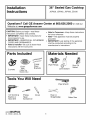
36" Sealed Gas Cooktop
JGP628, JGP962, JGP963, ZGU36
Questions? Call GE Answer Center at 800.626.2000 or visit our
Website at: www.geappliances.com
CAUTION: Before you begin--read these
instructions completely and carefully.
• IMPORTANT--Save these instructions for
local inspector's use.
• IMPORTANT--OBSERVE ALL GOVERNING
CODES AND ORDINANCES.
• Note to Installer--Be sure to leave these
instructions with the Consumer.
• Note to Consumer--Keep these instructions
for future reference.
• Note--This appliance must be properly
grounded.
• IMPORTANT: Leak testing of the appliance
shall be conducted according to the
manufacturer's instructions.
Parts Included
2 Hold
Foam Down
Tape Brackets
2 screws (Glass Top
Models Only)
Materials Needed
Pipe Fittings
J
Joint Sealant
Shut Off
Valves
Tools You Will Need
1/8" Drill Bit & Phillips Pencil
Electric or Head
Hand Drill Screwdriver
Pipe Wrench
Ruler or
Straightedge
Saber Saw
229c4053P522
31-10539 (08-02 JR)

Installation Instructions
IMPORTANT SAFETY INSTRUCTIONS
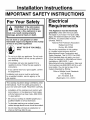
For Your Safety
WARNING!! If the informationin this manual is not followed
exactly, a fire, explosion or gas
leak may result causing property
damage, personal injury or death.
Do not store or use gasoline or other
flammable vapors and liquids in the vicinity
of this or any other appliance!
WHAT TO DO IF YOU SMELL
GAS:
• Do not try to light any appliance. Do not touch
any electrical switch; do not use any phone in
your building.
• Immediately call your gas supplier from a
neighbor's phone. Follow the gas supplier's
instructions.
• If you cannot reach your gas supplier, call the
fire department.
Installation and service must be performed
by a qualified installer, service agency or the
gas supplier.
Electrical
Requirements
This Appliance must be electrically
grounded. Check with the local codes
that apply in your area. If no local codes
apply, the National Electrical Code, ANSI/
NFPA No. 70-Latest Edition must be
followed. Write to:
National Fire Protection Association
Batterymarch Park
Quincy, MA 02269
Be sure the installation of this cooktop
in a mobile home conforms with the
Manufactured Home Construction and
Safety Standard, Title 24 CFR, Part 3280.
If this standard does not apply, you must
follow the standard for Manufactured Home
Installations, ANSI A225.1 and
Manufactured Home Installations, Sites and
Communities and ANSl/NFPA 501A or with
local codes. You can get a copy of the
Federal Standard by Writing:
Office of Mobile Home Standards
HUD Building
451 7th Street, S.W.
Washington, D.C. 24010
This cooktop has been design certified by CSA
International. You'll find safety precautions in
your Use and Care Guide. Read them carefully.
Installation of this cooktop must conform with
local codes or, in the absence of local codes,
with the National Fuel Gas Code, ANSI Z223.
1-Latest edition.
• Be sure your cooktop is installed properly by a
qualified installer or service technician.
• To eliminate reaching over surface burners,
cabinet storage above burner should be avoided.
• Do not install the unit near an outside door or
where a draft may affect its use.
2

Installation Instructions
Pre-lnstallation Checklist
[_ When preparing cooktop opening, [_
make sure the inside of the cabinet
and the cooktop do not interfere with
each other. (See section on preparing
the opening.)
Remove packaging materials and
literature package from the cooktop
before beginning installation.
Styrofoam _ Literature Package
Remove Installation Instructions
from literature pack and read them
carefully before you begin.
Be sure to place all literature, Use
and Care, Installations, etc. in a safe
place for future reference.
Make sure you have all the tools and
materials you need before starting the
installation of the cooktop.
Your home must provide the adequate
electrical service needed to safely and
properly use your cooktop. (Refer to
section on electrical requirements.)
When installing your cooktop in your
home, make sure all local codes and
ordinances are followed exactly as
stated.
Make sure the wall coverings,
countertop and cabinets around the
cooktop can withstand heat (up to
200°F) generated by the cooktop.
3

Installation Instructions
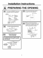
The following MINIMUM clearance
dimensions must be maintained.
6" MIN.
clearance from
/cutout to side
wa]l on the right
of the unit
,18" MIN.
height from
countertop to
nearest cabinet on
either side of unit
13" MAX, Depth
of unprotected _
overhead cabinets
3O" MIN,
clearance from
J
countertop to
unprotected
overhead surface .
clearance from _cutout to side
wall on the left
of the unit I _ _11•
Overall cooktop dimensions
36" _'_" 21"
_ 3"
Cutout dimensions
of the countertop
i o insure accuracy, it is best to make Ill
a template when cutting the opening
F;
in the counter.
19 1/8" width of cut
2
Between cutout
and the wall behind
the cooktop
2 1/2"Min.
from front edge
of cutout
and front edge
of countertop
OP NING
The recommended Gas Supply
Location from the backwall.
Recommended
gas supply
location.
l"Min. From Backwall
c)
/_ From Cutout
J
Center Line
Make sure the wall coverings,
countertop and cabinets around the
cooktop can withstand heat (up to
200°F) generated by cooktop.
Wall covering,
cabinets and
countertop
must withstand
heat u_
4

Installation Instructions
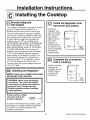
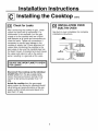
Installing the Cooktop Unit
Locate the electrical outlet
and the Gas Shut Off valve
beneath the cabinet,
NEVER REUSE _J
II
OLD CONNECTORS ll\
Shut Off I Electrical
WHEN INSTALLING Va,vo--' , outlot
THIS UNIT. L] I t2..Bo,ow
Countertop
Install a manual shutoff valve in the gas line in
an easily accessible location outside the cooktop.
Be sure you know how and where to shut off the
gas supply to the cooktop. Install the electrical
outlet 12" below the countertop.
I-B--_Protect the Surface
of the Cooktop
Place a towel or tablecloth onto the
countertop. Lay the cooktop upside down
onto the protected surface.
Bottomof_ok_op
Cloth un_r Co_k_op
Attach the Adhesive Strip
(Glass Top Models Only)
Attach the adhesive strip around the maintop
glass as close to the edge as possible.
Outer edge
of glass bottom
Cooktop I.-_...._
Burner Adhesive Strips
Box to outer edge
of glass
Countertop
I-B--_Attach Brackets to Cooktop
Remove the screw from the bottom of the
cooktop. Screw the hold down bracket to the
side of the cooktop unit. Repeat for opposite
side of cooktop.
Pre-drilled
Bottom of hole
Cooktop /_O_
Foam Strips
Cooktop
I-B--_Insert Cooktop Into Cutout
Insert the cooktop centered into the cutout
opening. Make sure the front edge of the
countertop is parallel to the cooktop. Make
final check that all required clearances are
met.
Once the unit is in place, screw the hold
down bracket into the cabinet sides to
secure the unit into place.
I-_ Locate The Mounting Parts
Remove the hold down brackets from the
literature package.
5

Installation Instructions
Installing the Cooktop
_--_ Provide Adequate
Gas Supply
This cooktop is designed to operate on natural
gas at 4" of water column pressure. It is
shipped from the factory set for natural gas.
The convertible pressure regulator supplied
with the unit must be connected in series with
the manifold of the cooktop and must remain
in series with the supply line regardless of
whether natural or L.P. gas is being used.
FOR PROPER OPERATION, THE MAXIMUM
INLET PRESSURE TO THE REGULATOR
MUST BE NO MORE THAN 14" OF WATER
COLUMN PRESSURE. For checking the
regulator, the inlet pressure must be at least
1" (or 3.4 KPA) greater than the regulator
output setting. If the regulator is set for 4" of
water column pressure, the inlet pressure
must be at least 5". If the regulator is set for
10", the inlet pressure must be at least 11".
The gas supply line to the cooktop should be
1/2" or 3/4" pipe.
Installing the Regulator
NEVER REUSE OLD CONNECTORS WHEN
INSTALLING THIS COOKTOP.
WARNING: Never reuse old flexible
connectors. The use of old flexible
connectors can cause gas leaks and
personal injury. Always use new
flexible connectors when installing
a gas appliance.
Screw a section of pipe I1
onto each end of the Pressure
pressure regulator. Regulator
To reduce the likelihood of gas leaks, apply
teflon tape or a thread compound approved
for use with LP or Natural gases to all
threaded connections.
Install the Regulator onto
the burner box bottom.
Screw the
regulator and
pipe connection
into the burner
box bottom.
Make sure the
top of the
regulator is
facing towards
the cabinet front,
easily accessible
through the
cabinet doors.
I
I
Pressure _t
Regulator
tJ
El
Shut Off q_
Valve
!\
I Electrical
I Outlet
II 12" Below
Countertop
_-_ Complete the connection
with a coupling.
Install a coupling
between the
regulator and the
shutoff valve to
complete the
connection.
Pressure
Regulator _t
Coupling _I
Shut Off
Valve
_=_
dJ
I i
I Electrical
I Outlet
I 12" Below
Countertop
6 continue on the following page

Installation Instructions
Installing the Cooktop cont.
I_ Check for Leaks
After connecting the cooktop to gas, check
system for leaks with a manometer. If a
manometer is not available, turn the gas
supply on to the cooktop and use a liquid
leak detector at all joints and connections to
check for leaks. Tighten all connections if
necessary to prevent gas leakage in the
cooktop or supply line. Check alignment of
valves after connecting the cooktop to the
gas supply to be sure the manifold pipe has
not been moved. A misalignment could cause
the valve knob stem to rub on the control
panel, resulting in a gas leak at the valve.
DO NOT USE OPEN FLAME TO CHECK
FOR LEAKS!
Disconnect this cooktop and its individual
shutoff valve from the gas supply piping
system during any pressure testing of that
system at test pressures greater than 1/2"
psig.
Isolate the cooktop from the gas supply
piping system by closing its individual shutoff
valve during any pressure testing of the gas
supply system at test pressures equal to or
less than 1/2" psig.
_--6] INSTALLATION OVER
BUILT-IN OVEN
See built-in oven installation for complete
installation instructions.
I
T
5"TO CENTER
OF 2" DIA. HOLE
FROM COUNTERTOP
STREET EL
CABINET BIDES _ 7
2"_A. HOLE(207_"
FROM FRONTOF
COUNTERTOPTO
HOLECENTER)
7

Installation Instructions
Installation---ElectricalConnections
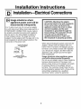
Because of potential safety hazards,
under certain conditions we strongly
recommend against the use of an
extension cord. However, if you still elect
to use an extension cord, it is absolutely
necessary that it be a UL listed 3-wire
grounding type appliance extension cord
and that the current carrying rating of the
cord in amperes be equivalent to or
greater than the branch circuit rating.
Such extension cords are obtainable
through your local appliance dealer.
i[ MPORTANT: (Please read carefully) FOR 1!
PERSONAL SAFETY, THIS APPLIANCE
MUST BE PROPERLY GROUNDED.
_--_ Where a standard two-prong wall
receptacle is encountered, it is the
personal responsibility and obligation
of the customer to have it replaced
with a properly grounded three-prong
wall receptacle.
Do not under any circumstances cut or
remove grounding prong from the
cooktop cord. Failure to provide proper
polarization may create a hazardous
condition.
_--_An adequate electrical supply and outlet
must be used to operate the electrical
parts of your cooktop.
a. The power cord of this appliance is
equipped with a three-prong (grounding)
plug which must be used with a properly
grounded three-hole outlet with a standard
120 Volt, 60 cycle AC household current.
b. If you do not have a three-hole grounded
outlet, have a qualified electrician change
your old one.
c. A grounding adaptor will be needed to
convert the old one until the outlet can be
replaced. This method is only temporary,
and a qualified electrician should test it to
be sure it meets requirements.
Insure proper
ground and
firm connection
before use
8 continued on following page

Installation Instructions
Installation---ElectricalConnections
Usage situations where
appliance power cord will be
disconnected infrequently.
For 15 amp circuit only. Do not use an adaptor
on a 20 amp circuit. Where local codes permit, a
TEMPORARY CONNECTION may be made to
a properly grounded two-prong wall receptacle
by the use of a UL listed adaptor available at
most hardware stores. The larger slot in the
adaptor must be aligned with the large slot in the
wall receptacle to provide proper polarity in the
connection of the power cord.
Insure proper ground
IE and firm connection
II (_'l-.. / before use
Align large
prongs/slots
Temporary Method
(Adaptor plugs not permitted
in Canada)
CAUTION: Attaching the adaptor
ground terminal to the wall receptacle
cover screw does not ground the
appliance unless the screw is metal,
and not insulated, and the wall
receptacle is grounded through the
house wiring. The customer should
have the circuit checked by a
qualified electrician to make sure
the receptacle is properly grounded.
When disconnecting the power cord from the
adaptor, always hold the adaptor with one
hand. If this is not done, the adaptor ground
terminal is very likely to break with repeated
use. Should this happen, DO NOT USE the
appliance until a proper ground has again
been established.
Usage situations where appliance power
cord will be disconnected frequently.
Do not use an adaptor plug in these situations
because disconnection of the power cord
places undue strain on the adaptor and leads
to eventual failure of the adaptor ground
terminal. The customer should have the two-
prong receptacle replaced with a three-prong
(grounding) receptacle by a qualified
electrician before using the appliance.

Installation Instructions
CooktopBurners
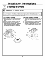
Assembling the Cooktop Burners
I The electrode of the spark igniter is exposed. Be careful not to push any cooktop controls while
the top of the burner is removed. Do not remove the top or touch the electrode of any burner while
another burner is turned on. Electrical shock might result.
For Porcelain Cooktops
a. Place the burner head on the burner base, so
that the pins match up with the slots on the
base.
b. Position the burner cap on the burner head.
c. Place the burner grate over the burner
assembly on the porcelain units. The bottoms
of the burner grates have feet that fit into
corresponding indentations in the cooktop.
For Glass Ceramic Cooktops
a. Place the burner head on the burner base, so
that the pins match up with the slots on the
base.
b. Position the burner cap on the burner head.
c. Place the burner grate over the burner
assembly on the porcelain units. The grates
fit over the raised area on the burner head.
BURNER
GRATE _'_i_
BURNER _
CAP_
BURNER
10

Installation Instructions
CooktopBurners
Checking the Igniters
Operation of the electric igniters should be
checked after the cooktop and supply line
have been carefully checked for leaks and
the cooktop has been connected to the
electrical power.
a. Push and turn a burner valve to the LITE
position.
• The burner valve should light when gas
is available to the burner
• Once the burner lights, it should be
turned out of the LITE position.
b. Try each valve separately until all burners
have been checked.
Burner Ignition
Cooktop Spark Ignition--When you turn the
cooktop knob to LITE, the spark igniter
makes a series of electric sparks (ticking
sounds) which light the burner. During a
power failure, the burners will not light
automatically. In an emergency, a cooktop
burner may be lit with a match by following
the steps below.
I WARNING: Lighting gas burners with a
match is dangerous. You should match
light the cooktop burners only in an
emergency.
a. Light a match and hold the flame near the
burner you want to light. Wooden matches
work best.
b. Push in and turn the control knob slowly. Be
sure you are turning the correct knob for the
burner you are lighting.
NOTE: If the burner does not light within five
seconds, turn the knob off and wait one minute
before trying again.
The Burner Flames
Turn each burner on. Flames should be blue
in color with no trace of yellow. The burner
flames should not flutter or blow away from
the burner. The inner cone of the flame
should be between 1/2" and 3/4" long.
1/2" COOKTOP
to _ BURNER
3/4"
Burners should be checked frequently
WARNING: If you attempt to measure
the inner cone of the flame, please use
caution. Burns could result.
11

Installation Instructions
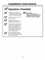
Operation Checklist
[_ Double check to make sure [_
everything in this guide has been
completed. Rechecking steps will
ensure safe use of the cooktop.
Make sure all controls are left in
the OFF position.
Make sure the flow of
combustion and ventilation air to
the cooktop is unobstructed.
The serial plate for your cooktop
is located on the bottom of the
burner box. In addition to the
model and serial numbers, it tells
you the ratings of the burners
and the type of fuel and pressure
the cooktop was adjusted for
when it left the factory.
When ordering parts, always
include the serial number, model
number and a code letter to ensure
proper replacement parts.
Recheck Steps:
Double check to make sure
everything in this guide has been
completed, Rechecking steps will
ensure safe use of the cooktop.
12

LP Conversion
Making the LP Conversion
I-_ Safety Information you
should know
The pressure regulator and burner orifices
are set for natural gas. To use Propane
Gas, the regulator and burner orifices
must be converted. The LP orifice spuds
for the cooktop burners can be located in
the literature package.
CAUTION: The cooktop, as shipped
from the factory, is set for use with
natural gas. If you wish to use your
cooktop with Liquefied Petroleum
(Propane) gas, you must first replace
the orifices and convert the pressure
regulator.
WARNING: This conversion must be
performed by a qualified installer or gas
supplier in accordance with the
manufacturer's instructions and all codes
and requirements of the authority having
jurisdiction. Failure to follow instructions
could result in serious injury or property
damage. The qualified agency performing
this work assumes responsibility for the
conversion.
CAUTION: The following adjustments
must be made before turning on the
burner. Failure to do so could result in
serious injury. Be sure pressure
regulator has been converted as
described in step F2.
To adjust your cooktop
for use with LP gas,
follow these instructions:
a,
b.
C.
Disconnect all electrical power, at the main
circuit breaker or fuse box.
Shut off the gas supply to the cooktop by
closing the manual shut off valve.
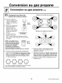
Adjust the pressure regulator, by the
following instructions:
• Unscrew the cap.
• Place your thumb against the flat side
of the spring retainer and press down
to remove the retainer.
• Carefully look at the spring retainer to
locate the NAT or LP position.
CAP GASKET
\
/ -t I sPRING
/ El [-7 L.P./PROPANE
NAT.
POSITION _ .......................... :'_----:L POSITION
PRESSURE REGULATOR
• Turn the spring retainer over so that
LP is showing on the bottom.
• Snap the retainer back into position.
13 continued on following page

LP Conversion
Making the LP Conversion cont.
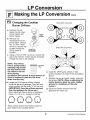
Changing the Cooktop
Burner Orifices:
a. Remove the top
grates, burner caps,
burner heads and
burner bases.
b. Remove the
electrodes from the
burner base. Using a
No. 15 "Torx" head
driver bit, remove the
screws holding the
burner base in
position.
C.
V REMOVE
I THIS
ORIFICE SPUD
LOCATED THRU
THIS OPENING
Using a 7mm or 9/32" nut driver, remove the
top burner orifices. These may be accessed
through the hole in the cooktop.
NOTE: The orifices
have a spring loaded _--_ _RETAINER
retaining ring around RJ.G
the hex head to hold
the orifice in the nut
driver during
installation and removal. A slight amount of
force is required to push the nut driver
down over the ring.
d. Locate the LP/Propane orifices shipped
inside the literature package. They will have
a digit number and the letter "L" on the side.
(IMPORTANT: Save the orifices removed
from the appliance for future use.)
Each orifice will show a series of engraved
marks, (I, II, III or X ), located on the top.
OOOO
Units with 4 burners
Units with 5 burners
e. Install the LP/Propane orifices in their
precise locations as noted in the illustrations
above.
f. Replace the burner bases, heads, caps and
top grates. (NOTE: When re-attaching the
burner bases to glass top units, tighten
screws to a maximum of 10in.-Ibs
torque.)
g. Save the orifices removed from the
appliance for future use.
These marks denote the precise location of
each orifice to the cooktop burner.
14 continued on following page

LP Conversion
Making the LP Conversion cont.
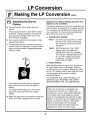
Adjusting the Burner
Flames
a. Turn all burners full on and check the
flames.
They should be blue in color with no trace
of yellow. Foreign particles in the gas line
may cause an orange flame at first, but
this will soon disappear.
b. Turn control knob to the low position while
observing the flame.
c. To make adjustments, remove the control
knobs. Insert a screwdriver through access
hole in the valve switch. Engage adjustment
screw in valve.
• If the flames were too small or fluttered,
open the valve more than the original
setting.
• If the flames blew away from the burner,
close the valve more than the original
setting.
d. Make the adjustment by slowing turning the
screw until flame appearance is correct.
Adjust the low flame setting using the valve
bypass screw as follows:
Low setting adjustments must be made with two
other burners in operation on a medium setting.
This prevents the low flame from being set too
low, resulting in the flame being extinguished
when other burners are turned on.
e. Testing
Test 1 -
flame stability:
Turn the knob from "HI" to "LOW"
quickly. If the "LOW" flame goes
out, increase the flame size and
test again.
Test 2 - With the burner on the "LOW"
setting, open and close the
cabinet door under the cooktop.
If the flame is extinguished by the
air currents created by the door
movement, increase the flame
height and test again.
Flame recheck:f,
After the adjustment is made, turn all burners
off. Ignite each burner individually. Observe
the flame at the "HI" position. Rotate the valve
to the "LO" position and be sure that the flame
size decreases as the valve is rotated
counterclockwise.
TO CONVERT THE COOKTOP BACK TO
NATURAL GAS, REVERSE THE STEPS
UNDER MAKING THE LP CONVERSION.
Once the conversion is complete and
checked ok, fill out the LP sticker and
include your name, organization and date
conversion was made. Apply the sticker
near the cooktop gas inlet opening to alert
others in the future that this appliance has
been converted to LP gas. If converting
back to natural gas from LP, please
remove the sticker so others know the
appliance is set to use natural gas.
15

NOTES
16

Instructions
d'installation
Table de cuisson scell_e au
gaz de 91 cm (36")
JGP628, JGP962, JGP963, ZGU36
Questions? Appelez le Centre de reponse GE au 800.626.2000 ou visitez
notre site Web b I'adresse • www.electromenagersge.ca
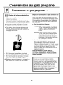
MISE EN GARDE : Avant de commencer, lisez
attentivement la totalitd de ces instructions.
• IMPORTANT--Conservez ces instructions
pour votre inspecteur local.
• IMPORTANT--Respectez toutes les
ordonnances et les codes Iocaux.
• Note a I'installateur : Assurez-vous de
laissez ces instructions au consommateur.
• Note au consommateur--Conservez ces
instructions pour rdfdrence future.
• Note--Cet appareil coit _tre bien mis & la terre.
• IMPORTANT : Vous devez verifier que cet
appareil n'a pas de fuite conformement aux
instructions du fabricant.
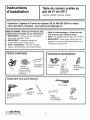
PIECES COMPRISES
2 Supports
Bandes de fixation
2 vis de mousse
(Pour les modeles
& surface en verre
seulement)
MATI_RIAUX NI:!:CESSAIRES
Raccords de
tuyaux
J
Agent de
scellement
de tuyau
Robinet
d'alimentation
de gaz
Outils dont vous aurez besoins
Perceuse &main ou
electrique et foret
de 1/8"
Tournevis
Phillips
\
Crayon
Cle & tuyau
Regle
ordinaire ou
de verification
Scie
sauteuse
229c4053P522
31-10539 (08-02 JR)

Instructions d'installation
f f
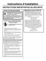
INSTRUCTIONS IMPORTANTES DE SECURITE
POUR VOTRE SI CURITI
Avertissement!! Si vous ne suivez
pas exactement les instructions de
ce manuel, vous risquez
d'occasionner un incendie, une explosion
ou une fuite de gaz, qui peuvent provoquer
des dommages materiels, des blessures
corporelles ou la mort.
Ne conservez pas ou n'utilisez jamais d'essence
ou d'autres liquides ou vapeurs inflammables
proximitd de cet appareil ou de tout
autre appareil mdnager!
CI QUE VOUS DEVEZ FAIRE SI VOUS
SENTEZ LE GAZ :
N'essayez jamais d'allumer un appareil
electrom6nager. Ne touchez & aucun commutateur
d'_lectricit_, n'utilisez jamais un t_l_phone dans votre
b&timent.
• Appelez imm_diatement votre fournisseur de gaz &
I'aide du t61_phoned'un voisin. Suivez les instructions
de votre fournisseur de gaz.
• Si vous ne pouvez pas entrer en communication avec
votre fournisseur de gaz, appelez les pompiers.
L'installation et service de votre table de cuisson doivent
_tre faites par un installateur qualifi_, un technicien de
service ou votre fournisseur de gaz.
BESOINS D'I LECTRICITI
Cet appareil dolt _tre mis _ la terre. Verifiez les
codes Iocaux qui s'appliquent clans votre region. Si
aucun code local ne s'applique, conformez-vous au
National Electrical Code, ANSI NFPA N° 70 Derniere
edition. Pour de plus amples renseignements, ecrivez
& I'adresse suivante:
National Fire Protection Association
Batterymarch Park
Quincy, MA 02269
Assurez-vous que I'installation de cette table de
cuisson clans une maison mobile se conforme & la
Manufactured Home Construction and Safety
Standard, Title 24 CFR, Part 3280. Si cette norme ne
s'applique pas, vous devez vous conformer & la
norme Standard for Manufactured Home Installations,
Sites and Communities et ANSI/NFPA 501A, ou aux
codes Iocaux. Vous pouvez obtenir un exemplaire de
la norme federale en ecrivant & I'adresse suivante :
Office of Mobile Home Standards
HUD Building
451 7th Street, S.W.
Washington, D.C. 24010
La conception de votre table de cuisson a ete approuve
par I'ACNOR International. Vous trouverez des
precautions 6 prendre en matiere de securite clans votre
Guide d'utilisation et de soins. Lisez-les attentivement.
L'installation de votre table de cuisson dolt se
conformer aux codes Iocaux ou, en I'absence de codes
Iocaux, au National Fuel Gas Code, ANSI Z223.1
Derni_re _dition.
• Assurez-vous que votre table de cuisson soit bien
install_e par un installateur qualifi_ ou un technicien
de service.
• Pour _liminer tout mouvement corporel au dessus des
brQleursde votre table de cuisson, _vitez de placer des
armoires de cuisine au dessus des brQleurs.
• N'installez jamais votre appareil pres d'une porte d'entr_e
ou & un emplacement oQun courant d'air peut g_ner son
usage.
2

Instructions d'installation
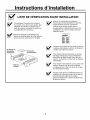
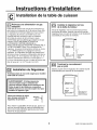
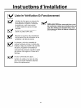
LISTE DE VITRIFICATION AVANT INSTALLATION
[_ Pour preparer I'ouverture de la surface I_"
de cuisson, vous devez vous assurer que
Hnterieur de I'armoire ne touche pas la
table de cuisson (consultez la section sur
la preparation de I'ouverture).
Enlevez les instructions d'installation
de la trousse de documentation et lisez-les
soigneusement avant de commencer.
Assurez-vous de bien ranger toute la
documentation, I'utillisation et les soins, les
installations, etc. dans un endroit sOrpour
reference future.
Retirez les materiaux d'emballage et la
trousse de documentation de votre table de
cuisson avant de commencer & Hnstaller.
Emballage
en
_-_-_ Trousse de
mousse de
polystyrene documentation
Assurez-vous d'avoir tous les outils et tousles
materaux necessaires avant de commencer
installer votre table de cuisson.
Votre maison doit _tre alimentee en courant
electrique adequat pour vous permettre de
bien utiliser en toute secuite votre table de
cuisson. (Consultez la section sur les besoins
d'electricite).
Pour installer votre table de cuisson dans votre
maison, assurez-vous de vous conformer
scrupuleusement a tousles codes et & toutes
les ordonnances locales.
Assurez-vous que les rev_tements de mur, le
comptoir et les armoires autour de la table de
cuisson puissent supporter la chaleur
[pouvant atteindre 93°0 (200°F)] produite par
la table de cuisson.
3

Instructions d'installation
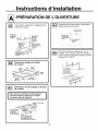
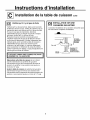
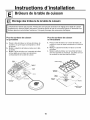
PREPARATION DE L'OUVERTURE
Vous devez respecter les degagementsminimaux suivant •
¢ompTolr a la
sui'face
en non
Degagement lain,
de 15 cm (6")
dL=coupage
, au tour de
cOtL=e droite
de I'apparell
Hauteur rain de 45 cm
(18") du comptoir e
I'armoire ]a plus proche
de chaque c6te
de Pappareil
de 10 cm
de ]'appareil
Profondeur max
de 33cm (,13")
des armolres en
surplomb non
protegees
Dimensions totales de la table
de cuisson
53cm
91cm .,....-._l-,_,,_ t_l"_
136"'1 _ '-- '
48cm
--._J/ (33 11/16")
(18 7/8")
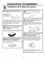
Dimensions du decoupage de la table
de cuisson
il Pour assurer la justesse du d_coupage, il Ill
vaut mieux faire un gabarit pour couper
I'ouverture dans le comptoir.
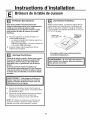
Emplacement recommande de I'alimentation
de gaz & partir du mur arriere.
2.5 cm (1") rain
du mur arriere
()
Emplacement
recommand_
de I'alimentation
de gaz _ Du decoupage
la ligne du
centre
Assurez-vous que les rev_tements mur, le
comptoir et les armoires autour de la table de
cuisson puissent supporter la chaleur (pouvant
atteindre 93°C (200°F).
le comptoir doivent
pouvoir supporter
une cha]eur pouvant
atleindre
largeur du d_coupage
48.5 cm
f' _-4_. (33 7/8 po) _16 15/16")
Distance min de "'_ ongueur du _ _ "
5.7 cm (2 1/4") de d_c u_u_u_u_u_u_u_u_u_u_a_e_-
decoupage / _ I _- _ I
au mur derriere / I _ _1 r
la table de cuisson -- _r- _
6.4 cm
(2 1/2") Distance min,
de I'arr_,te avant du
decoupage de I'arr_,te
avant de la table de cuisson
4
Page is loading ...
Page is loading ...
Page is loading ...
Page is loading ...
Page is loading ...
Page is loading ...
Page is loading ...
Page is loading ...
Page is loading ...
Page is loading ...
Page is loading ...
Page is loading ...
-
 1
1
-
 2
2
-
 3
3
-
 4
4
-
 5
5
-
 6
6
-
 7
7
-
 8
8
-
 9
9
-
 10
10
-
 11
11
-
 12
12
-
 13
13
-
 14
14
-
 15
15
-
 16
16
-
 17
17
-
 18
18
-
 19
19
-
 20
20
-
 21
21
-
 22
22
-
 23
23
-
 24
24
-
 25
25
-
 26
26
-
 27
27
-
 28
28
-
 29
29
-
 30
30
-
 31
31
-
 32
32


GE ZGU36GGSD1SS Installation guide
- Type
- Installation guide
- This manual is also suitable for
Ask a question and I''ll find the answer in the document
Finding information in a document is now easier with AI
in other languages
- français: GE ZGU36GGSD1SS Guide d'installation
Related papers
-
GE JGP945WEK2WW Installation guide
-
-
-
-
-
GE Profile JGP330BEKBB - 30" Gas Cooktop User manual
-
-
-
-
Other documents
-
LG MFL62725501 User manual
-
Bosch Benchmark NGM8057UC Installation guide
-
Kenmore 91132355590 Installation guide
-
Bosch NGM8657UC Installation guide
-
LG LSCG307ST Installation guide
-
IKEA ICS500VB0 Installation guide
-
Electrolux E36GC70FSS3 Installation guide
-
Frigidaire FFGC3015LSC Installation guide
-
Electrolux EW36GC55GB1 Installation guide
-
Frigidaire FFGC3025LWC Installation guide