Page is loading ...

IMPORTANT: PLEASE READ THESE INSTRUCTIONS CAREFULLY TO ENSURE THE
SAFE AND EFFECTIVE USE OF THIS PRODUCT.
INSTRUCTIONS
These instructions accompanying the product are the original instructions. This document is part of the product, keep
it for the life of the product passing it on to any subsequent holder of the product. Read all these instructions before
assembling, operating or maintaining this product.
This manual has been compiled by Draper Tools describing the purpose for which the product has been designed,
and contains all the necessary information to ensure its correct and safe use. By following all the general safety
instructions contained in this manual, it will ensure both product and operator safety, together with longer life of the
product itself.
AlI photographs and drawings in this manual are supplied by Draper Tools to help illustrate the operation of the
product.
Whilst every effort has been made to ensure the accuracy of information contained in this manual, the Draper Tools
policy of continuous improvement determines the right to make modifications without prior warning.
6-30V/D.C.
DIAGNOSTIC
PROBE
16422

1. TITLE PAGE
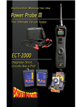
1.1 INTRODUCTION:
USER MANUAL FOR:
6-30V/D.C. DIAGNOSTIC PROBE
Stock no. 16422
Part no. DP101.
1.2 REVISIONS:
As our user manuals are continually updated, users should make sure that they use the very latest
version.
Downloads are available from: http://www.drapertools.com/manuals
DRAPER TOOLS LIMITED WEBSITE: drapertools.com
HURSLEY ROAD PRODUCT HELPLINE: +44 (0) 23 8049 4344
CHANDLER’S FORD GENERAL FAX: +44 (0) 23 8026 0784
EASTLEIGH
HAMPSHIRE
SO53 1YF
UK
1.3 UNDERSTANDING THIS MANUALS SAFETY CONTENT:
WARNING! Information that draws attention to the risk of injury or death.
CAUTION! Information that draws attention to the risk of damage to the product or
surroundings.
1.4 COPYRIGHT © NOTICE:
Copyright © Draper Tools Limited.
Permission is granted to reproduce this publication for personal & educational use only.
Commercial copying, redistribution, hiring or lending is prohibited.
No part of this publication may be stored in a retrieval system or transmitted in any other form or
means without written permission from Draper Tools Limited.
In all cases this copyright notice must remain intact.
Date first published January 2016

3
2. CONTENTS
2.1 CONTENTS
Page content
Page
1 TITLE PAGE
1.1 INTRODUCTION .......................................................................................................... 2
1.2 REVISION HISTORY.................................................................................................... 2
1.3 UNDERSTANDING THIS MANUAL ............................................................................. 2
1.4 COPYRIGHT NOTICE .................................................................................................. 2
2 CONTENTS
2.1 CONTENTS ..................................................................................................................3
3 GUARANTEE
3.1 GUARANTEE................................................................................................................ 4
4 INTRODUCTION
4.1 SCOPE.......................................................................................................................... 5
4.2 SPECIFICATION........................................................................................................... 5
4.3 HANDLING & STORAGE.............................................................................................. 5
5 HEALTH & SAFETY INFORMATION
5.1 SAFETY PRECAUTIONS AND WARNINGS................................................................ 6
6 TECHNICAL DESCRIPTION
6.1 IDENTIFICATION.......................................................................................................... 7
7 UNPACKING & CHECKING
7.1 PACKAGING.................................................................................................................8
7.2 WHAT´S IN THE BOX?................................................................................................. 8
8 OPERATING INSTRUCTIONS
8.1 GENERAL DESCRIPTION ........................................................................................... 9
8.2 POWER......................................................................................................................... 9
8.3 QUICK SELF-TEST ...................................................................................................... 9
8.4 AUTO CIRCUIT BREAKER ........................................................................................ 10
8.5 WORK MODE ............................................................................................................. 10
8.6 DC VOLTAGE............................................................................................................. 10
8.7 FREQUENCY.............................................................................................................. 11
8.8 RESISTANCE ............................................................................................................. 12
8.9 DIODE......................................................................................................................... 13
9 TEST APPLICATIONS
9.1 VOLTAGE & POLARITY TESTING ............................................................................ 14
9.2 CONTINUITY TESTING.............................................................................................. 14
9.3 SIGNAL CIRCUIT TESTING....................................................................................... 15
9.4 ACTIVATING COMPONENTS IN YOUR HAND......................................................... 16
9.5 TESTING TRAILER LIGHTS AND CONNECTIONS .................................................. 16
9.6 ACTIVATING COMPONENTS IN THE VEHICLE....................................................... 17
9.7 ACTIVATING COMPONENTS W/GROUND .............................................................. 17
9.8 CHECKING FOR BAD GROUND CONTACTS .......................................................... 18
9.9 FOLLOWING & LOCATING SHORT CIRCUITS ........................................................ 18
9.10 RED/GREEN POLARITY LED .................................................................................... 18
10 EXPLANATION OF SYMBOLS
10.1 EXPLANATION OF SYMBOLS................................................................................... 19
11 DISPOSAL
11.1 DISPOSAL ................................................................................................................. 20
DECLARATION OF CONFORMITY.......................................................................................ENCLOSED

4
3. GUARANTEE
3.1 GUARANTEE
Draper tools have been carefully tested and inspected before shipment and are guaranteed to be
free from defective materials and workmanship.
Should the tool develop a fault, please return the complete tool to your nearest distributor or
contact Draper Tools Limited, Chandler's Ford, Eastleigh, Hampshire, SO53 1YF. England.
Telephone Sales Desk: (023) 8049 4333 or Product Helpline (023) 8049 4344.
A proof of purchase must be provided with the tool.
If upon inspection it is found that the fault occurring is due to defective materials or workmanship,
repairs will be carried out free of charge. This guarantee period covering parts/labour is 12 months
from the date of purchase except where tools are hired out when the guarantee period is 90 days
from the date of purchase. This guarantee does not apply to normal wear and tear, nor does it
cover any damage caused by misuse, careless or unsafe handling, alterations, accidents, or
repairs attempted or made by any personnel other than the authorised Draper warranty repair
agent.
Note: If the tool is found not to be within the terms of warranty, repairs and carriage charges will be
quoted and made accordingly.
This guarantee applies in lieu of any other guarantee expressed or implied and variations of its
terms are not authorised.
Your Draper guarantee is not effective unless you can produce upon request a dated receipt or
invoice to verify your proof of purchase within the guarantee period.
Please note that this guarantee is an additional benefit and does not affect your statutory rights.
Draper Tools Limited.

5
4. INTRODUCTION
4.1 SCOPE
This electrical tester reduces diagnostic time in all 6 to 30 volt vehicle electrical systems. Simply
hook-up the tool to the vehicle’s battery.
4.2 SPECIFICATION
Stock no. ............................................................................................................................16422
Part no. ............................................................................................................................ DP101
DC voltage range................................................................................................... 0-65V +1 digit
Resistance range........................................................................................................... 0-100KΩ
Frequency response of tone passes through ......................................................... 0Hz to 10Khz
Rating current................................................................................................................ 1-10Amp
Testing standard
100% current................................................................................................Hold >1 hour
150% current.............................................................................................trip in one hour
200% current..................................................................................... trip in 3-30 seconds
300% current................................................................................. trip in 0.5-4.0 seconds
Display................................................................................... TFT colour display (160 x 128 dpi)
Operating Temperature...........................................................................0 to 60ºC (32 to 140 F°)
Storage Temperature......................................................................... -40 to 70ºC (-40 to 185 F°)
External Power................................................12.0 or 24.0V power provided via vehicle battery
Dimensions(L*W*H)...............................................................................................178*47*28mm
Weight (nett).......................................................................................................................0.1kg
4.3 HANDLING & STORAGE
Although this machine is small in size, care must still be taken when handling. Dropping this
machine will have an effect on the accuracy. This machine is not a toy and must be respected.
The environment will have a negative result on its operation if you are not careful. If the air is
damp, components will rust. If the machine is unprotected from dust and debris; components will
become clogged: And if not cleaned and maintained correctly or regularly the machine will not
perform at its best.

6
5. HEALTH & SAFETY INFORMATION
5.1 SAFETY PRECAUTIONS AND WARNINGS
To prevent personal injury or damage to vehicles and/or the test tool, read this instruction manual first and
observe the following safety precautions at a minimum whenever working on a vehicle:
• Always perform automotive testing in a safe environment;
• Wear safety eye protection that meets ANSI standards;
• Keep clothing, hair, hands, tools, test equipment, etc. away from all moving or hot engine parts;
• Operate the vehicle in a well ventilated work area: Exhaust gases are poisonous
• Put blocks in front of the drive wheels and never leave the vehicle unattended while running tests.
Use extreme caution when working around the ignition coil, distributor cap, ignition wires and spark plugs.
These components create hazardous voltages when the engine is running.
• Put the transmission in PARK (for automatic transmission) or NEUTRAL (for manual transmission) and
make sure the parking brake is engaged.
• Keep a fire extinguisher suitable for gasoline/chemical/electrical fires nearby.
• Don’t connect or disconnect any test equipment while the ignition is on or the engine is running.
• Keep the tool dry, clean, free from oil/water or grease. Use a mild detergent on a clean cloth to clean the
outside of the test tool, when necessary.
• When the power switch in the tool is depressed battery current /voltage is conducted directly to the tip which
may cause sparks when contacting ground or certain circuits. Therefore the tool should NOT be used around
flammables such as gasoline or its vapours. The spark of an energized tool could ignite these vapours. Use
the same caution as you would when using an arc welder.

7
6. TECHNICAL DESCRIPTION
6.1 IDENTIFICATION
Probe Tip connection
Work Lights
Red Polarity Indicator
Green Polarity Indicator
LCD Display
Power switch
Mode button
Auxiliary ground lead
Power connection

8
12V adaptor.
Battery hookup clips.
Probe tips.
Extension cable.
7. UNPACKING & CHECKING
7.1 PACKAGING
Carefully remove the product from the packaging and examine it for any sign of damage that may
have happened during shipping. Lay the contents out and check them against the parts shown
below. If any part is damaged or missing; please contact the Draper Helpline (the telephone
number appears on the Title page) and do not attempt to use the tool.
The packaging material should be retained at least during the guarantee period: in case the
machine needs to be returned for repair.
Warning! Some of the packaging materials used may be harmful to children. Do not leave any of
these materials in the reach of children.
If any of the packaging is to be thrown away, make sure they are disposed of correctly; according
to local regulations.
7.2 WHAT´S IN THE BOX?
As well as the product; there are several parts not fitted or attached to it.

9
8.1 GENERAL DESCRIPTION
The tool is ideal for reducing diagnostic time in all 6 to 30 volt vehicle electrical systems. After a
simple hook-up of the tool to the vehicle’s battery, you can:
• Determine at a glance if a circuit is positive, negative, or open without having to reconnect clips
from one battery pole to another.
• Test for continuity with its built-in auxiliary ground lead.
• By depressing the power switch, conduct a positive or negative battery current to the probe tip
for testing the function of an electrical component.
• Test for poor ground contacts instantly without performing voltage drop tests. The tool is also
short - circuit protected; its internal circuit breaker will trip if it becomes overloaded.
• Follow and locate short circuits without wasting fuses. The tool’s long cable allows you to test
along the entire length of the vehicle without constantly searching for suitable vehicle grounds.
8.2 POWER
The tool is powered via the vehicle battery. Connect the RED battery clamp to the POSITIVE
terminal of the vehicle’s battery, and the BLACK clamp to the NEGATIVE terminal. When the tool
is first connected to a battery (power source), it will sound a beep and the Work Lights will be on
to illuminate the test area of the probe tip.
8. OPERATING INSTRUCTIONS
8.3 QUICK SELF-TEST - FIG. 1
Before you test a circuit or component, be sure your
tool is in good order by doing a quick self-test.
With the tool connected, perform a quick self-test.
The power switch is a momentary rocker switch
located on the tool’s body. Flanking the switch are
positive and negative markings.
Press the Power Switch forward to activate the tip
with a positive voltage. The Red LED should light
and the LCD display will read the battery voltage. A
beep tone will sound. Let go of the power switch
and the LED will turn off and the tone will cease.
Press the Power Switch rearward to activate the tip
with a negative voltage. The Green LED should light
and the LCD display will read the 0.0V (ground). A
beep tone will sound. Let go of the power switch
and the LED will turn off and the tone will cease.
Your tool is working correctly and is now ready for
use.
IMPORTANT: When powering-up components, you
can increase the life of power switch in the tool if
you first press the switch, then contact the tip to the
component. The arcing will take place at the tip
instead of the contacts of the switch.
FIG.1

10
8. OPERATING INSTRUCTIONS
8.4 AUTO CIRCUIT BREAKER - FIG. 2
The tool is short-circuiting protected. Its internal circuit
breaker will trip if it becomes overloaded. The circuit
breaker is a valuable test tool as well as a safety measure
to protect the tool from overload.
When circuit breaker tripped, the LCD will display as Fig.2.
All other functions of the tool are still active, which means
you can still probe a circuit and observe the voltage
reading. When the circuit breaker is tripped, the tool will
NOT be able to conduct battery current to the tip even
when the power switch is pressed. Intentionally tripping the
breaker and using the tool to probe can be considered an
added precaution against accidental pressing of the power
switch.
8.5 WORK MODE
There are four modes to diagnose the electrical systems, which can be accessed by depressing
the Mode Button and cycling through each one.
8.6 DC VOLTAGE - FIGS. 3 - 4
While the tool in this mode, contact the probe tip to a circuit, then the LCD display will read the DC
voltage with a resolution of 0.1 volt.
FIG.4
View of screen
FIG.3
FIG.2

11
8. OPERATING INSTRUCTIONS
8.7 FREQUENCY - FIGS. 5 - 7
While the tool in this mode, contact the probe tip to a
circuit, then the LCD display will read the Max. Voltage, the
Min. voltage and frequency.
FIG.5
View of screen View of screen
FIG.6 FIG.7

12
8. OPERATING INSTRUCTIONS
8.8 RESISTANCE - FIGS. 8 - 9
While the tool in this mode, contact the probe tip to a
circuit, then the LCD display will read the resistance
between the tip and auxiliary ground lead.
FIG.8
Application
FIG.9

13
8. OPERATING INSTRUCTIONS
8.9 DIODE - FIGS. 10 - 11
The diode work mode is to test the polarity of PN junction of
diode. Contact the probe and the black alligator clip to two
electrodes of diode. After getting the result, exchange the
position of probe and the black alligator clip to get the other
result. One of the results will have relatively larger
resistance value or infinite value (Reverse Conduction), the
other one will have smaller resistance value. (Forward
conduction) In the measurement result with smaller
resistance value, it is the anode that the probe is contacted
to; the black alligator clip is contacted to the cathode of
diode. If the resistance value in both measurements is
shown as “0.0Ω”, it means the diode is broken down and
damaged.
View of screen
FIG.11
FIG.10

14
9. TEST APPLICATIONS
9.1 VOLTAGE & POLARITY TESTING - FIGS. 12 - 13
While the tool is in DC Voltage mode, contact the probe tip to a POSITIVE circuit. The red LED
will light and the LCD displays the voltage with a resolution of 0.1V. A beep tone will sound.
If contact the probe tip to a NEGATIVE circuit, the green LED will light and the LCD displays the
voltage with a resolution of 0.1V. A beep tone will sound.
If contact the probe tip to an OPEN circuit, neither of the LED will light.
FIG.12
FIG.4
9.2 CONTINUITY TESTING - FIGS. 14 - 15
While the tool is in Resistance mode, using the probe tip with chassis is ground or the auxiliary
ground lead, continuity can be tested on wires and components attached or disconnected from the
vehicle’s electrical system.
When the probe tip is contacting a good ground, the LCD will indicate “0.0Ω” and green LED will
be on. A beep tone will sound.
FIG.12

15
9. TEST APPLICATIONS
In other cases, the LCD only indicates the resistance
value.
If the resistance value is greater than 100 kΩ, the LCD will show “0L”. There is also another way
to prove continuity of connections to ground or battery. Power up the connection by using the
power switch. If the circuit breaker trips you know that you have a good solid low resistance
connection.
NOTE: You can use the probe tip to pierce the plastic insulation on a wire. This means that you
can test the circuit without disconnecting anything.
9.3 SIGNAL CIRCUIT TESTING - FIG. 16
Once you extract a DTC from the vehicle and realize that
trouble-shooting begins with some kind of sensor circuit,
there is a quick test you can perform to verify the code.
Testing your sensor is easy while using the tool.
For example, you suspect there is a problem with your
M.A.P. Sensor circuit, then follows the procedure
involved with testing this sensor:
• Set the tool in AC Voltage mode, using the probe tip
with chassis ground or the auxiliary ground lead.
• Connect vacuum pump to MAP sensor.
• Contact the probe tip to the MAP sensor positive
terminal and observe the LCD readings which should
be a sine wave in normal condition.
• Apply vacuum.
• Release vacuum and observe the LCD readings.
If the LCD readings are abnormal, there is a problem
with this sensor.
FIG.16
FIG.15

16
9. TEST APPLICATIONS
9.4 ACTIVATING COMPONENTS IN YOUR HAND - FIG. 17
While the tool is in DC Voltage mode, by using the probe tip in connection with the auxiliary ground
lead, components can be activated right in your hand, thereby testing their functions.
Connect the auxiliary ground lead to the negative terminal or ground side of the component being
tested. Then contact the probe tip to the positive terminal of the component, the green LED should
light, indicating continuity through the component. While keeping an eye on the green LED, quickly
press and release the power switch forward. If the green LED went out and the red LED came on,
you may proceed with further activation. Rock the power switch forward and hold it down to
provide power to your component. With the power switch rocked forward, power will flow from the
positive lead on the battery into the probe tip, through the tip into the component’s positive
terminal, into the component and out of the component, through the auxiliary ground lead and back
into the tool, and back to the vehicle’s battery’s ground.
9.5 TESTING TRAILER LIGHTS AND
CONNECTIONS - FIG. 18
While the tool in DC Voltage mode, clip the auxiliary
ground lead to the trailer ground, probe the contacts at
the jack and then apply voltage to the probe tip. This
lets you check the function and orientation of the
connector and trailer lights.
If the circuit breaker tripped, that contact is likely a
ground. Reset the circuit breaker by letting it cool down
for 15 seconds.
• Press the power switch forward to activate the bulb.
• Contact the tip to the positive terminal of the bulb
• Connect the negative auxiliary clip.
If the green LED went off at that instant or if the circuit breaker
tripped and the tool has been overloaded. This could happen
for the following reasons:
• The contact you are probing is a direct ground or negative
voltage.
• The component you are testing is short-circuited.
• The component is a very high current component (i.e.,
starter motor).
If the circuit breaker is tripped, reset it by waiting for it to cool
down (15 sec.)
FIG.17
FIG.18

17
FIG.19
9. TEST APPLICATIONS
9.6 ACTIVATING COMPONENTS IN THE VEHICLE - FIG. 19
While the tool in DC Voltage mode, contact the probe tip to the positive terminal of the component,
the green LED should light, indicating continuity to ground. While observing the green LED, quickly
depress and release the power switch forward. If the green LED went out and the red LED came
on, you may proceed with further activation. If the green LED went off at that instant or if the circuit
breaker tripped, the tool has been overloaded.
This could happen for the following reasons:
• The contact you are probing is a direct ground.
• The component you are testing is short-circuited.
• The component is a very high current component
(i.e., starter motor).
If the circuit breaker is tripped, reset it by waiting for
it to cool down (15 sec.).
WARNING: Haphazardly applying voltage to certain
circuits can cause damage to a vehicle’s electronic
components. Therefore, it is strongly advised to use
the vehicle manufacturer’s schematic and diagnosing
procedure while testing.
NOTE: When powering up components, you can
increase the life of power switch if you first press the
switch, then contact the tip to the component. The
arcing will take place at the tip instead of the contacts
of the switch.
9.7 ACTIVATING COMPONENTS
W/GROUND - FIG. 20
While the tool in DC Voltage mode, contact the probe tip
to the negative terminal of the component, the red LED
should light. While observing the red LED, quickly
depress and release the power switch rearward. If the red
LED went out and the green LED came on, you may
proceed with further activation. If the green LED went off
at that instant or if the circuit breaker tripped, the tool has
been overloaded. This could happen for the following
reasons:
• The contact you are probing is a direct positive voltage.
• The component you are testing is short-circuited.
• The component is a very high current component (i.e.,
starter motor).
If the circuit breaker is tripped, reset it by waiting for it to cool down (15 sec.).
NOTE: Is the Tester computer and air bag safe?
The tool LED and LCD pull no more than 1 milliamp of current, therefore when using it as a test
light or multimeter it is computer and air bag safe. However, pressing the power switch is a
different story. When you press the switch forward, you are conducting full battery current to the tip
of the probe. There is a nice safety feature built into the tool. Simply connect the extra ground lead
to the tool and press the power switch forward until it trips the circuit breaker. This will prevent
power from going to the tip but still allow you to use the tool as a multi-meter. When you are away
from computer components, simple press the reset button and you are ready to power up again.
FIG.20

18
9. TEST APPLICATIONS
9.8 CHECKING FOR BAD GROUND CONTACTS
Probe the suspected ground wire or contact with the probe tip.
Observe the green LED. Depress the power switch forward then release. If the green LED went
out and the red LED came on, a beep will sound, this is not a true ground. If the circuit breaker
tripped, this circuit is more than likely a good ground. Keep in mind that high current components
such as starter motors will also trip the circuit breaker.
9.9 FOLLOWING & LOCATING SHORT CIRCUITS
In most cases a short circuit will appear by a fuse or a fusible link blowing or an electrical
protection device tripping (i.e., a circuit breaker). This is the best place to begin the search.
Remove the blown fuse from the fuse box.
Use the probe tip to activate and energize each of the fuse contacts. The contact which trips the
circuit breaker is the shorted circuit. Take note of this wire’s identification code or colour.
Follow the wire as far as you can along the wiring harness.
Here is an example for this application.
• If you are following a short in the brake light circuit, you may know that the wire must pass
through the wiring harness at the door sill. Locate the colour-coded wire in the harness and
expose it.
• Probe through the insulation with the probe tip, and depress the power switch forward to activate
and energize the wire.
If the circuit breaker tripped, you have verified the shorted wire. Cut the wire and energize each
end with the probe tip. The wire end which trips the circuit breaker again is the shorted circuit and it
will lead you to the shorted area.
Follow the wire in the shorted direction and repeat this process until the short is located.
9.10 RED/GREEN POLARITY LED
The Red/Green Polarity LED lights up when the probe tip voltage matches the battery voltage
within ±0.4 volts. It is added information that could be valuable to the technician.
If the circuit you are testing is not within a 0.4 volt (plus or minus) of supply voltage, you will see
the voltage reading on the LCD but you will not hear a tone or see a red or green LED. This tells
you either you have a voltage drop in excess of 0.8 volt from battery voltage or you are probing a
circuit that has an increase of a 0.8 volt or more over battery voltage. To determine battery voltage,
simply remove the tip from the circuit and press the power switch forward. Battery voltage will then
be displayed on the LCD. The difference between the battery voltage and what is read on the
circuit is either voltage drop or voltage increase. This allows you to determine a voltage drop
without running back to check the battery. It’s just another one of time saving feature the tool has.

19
10. EXPLANATION OF SYMBOLS
10.1 EXPLANATION OF SYMBOLS
For indoor use.
Do not expose to rain.
WEEE
Do not dispose of Waste Electrical
& Electronic Equipment in with
domestic rubbish
Warning!
Read instruction manuals before
operating and servicing this
equipment.

20
11. DISPOSAL
11.1 DISPOSAL
- At the end of the machine’s working life, or when it can no longer be repaired, ensure that it is
disposed of according to national regulations.
- Contact your local authority for details of collection schemes in your area.
In all circumstances:
• Do not dispose of power tools with domestic waste.
• Do not incinerate.
• Do not abandon in the environment.
• Do not dispose of WEEE*
as unsorted municipal waste.
* Waste Electrical & Electronic Equipment.
/