Page is loading ...

35 mm
35 mm INSIDE
50 mm
445 mm
463 mm
196.5 mm
70 mm
WOOD KNOB
Guide door is
the one that
closes towards
opening
CROSS SECTION AND FINISHING OPTIONS
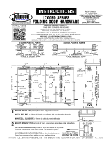
Instructions - 1700 Series - Folding Door Hardware
Bifold Door Installation Instructions
01 Track (1700+1710+1713)
01 Top Pivot (1701)
01 Roller Guide (1705)
01 Bottom Pivot (1707)
01 Jamb Bracket (1711)
01 Wrench (1712)
01
Aligner (1808)
01
Pivot/Guide Screws (A)
05 Track Screws (B)
01 Knob Screw (C)
02 Aligner Screws (D)
03 Jamb Bracket Screws (E)
Wood Knob (36)
06
PREPARE OPENING CAREFULLY: MAKE SURE CORNERS ARE SQUARE, HEADER IS LEVEL, AND JAMBS ARE STRAIGHT.
Before you start - Confirm Material Included In Hardware Pack:
STEP 1
STEP 2
STEP 3
STEP 4
STEP 5
STEP 6
STEP 7
Mount knob (36). See drawing on step 7.
Mark location of jamb bracket (1711) on jamb.
Fasten in place 1711 with one pan head screw
(part E). Proceed to next step.
Fasten pivot plates to top and bottom of doors as shown.
Hang doors: Make sure Track pivot lock (1710) is in the unlocked
position.
A) Fold doors and insert 1705 into track groove. Place 1701 into receptor
of 1710.
B) When firmly seated, slide tab lock toward pin. Door now should be
hanging from 1701.
C) Depress 1711 pivot socket arm and insert 1707. If no vertical adjustment
is needed, secure 1711 with other 2 screws.
D) Use 1712 wrench for horizontal adjustment of 1710 and 1711.
Adjust snubber (1713). Close doors, slide 1713
until it touches 1705. Open doors, move 1713
1/8” (3mm) closer to 1705 and tighten. Doors
should “snap” shut yet open easily by a slight pull
on the knob.
A
E
B
D
1707
1705
36
1808
1700
1713
1710
C
1701
1711
Mount track 3/4 (19mm) from front edge
of head jamb.
1712
A
B
C
Mount aligner (1808) on back side of lead doors (4 doors
only).
D
Left hand swing
Top of door
Bottom of door
Jamb edgeJamb edge
Door
height
Left or right
2 door width + 9/16”
4 door width + 13/16”
1700 Series
Note: Doors not to scale.
D
O
OR
H
E
I
G
H
T P
L
U
S
2’’
3/4’’ (19mm)
TIRADOR
La puerta
guía es la que
cierra hacia la
abertura
CORTES TRANSVERSALES Y DIFERENTES TERMINACIONES
Instrucciones Para El Montaje - 1700 Series
Instrucciones para la Instalación de Puertas Plegables
01 Riel Superior (1700+1710+1713)
01 Pivote Superior (1701)
01 Pivote Superior con guía plástica (1705)
01 Pivote Inferior (1707)
01 Soporte de la Jamba (1711)
01 Llave de Tuercas (1712)
01 Alineador (1808)
01
Tornillos de Cabeza Plana (A)
05 Tornillos Cabeza Redonda para Riel (B)
01 Tornillo largo para el Tirador (C)
02 Tornillos Cabeza Redonda (D)
03 Tornillos para el Soporte de la jamba (E)
Tirador (36)
06
PREPARE LAS APERTURAS CON CUIDADO: ASEGÚRESE QUE LAS ESQUINAS ESTEN EN ESCUADRA, EL ENCABEZADOR ESTE NIVELADO Y LAS JAMBAS ESTEN ALINEADAS.
Antes de comenzar - :Asegúrese que los siguientesmateriales estén incluidosen el paquete de accesorios
PASO 1
PASO 2
PASO 3
PASO 4
PASO 5
PASO 6
PASO 7
Marque el sito del soporte de la jamba
(1711) en la jamba. Coloque el 1711 en su
lugar con un tornillo de cabeza plana
(pieza E). Prosiga con el paso siguiente.
Coloque las placas giratorias arriba y abajo de las puertas como se muestra.
Cuelgue las puertas Asegúrese que la cerradura giratoria del riel
(1710) esté en la posición abierta.
(A) Doble las puertas e inserte el 1705 en la ranura del riel. Coloque el
1701 en el receptor del 1710.
(B) Cuando está bien asentada, haga deslizar la aleta de ajuste hacia el
pasador. La puerta ahora debe estar colgada del 1701.
C) Oprime el brazo de la base del pivot 1711 e inserte el 1707. Si no
necesita ningún ajuste vertical, asegure el 1711 con 2 tornillos más.
(D) Use la llave de tuercas 1712 para el ajuste horizontal del 1710 y 1711.
Ajuste el freno amortiguador (1713). Cierre las
puertas, haga deslizar el 1713 hasta que toque
las puertas abiertas 1705, mueva el 1713 a 3mm
más cerca de 1705 y ajústelo. Las puertas deben
cerrarse con firmeza, pero deben abrirse fácilmente
jalando ligeramente la perilla.
A
E
B
D
1707
1705
36
1808
1700
1713
1710
C
1701
1711
Instale el riel a 19mm del borde de enfrente
del encabezador de jamba.
1712
A
B
C
Instale el alineador (1808) en el lado trasero de las puertas
delanteras (en los juegos de 4 puertas solamente).
D
Giro del lado izquierdo
Parte superior Puerta
Parte inferior de la puerta
Borde de la jambaBorde de la jamba
Altura de
la puerta
Izquierdo o Derecha
2* Ancho de la puerta + 15mm
4* Ancho de la puerta + 22mm
1700 Series
Instale el tirador (36). Vea dibujo en el Paso7.
3/4’’ (19mm)
ALTURA DE LA PUERTA + 50mm
Nota: Puertas no son a scala
3/4’’ (19mm)
/

