NordicTrack 510 EX User manual

Category
Fitness, gymnastics & weight training
Type
User manual
USER’S MANUAL
Serial Number
Decal (under frame)
www.nordictrack.com
CAUTION
Read all precautions and instruc-
tions in this manual before using
this equipment. Keep this manual
for future reference.
Model No. NTEL06011.0
Serial No.
Write the serial number in the space
above for reference.
QUESTIONS?
If you have questions, or if parts
are damaged or missing, DO NOT
CONTACT THE STORE; please
contact Customer Care.
IMPORTANT: Please register this
product (see the limited warranty
on the back cover of this manual)
before contacting Customer Care.
CALL TOLL-FREE:
1-800-TO-BE-FIT
(1-800- 862-3348)
Mon.–Fri., 6 a.m.–6 p.m. MT
Sat. 8 a.m.–4 p.m. MT
ON THE WEB:
www.nordictrackservice.com
2
NORDICTRACK is a registered trademark of ICON IP, Inc.
WARNING DECAL PLACEMENT
This drawing shows the location(s) of the warning
decal(s). If a decal is missing or illegible, see the
front cover of this manual and request a free
replacement decal. Apply the decal in the loca-
tion shown. Note: The decal(s) may not be shown
at actual size.
TABLE OF CONTENTS
WARNING DECAL PLACEMENT . . . . . . . . . . . . . . . . . . . . . . . . . . . . . . . . . . . . . . . . . . . . . . . . . . . . . . . . . . . . . . .2
IMPORTANT PRECAUTIONS . . . . . . . . . . . . . . . . . . . . . . . . . . . . . . . . . . . . . . . . . . . . . . . . . . . . . . . . . . . . . . . . . .3
BEFORE YOU BEGIN. . . . . . . . . . . . . . . . . . . . . . . . . . . . . . . . . . . . . . . . . . . . . . . . . . . . . . . . . . . . . . . . . . . . . . . .4
PART IDENTIFICATION CHART. . . . . . . . . . . . . . . . . . . . . . . . . . . . . . . . . . . . . . . . . . . . . . . . . . . . . . . . . . . . . . . .5
ASSEMBLY . . . . . . . . . . . . . . . . . . . . . . . . . . . . . . . . . . . . . . . . . . . . . . . . . . . . . . . . . . . . . . . . . . . . . . . . . . . . . . . .6
HOW TO USE THE ELLIPTICAL . . . . . . . . . . . . . . . . . . . . . . . . . . . . . . . . . . . . . . . . . . . . . . . . . . . . . . . . . . . . . .15
FCC INFORMATION . . . . . . . . . . . . . . . . . . . . . . . . . . . . . . . . . . . . . . . . . . . . . . . . . . . . . . . . . . . . . . . . . . . . . . . .23
MAINTENANCE AND TROUBLESHOOTING . . . . . . . . . . . . . . . . . . . . . . . . . . . . . . . . . . . . . . . . . . . . . . . . . . . .24
EXERCISE GUIDELINES . . . . . . . . . . . . . . . . . . . . . . . . . . . . . . . . . . . . . . . . . . . . . . . . . . . . . . . . . . . . . . . . . . . .26
PART LIST. . . . . . . . . . . . . . . . . . . . . . . . . . . . . . . . . . . . . . . . . . . . . . . . . . . . . . . . . . . . . . . . . . . . . . . . . . . . . . . .27
EXPLODED DRAWING. . . . . . . . . . . . . . . . . . . . . . . . . . . . . . . . . . . . . . . . . . . . . . . . . . . . . . . . . . . . . . . . . . . . . .29
ORDERING REPLACEMENT PARTS . . . . . . . . . . . . . . . . . . . . . . . . . . . . . . . . . . . . . . . . . . . . . . . . . . Back Cover
LIMITED WARRANTY. . . . . . . . . . . . . . . . . . . . . . . . . . . . . . . . . . . . . . . . . . . . . . . . . . . . . . . . . . . . . . . Back Cover
3
WARNING: To reduce the risk of serious injury, read all important precautions and
instructions in this manual and all warnings on your elliptical before using your elliptical. ICON
assumes no responsibility for personal injury or property damage sustained by or through the use of
this product.
1. Before beginning any exercise program,
consult your physician. This is especially
important for persons over age 35 or per-
sons with pre-existing health problems.
2. Use the elliptical only as described in this
manual.
3. It is the responsibility of the owner to ensure
that all users of the elliptical are adequately
informed of all precautions.
4. The elliptical is intended for home use only.
Do not use the elliptical in a commercial,
rental, or institutional setting.
5. Keep the elliptical indoors, away from mois-
ture and dust. Do not put the elliptical in a
garage or covered patio, or near water.
6. Place the elliptical on a level surface, with at
least 3 ft. (0.9 m) of clearance in the front and
rear of the elliptical and 2 ft. (0.6 m) on each
side. To protect the floor or carpet from dam-
age, place a mat under the elliptical.
7. Inspect and properly tighten all parts regu-
larly. Replace any worn parts immediately.
8. Keep children under age 12 and pets away
from the elliptical at all times.
9. The elliptical should not be used by persons
weighing more than 300 lbs. (136 kg).
10. Wear appropriate clothes while exercising;
do not wear loose clothes that could become
caught on the elliptical. Always wear athletic
shoes for foot protection while exercising.
11. Hold the handlebars or the upper body arms
when mounting, dismounting, or using the
elliptical.
12. The heart rate monitor is not a medical
device. Various factors may affect the accu-
racy of heart rate readings. The heart rate
monitor is intended only as an exercise aid
in determining heart rate trends in general.
13. The elliptical does not have a freewheel; the
pedals will continue to move until the fly-
wheel stops. Reduce your pedaling speed in
a controlled way.
14. Keep your back straight while using the ellip-
tical; do not arch your back.
15. Over exercising may result in serious injury
or death. If you feel faint or if you experience
pain while exercising, stop immediately and
cool down.
IMPORTANT PRECAUTIONS
4
BEFORE YOU BEGIN
Thank you for selecting the revolutionary
NORDICTRACK
®
E 5.5 elliptical. The E 5.5 elliptical
provides an impressive selection of features designed
to make your workouts at home more effective and
enjoyable.
For your benefit, read this manual carefully before
you use the elliptical. If you have questions after
reading this manual, please see the front cover of this
manual. To help us assist you, note the product model
number and serial number before contacting us. The
model number and the location of the serial number
decal are shown on the front cover of this manual.
Before reading further, please familiarize yourself with
the parts that are labeled in the drawing below.
Handlebar
Upper Body Arm
Console
Wheel
Adjustment Knob
Pedal
Storage Latch
Accessory Tray
Heart Rate Monitor
Handle
Leveling Foot
Disc
Length: 6 ft. 4 in. (193 cm)
Width: 2 ft. 2 in. (66 cm)
5
M8 Locknut
(105)–6
Wave Washer
(118)–2
M10 Split
Washer (128)–4
M8 x 23mm
x 1.5mm Washer
(126)–10
M6 x 12mm
Screw (111)–2
M8 x 45mm Button Bolt (104)–6
M4 x 16mm
Screw (93)–16
M8 Split Washer
(131)–6
M4 x 25mm
Screw (132)–2
M8 x 16mm
Screw (102)–18
M8 x 50mm
Button Screw (123)–6
M10 x 120mm Screw (100)–4
PART IDENTIFICATION CHART
Use the drawings below to identify the small parts needed for assembly. The number in parentheses below each
drawing is the key number of the part, from the PART LIST near the end of this manual. The number following the
key number is the quantity needed for assembly. Note: If a part is not in the hardware kit, check to see if it
has been preassembled. Extra parts may be included.
6
Assembly requires two persons.
Place all parts in a cleared area and remove the
packing materials. Do not dispose of the packing
materials until you complete all assembly steps.
To identify small parts, see page 5.
In addition to the included tool(s), assembly
requires the following tools:
one Phillips screwdriver
one rubber mallet
Assembly may be easier if you have your own set
of wrenches. To avoid damaging parts, do not use
power tools.
ASSEMBLY
2. Identify and orient the Front Stabilizer (3) as
shown.
While a second person lifts the Frame (1), attach
the Front Stabilizer (3) to the Frame with two
M10 x 120mm Screws (100) and two M10 Split
Washers (128).
1
3
1
100
128
1. Pull the Folding Frame (2) back until it locks
into position. Then, see HOW TO FOLD AND
UNFOLD THE ELLIPTICAL on page 15 and
unfold the elliptical.
Tip: It may be easier to perform this step with
the elliptical in the folded position.
Identify and orient the Rear Stabilizer (4) as
shown.
While a second person lifts the Folding Frame
(2), attach the Rear Stabilizer (4) to the Folding
Frame with two M10 x 120mm Screws (100) and
two M10 Split Washers (128).
2
2
4
128
100
7
3. Orient the Small Bumper (13) so that the
recessed holes are in the indicated location.
While a second person lifts the Frame (1), attach
the Small Bumper (13) to the underside of the
Frame with two M4 x 25mm Screws (132).
4. Identify and orient the Upright (5) and the Top
Cover (23) as shown. Slide the Top Cover
upward onto the Upright.
Have a second person hold the Upright (5) and
the Top Cover (23) near the Frame (1).
Connect the Upright Wire (60) to the Frame Wire
(109).
Tip: To prevent the Upright Wire (60) from
falling into the Upright (5), secure the top of
the Upright Wire with a rubber band or tape.
3
4
13
1
5
1
109
60
23
132
Recessed
Holes
8
6
5
Avoid pinching
the wires
5. Tip: Avoid pinching the wires. Insert the
Upright (5) into the Frame (1).
Attach the Upright (5) with six M8 x 16mm
Screws (102) and six M8 Split Washers (131).
Do not tighten the Screws yet.
Slide the Top Cover (23) downward. Do not
press the Top Cover into the Right and Left
Frame Covers (21, 22) yet.
5
1
23
21, 22
102
131
102
131
102
6. Identify the Right Upper Body Arm (8) and the
Right Upper Body Leg (6), which are marked
with “R” stickers, and orient them as shown.
Insert the Right Upper Body Arm (8) into the
Right Upper Body Leg (6).
Attach the Right Upper Body Arm (8) with three
M8 x 45mm Button Bolts (104) and three M8
Locknuts (105). Make sure that the Locknuts
are inside the hexagonal holes. Do not fully
tighten the Button Bolts yet.
Assemble the Left Upper Body Arm (9) and
the Left Upper Body Leg (7) in the same way.
Hexagonal
Holes
9
7
6
8
104
104
105
105
9
7. Using a small plastic bag to keep your fingers
clean, apply a generous amount of the included
grease to the Upright Axle (48) and to two Wave
Washers (118).
Insert the Upright Axle (48) into the Upright (5)
and center it. Slide a Wave Washer (118) onto
each end of the Upright Axle.
Slide the Right and Left Upper Body Arms (8, 9)
onto the Upright Axle (48).
8. At the same time, tighten an M8 x 16mm Screw
(102) and an M8 x 23mm x 1.5mm Washer (126)
into each end of the Upright Axle (48). Firmly
tighten the Screws.
7
8
9
5
48
118
118
Grease
8
126
126
102
102
48
10
9
10
11
9. Attach the Rear Upright Cover (24) to the Upright
(5) with four M4 x 16mm Screws (93).
24
24
102
126
115
126
12
51
25
93
5
5
10. Attach the Front Upright Cover (25) around the
Upright (5) by pressing the tabs on the Front
Upright Cover into the Rear Upright Cover (24).
11. Identify the Short Pedal Arm Axles (115) and the
Long Pedal Axles (not shown).
Apply a small amount of grease to a Short Pedal
Arm Axle (115) and to an M8 x 23mm x 1.5mm
Washer (126).
Next, tighten an M8 x 16mm Screw (102) and an
M8 x 23mm x 1.5mm Washer (126) a few turns
into one end of the Short Pedal Arm Axle (115).
Orient a Pedal Arm (12) as shown. While a sec-
ond person holds the front end of the Right Pivot
Arm (51) inside the bracket on the Pedal Arm,
insert the Short Pedal Arm Axle (115) through
both parts.
Tighten another M8 x 16mm Screw (102) and
an M8 x 23mm x 1.5mm Washer (126) a few
turns into the Short Pedal Arm Axle (115). Then,
tighten both Screws at the same time.
Repeat this step on the other side of the
elliptical.
Grease
102
11
12
13
12. Identify the Right Pedal (14), which is marked
with a “Right” sticker, and orient it as shown.
Attach the Right Pedal (14) to the right Pedal
Arm (12) with three M8 x 50mm Button Screws
(123).
Attach the Left Pedal (not shown) to the left
Pedal Arm (12) in the same way.
14
6
106
102
126
126
123
12
12
13. Apply a small amount of grease to a Long Pedal
Arm Axle (106) and to an M8 x 23mm x 1.5mm
Washer (126).
Next, tighten an M8 x 16mm Screw (102) and an
M8 x 23mm x 1.5mm Washer (126) a few turns
into one end of the Long Pedal Arm Axle (106).
While a second person holds the front end of the
right Pedal Arm (12) inside the bracket on the
Right Upper Body Leg (6), insert the Long Pedal
Arm Axle (106) through both parts.
Tighten another M8 x 16mm Screw (102) and
an M8 x 23mm x 1.5mm Washer (126) a few
turns into the Long Pedal Arm Axle (106). Then,
tighten both Screws at the same time.
Repeat this step on the other side of the
elliptical.
Grease
102
12
14
14. Identify the Right Inner and Outer Leg Covers
(27, 28), which are marked with “Right” stickers,
and orient them as shown.
Press the Right Inner and Outer Leg Covers (27,
28) together around the Right Upper Body Leg
(6).
Attach the Right Inner and Outer Leg Covers
(27, 28) to the Right Upper Body Leg (6) with an
M4 x 16mm Screw (93). To avoid damaging the
plastic, do not overtighten the Screw.
Attach the Left Inner and Outer Leg Covers
(49, 50) in the same way.
93
49
50
27
28
6
12
15
15. Remove and discard the cap (not shown) on the
right Adjustment Pin (44).
Attach an Adjustment Knob (45) to the right
Adjustment Pin (44) with an M6 x 12mm Screw
(111).
Then, press the tabs on a Knob Cap (46) into the
Adjustment Knob (45).
Repeat this step on the other side of the
elliptical.
46
45
44
111
16. See step 6. Tighten the six M8 x 45mm Button
Bolts (104).
See step 5. Tighten the six M8 x 16mm Screws
(102). Tip: Tighten the two Screws on the
front of the elliptical before tightening the
other four Screws.
Identify the Right Rear and Front Leg Covers
(29, 30), which are marked with “Right” stickers.
Attach the Right Front Leg Cover (30) to the
Right Upper Body Arm (8) with two M4 x 16mm
Screws (93).
Attach the Right Rear Leg Cover (29) around the
Right Upper Body Arm (8) by pressing the tabs
on the Right Rear Leg Cover into the Right Front
Leg Cover (30).
Attach the Left Rear and Front Leg Covers
(31, 32) in the same way.
Then, slide the Top Cover (23) downward and
press it into the Right and Left Frame Covers
(21, 22).
16
93
8
30
31
29
23
32
21, 22
13
17
18
19
17. Orient the Console Cover (11) as shown. While a
second person holds the Console Cover near the
Upright (5), insert the Upright Wire (60) upward
through the Console Cover.
Then, slide the Console Cover (11) onto the
Upright (5).
11
5
5
60
10
10
5
135
135
18. Orient the Handlebar (10) as shown. Have a
second person hold the Handlebar near the
Upright (5).
Locate the Pulse Wires (135) in the Handlebar
(10). Insert the Pulse Wires into the hole in the
front of the Upright (5). Then, pull the Pulse
Wires upward out of the top of the Upright.
19. Insert the Upright Wire (60) and the Pulse Wires
(135) upward through the Handlebar (10).
Tip: Avoid pinching the wires. Attach the
Handlebar (10) to the Upright (5) with two M8 x
16mm Screws (102).
102
Avoid pinching
the wires
60
14
20
21
22
20. While a second person holds the Console (33)
near the Handlebar (10), connect the console
wires to the Upright Wire (60) and to the Pulse
Wires (135).
Insert the excess wire into the Console (33) or
into the Handlebar (10).
Tip: Avoid pinching the wires. Attach the
Console (33) to the Handlebar (10) with four M4
x 16mm Screws (93).
21. Attach the Console Cover (11) to the Console
(33) with two M4 x 16mm Screws (93).
22. Plug the Power Adapter (136) into the receptacle
on the frame of the elliptical.
To plug the Power Adapter (136) into an outlet,
see HOW TO PLUG IN THE POWER ADAPTER
on page 15.
23. Make sure that all parts of the elliptical are properly tightened. Note: Some hardware may be left over
after assembly is completed. To protect the floor or carpet from damage, place a mat under the elliptical.
135
136
33
60
10
93
93
11
Avoid pinching
the wires
33
15
HOW TO USE THE ELLIPTICAL
HOW TO PLUG IN THE POWER ADAPTER
IMPORTANT: If the elliptical has been exposed to
cold temperatures, allow it to warm to room tem-
perature before you plug in the power adapter. If
you do not do this, you may damage the console
displays or other electronic components.
Plug the power adapter
into the receptacle on
the frame of the ellipti-
cal. Then, plug the
power adapter into an
appropriate outlet that
is properly installed
in accordance with
all local codes and
ordinances.
HOW TO FOLD AND UNFOLD THE ELLIPTICAL
When the elliptical is not in use, the frame can be
folded out of the way. Hold the handle and gently lift
the frame until the pivot arms fold and the frame locks
in a folded position.
To use the elliptical, first hold the handle, pull back on
the frame, press the latch button, and lower the frame.
HOW TO MOVE THE ELLIPTICAL
To move the elliptical, first fold it as described at
the left. Next, stand in front of the elliptical, hold the
upright, and place one foot against one of the wheels.
Pull the upright until the elliptical rolls on the wheels.
With the help of a second person, carefully move the
elliptical to the desired position, and then lower it to the
floor.
Handle
Latch Button
Pivot Arm
Place
your
foot
here
Pull on the
upright
Power Adapter
16
HOW TO ADJUST THE STRIDE LENGTH
To adjust the stride length of the elliptical, first loosen
an adjustment knob. Next, pull the adjustment knob
outward until the adjustment bracket will move freely.
Slide the adjustment bracket upward or downward until
the adjustment knob is aligned with one of the holes in
the crank arm, and gently release the knob to engage
the adjustment pin in the hole.
Rock the adjustment arm upward and downward
slightly to make sure that the adjustment pin is
engaged in one of the holes in the crank arm. Then,
tighten the adjustment knob.
Adjust the stride length on the other side of the ellipti-
cal in the same way. Make sure that both sides of
the elliptical are adjusted to the same stride length.
HOW TO LEVEL THE ELLIPTICAL
If the elliptical
rocks slightly on
your floor dur-
ing use, turn
one or both of
the leveling feet
beneath the rear
stabilizer until the
rocking motion is
eliminated.
If the frame of the
elliptical flexes
during use, turn one or both of the leveling feet under
the center of the frame until the flexing is eliminated.
HOW TO EXERCISE ON THE ELLIPTICAL
To mount the elliptical, hold the upper body arms or the
handlebars and step onto the pedal that is in the lowest
position. Next, step onto the other pedal. Push the ped-
als until they begin to move with a continuous motion.
Note: The crank arms can turn in either direction.
It is recommended that you turn the crank arms
in the direction shown by the arrow; however, for
variety, you can turn the crank arms in the opposite
direction.
To dismount the elliptical, wait until the pedals come to
a complete stop. Note: The elliptical does not have
a free wheel; the pedals will continue to move until
the flywheel stops. When the pedals are stationary,
step off the highest pedal first. Then, step off the lowest
pedal.
Pedals
Crank Arm
Handlebars
Upper Body Arms
Leveling Feet
Leveling
Foot
Adjustment
Knob
Adjustment
Pin
Adjustment
Bracket
Crank Arm
17
CONSOLE DIAGRAM FEATURES OF THE CONSOLE
The advanced console offers an array of features
designed to make your workouts more effective and
enjoyable.
When you use the manual mode of the console, you
can change the resistance of the pedals with the touch
of a button. While you exercise, the console will display
continuous exercise feedback. You can also measure
your heart rate using the handgrip heart rate monitor.
The console offers twenty onboard workouts—ten
calorie workouts and ten performance workouts. Each
workout automatically changes the resistance of the
pedals as it guides you through an effective workout.
The console also features an iFit Live mode that
enables the console to communicate with your wireless
network through an optional iFit Live module. With the
iFit Live mode, you can download personalized work-
outs, create your own workouts, track your workout
results, race against other runners, and access many
other features. To purchase an iFit Live module at
any time, go to www.iFit.com or call the telephone
number on the front cover of this manual.
You can even connect your MP3 player or CD player
to the console sound system and listen to your favorite
music or audio books while you exercise.
To use the manual mode, see page 18. To use
an onboard workout, see page 20. To use an iFit
Live workout, see page 21. To use the sound sys-
tem, see page 22. To change console settings,
see page 22.
Note: If there is a sheet of plastic on the display,
remove the plastic.
18
HOW TO USE THE MANUAL MODE
1. Begin pedaling or press any button on the
console to turn on the console.
When you turn on the console, the display will light.
The console will then be ready for use.
2. Select the manual mode.
Press the Manual Control button on the console to
select the manual mode.
If a wireless iFit Live module is not inserted into
the console and connected to iFit Live, the manual
mode will be selected automatically.
3. Change the resistance of the pedals as desired.
As you pedal, change the resistance of the pedals
by pressing the Resistance increase and decrease
buttons.
Note: After you press a button, it will take a
moment for the pedals to reach the selected resis-
tance level.
4. Follow your progress with the display.
The display can show the following workout
information:
Calories (Cals.)—This display mode will show the
approximate number of calories you have burned.
Calories per Hour (Cals./Hr)—This display mode
will show the approximate number of calories you
are burning per hour.
Distance (Dist.)—This display mode will show
the distance that you have pedaled in miles or
kilometers.
Pulse—This display mode will show your heart rate
when you use the handgrip heart rate monitor (see
step 5 on page 19).
Resistance (Resist.)—This display mode will
show the resistance level of the pedals for a few
seconds each time the resistance level changes.
RPM—This display mode will show your pedaling
speed in revolutions per minute (rpm).
Stride—This display mode will show the total num-
ber of strides you have pedaled.
Time—When the manual mode is selected, this
display mode will show the elapsed time. When an
onboard workout is selected, this display mode will
show the time remaining in the workout.
The matrix offers several display tabs. Press the
Display button until the desired tab is shown. You
can also press the increase and decrease buttons
next to the Enter button.
Speed—This tab will show a profile of the speed
settings of the workout. A new segment will appear
at the end of each minute.
My Trail—This tab will show a track that represents
1/4 mile (400 m). As you exercise, the flashing
rectangle will show your progress. The My Trail tab
will also show the number of laps you complete.
Calorie—This tab will show the approximate
amount of calories you have burned. The height of
each segment represents the amount of calories
burned during that segment.
As you exercise, the workout intensity level bar
will indicate the approximate intensity level of your
exercise.
19
Press the Home button to return to the default
menu (see HOW TO CHANGE CONSOLE
SETTINGS on page 22 to set the default menu).
If necessary, press the Home button again.
When a wireless iFit Live
module is connected, the wire-
less symbol at the top of the
display will show the strength
of your wireless signal.
Four arcs indicate full signal
strength.
To exit the manual mode or a workout, press the
Home button. If necessary, press the Home button
again.
Change the volume level
of the console by pressing
the Volume increase and
decrease buttons.
5. Measure your heart rate if desired.
If there are
sheets of plastic
on the metal
contacts on the
handgrip heart
rate monitor,
remove the
plastic. To mea-
sure your heart
rate, hold the
handgrip heart
rate monitor with your palms resting against the
contacts. Avoid moving your hands or gripping
the contacts tightly.
When your pulse is detected, a heart symbol in the
calorie display will flash each time your heart beats,
one or two dashes will appear, and then your heart
rate will be shown. For the most accurate heart rate
reading, hold the contacts for at least 15 seconds.
If the display does not show your heart rate, make
sure that your hands are positioned as described.
Be careful not to move your hands excessively or
to squeeze the contacts tightly. For optimal perfor-
mance, clean the contacts using a soft cloth; never
use alcohol, abrasives, or chemicals to clean
the contacts.
6. When you are finished exercising, the console
will turn off automatically.
If the pedals do not move for several seconds, a
tone will sound, the console will pause, and the
time will flash in the display. To resume your work-
out, simply resume pedaling.
If the pedals do not move for several minutes and
the buttons are not pressed, the console will turn
off and the display will be reset.
Contacts
20
HOW TO USE AN ONBOARD WORKOUT
1. Begin pedaling or press any button on the
console to turn on the console.
When you turn on the console, the display will light.
The console will then be ready for use.
2. Select an onboard workout.
To select an onboard workout, press the 10 Calorie
Workouts button or the 10 Performance Workouts
button repeatedly until the desired workout appears
in the display.
When you select an onboard workout, the display
will show the duration of the workout and the name
of the workout. A profile of the speed settings of the
workout will appear in the matrix.
The maximum resistance level and the maximum
speed for the workout will also appear in the
display.
3. Begin pedaling to start the workout.
Each workout is divided into one-minute seg-
ments. One resistance level and one target speed
is programmed for each segment. Note: The same
resistance level and/or target speed may be pro-
grammed for consecutive segments.
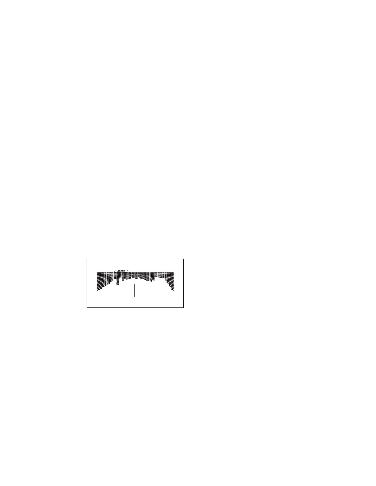
During the
workout,
the profile
on the
speed
tab will
show your
progress.
The flashing segment of the profile represents the
current segment of the workout. The height of the
flashing segment indicates the target speed for the
current segment.
At the end of each segment of the workout, a
series of tones will sound and the next segment of
the profile will begin to flash. If a different resis-
tance level and/or target speed is programmed for
the next segment, the resistance level and/or target
speed will appear in the display for a few seconds
to alert you. The resistance of the pedals will then
change.
As you exercise, you will be prompted to keep
your pedaling speed near the target speed for the
current segment. When an upward-pointing arrow
appears in the display, increase your pace. When a
downward-pointing arrow appears, decrease your
pace. When no arrow appears, maintain your cur-
rent pace.
IMPORTANT: The target speed is intended only
to provide motivation. Your actual pedaling
speed may be slower than the target speed.
Make sure to pedal at a speed that is comfort-
able for you.
If the resistance level for the current segment is
too high or too low, you can manually override
the setting by pressing the Resistance buttons.
IMPORTANT: When the current segment of the
workout ends, the pedals will automatically
adjust to the resistance level programmed for
the next segment.
The workout will continue in this way until the last
segment ends. To stop the workout at any time,
stop pedaling. The time will flash in the display. To
resume the workout, simply resume pedaling.
4. Follow your progress with the display.
See step 4 on page 18.
5. Measure your heart rate if desired.
See step 5 on page 19.
6. When you are finished exercising, the console
will turn off automatically.
See step 6 on page 19.
Profile
  • Page 1 1
  • Page 2 2
  • Page 3 3
  • Page 4 4
  • Page 5 5
  • Page 6 6
  • Page 7 7
  • Page 8 8
  • Page 9 9
  • Page 10 10
  • Page 11 11
  • Page 12 12
  • Page 13 13
  • Page 14 14
  • Page 15 15
  • Page 16 16
  • Page 17 17
  • Page 18 18
  • Page 19 19
  • Page 20 20
  • Page 21 21
  • Page 22 22
  • Page 23 23
  • Page 24 24
  • Page 25 25
  • Page 26 26
  • Page 27 27
  • Page 28 28
  • Page 29 29
  • Page 30 30
  • Page 31 31
  • Page 32 32

NordicTrack 510 EX User manual

Category
Fitness, gymnastics & weight training
Type
User manual

Ask a question and I''ll find the answer in the document

Finding information in a document is now easier with AI