Lincoln Manufacturing 1450 User manual
- Category
- Ovens
- Type
- User manual
This manual is also suitable for

P/N: L371075
REV: 10.21.09
Lincoln Foodservice Products, LLC
1111 North Hadley Road
Fort Wayne, Indiana 46804
Telephone: 260.459.8200
Fax: 888.790.8193
Technical Support: 800.678.9511
lincolnfp.com
PARTS & SERVICE MANUAL
Impinger Advantage Gas w/ Push Button Controls
1450 Series - Domestic
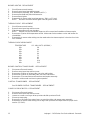
MODELS:
Please note that the model numbering system changed
March 2007.The chart below shows the old model
numbering system and its matching new model number.
Old Model Number
→
New Model Number
1450
→
1450-00z-U-Kxxxx
1451
→
1451-00z-U-Kxxxx

Impinger I – 1450 Series Gas Service Manual - Domestic
2
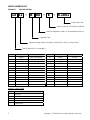
MODEL NUMBER KEY
EXAMPLE: 1451-B00-E-K1801
14 51 - B 00 - E - K1801
CODE LANGUAGE COUNTRY CODE LANGUAGE COUNTRY
0 English Dom. & Int. Default N Finnish Finland
B French France/Luxembourg O Restricted ---
C German Germany P Norwegian Norway
D Italian Italy Q English Japan
E Spanish Spain R Swedish Sweden
F English UK/India/Africa/Hungary S English Australia
G Spanish Mexico/Latin America T Mandarin China
H Portuguese Portugal U Restricted ---
I Not Used --- V English Pacific Rim/Korea
J Danish Denmark W English Middle East
K Dutch & French Belgium X Not Used ---
L Dutch Netherlands Y Not Used ---
M Greek Greece
Z Not Used ---
AGENCY CODE TABLE
CODE AGENCY
N No Agency
E CE & RoHS compliance combined
U US & Canada compliance only
A Advantage style oven to be phased-out
B Australia AGA
Panel Setup Code
Agency Code (i.e. CE & RoHS combined)
Custom Configuration Code (i.e. General Market Version)
Language Code
Indicates change to base assembly (i.e. Natural Gas, 230V, 1 phase, 50 Hz)
Oven Platform Size (i.e. Impinger I)

Impinger I – 1450 Series Gas Service Manual - Domestic
3
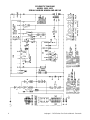
SEQUENCE OF OPERATION
IMPINGER ADVANTAGE
SERIAL NUMBER N28654 AND ABOVE
(OVENS WITH PUSH BUTTON CONTROLS)
MODEL 1450 120VAC 60 HZ. NAT. GAS
MODEL 1451 120VAC 60 HZ. LP GAS
POWER SUPPLY Electrical power is supplied to the oven by a three conductor cordset. Voltage
from the black conductor to the white conductor is 120VAC. The white
conductor is neutral. The green conductor is ground.
CONTROL BOX AUTO
COOL DOWN
When the temperature in the control box reaches 120°F ± 3° (48.9°C ± 1.7°C),
the cooling fan thermostat will switch power to the control box cooling fan. The
thermostat will interrupt power to the cooling fan when the control box
temperature falls to 100°F ± 3° (37.0°C ± 1.7°C).
MAIN FAN CIRCUIT Electrical power is permanently supplied, through a 10 Amp fuse, to the
normally open contacts of the oven power switch. Power is also supplied to the
normally open control box cooling fan thermostat. Closing the oven power
switch supplies 120VAC to the main fan motor and to the control box cooling
fan. Closing the oven power switch also supplies 120VAC to the burner blower
motor, the primary of the oven control transformer and to the centrifugal switch
of the main fan motor.
BURNER CIRCUIT Closing the oven power switch supplies 120VAC to the burner blower motor and
to the normally open centrifugal switch of the main fan motor. As the main fan
motor reaches approx.900 RPM, the centrifugal switch closes supplying
120VAC to the oven control and to the primary of the burner transformer. The
transformer secondary supplies 24VAC, through the centrifugal switch of the
burner blower motor, to the ignition control.
IGNITION CONTROL When the ignition control is supplied with 24VAC, the pilot valve and spark
igniter are energized. Ignition should now occur. After the pilot flame is proven,
the main valve is energized.
TEMPERATURE CONTROL Closing the oven fan switch supplies 120VAC to the primary of the control
transformer and, through the centrifugal switch of the main fan motor, to the
oven control. Secondary voltage, 24VAC, is supplied to the oven control. The
oven control is set to desired temperature. The thermocouple will provide
varying millivolts to the oven control. The oven control supplies 120VAC to the
temperature regulation valve at intermittent intervals to maintain the desired
temperature. The display on the oven control will indicate when the temperature
regulation valve is energized.
NOTE: The display also indicates oven temperature.
CONVEYOR DRIVE Closing the oven power switch supplies 120VAC to the conveyor motor and to
the primary of the control transformer. Secondary voltage, 24VAC, is supplied to
the oven control. Setting the oven control to the desired time outputs voltage,
through a reversing switch, to the conveyor motor.
NOTE: The conveyor system uses a hall effect sensor and magnet to prove
operation of the conveyor motor. If the conveyor motor is not running, “BELT
JAM” is indicated on the display.

Impinger I – 1450 Series Gas Service Manual - Domestic
4
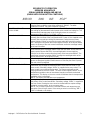
SCHEMATIC DIAGRAM
MODEL 1450, 1451
SERIAL NUMBER N28654 AND ABOVE

Impinger I – 1450 Series Gas Service Manual - Domestic
5
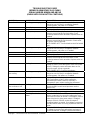
TROUBLESHOOTING GUIDE
IMPINGER ADVANTAGE GAS OVENS
SERIAL NUMBER N28654 AND ABOVE
(OVENS WITH PUSH BUTTON CONTROLS)
SYMPTOM POSSIBLE CAUSE EVALUATION
Oven fan will not run Incoming power supply Check circuit breaker, reset if required. Check power
plug to be sure it is firmly in receptacle. Measure
incoming power, call power co. if needed.
Fuse, 10 Amp Check, replace if necessary.
Fuse holder Check, replace if necessary.
Switch, oven power Check for 120VAC supply to switch. If no voltage is
present, trace wiring back to fuse holder. Check
continuity between switch terminals. Replace switch as
needed.
Motor, main fan Check for 120VAC supply to the motor. If no voltage is
present, trace wiring back to the switch. Check motor
for opens, shorts or grounds.
WITH POWER OFF: Turn fan blade to check for locked
rotor.
No control box cooling Incoming power supply Check circuit breaker, reset if required. Check power
plug to be sure it is firmly in receptacle. Measure
incoming power, call power co. if needed.
Fuse, 10 Amp Check, replace if necessary.
Fuse holder Check, replace if necessary.
Switch, oven power Check for 120VAC supply to switch. If no voltage is
present, trace wiring back to fuse holder. Check
continuity between switch terminals. Replace switch as
needed.
Cooling fan Check for 120VAC supply to the cooling fan. If no
voltage is present, trace wiring back to the oven power
switch. If voltage is present and motor does not run,
check for opens, shorts or grounds.
WITH POWER OFF: Check for locked rotor.
No automatic control
box cooling
Incoming power supply Check circuit breaker, reset if required. Check power
plug to be sure it is firmly in receptacle. Measure
incoming power. Call power co. if needed.
Cooling fan thermostat Check cooling fan thermostat (thermostat closes at
120°F and opens at 100°F). With cooling fan
thermostat pre-heated, check for continuity. If
thermostat is open, replace cooling fan thermostat.
Control box cooling
fan continues to run
Cooling fan thermostat See “Cooling fan thermostat” (NOTE: Thermostat will
remain closed if control box temperature remains
above 120°F.
Oven will not heat Main fan If not operating, refer to “Oven fan will not run”.
Gas supply Check for adequate gas supply to oven.
Centrifugal switch of main fan
motor
Check for 120VAC at wire #5 (input to centrifugal
switch, located at 6-pin connector inside motor cover
near main fan motor) to neutral. If no voltage is present,
trace wiring back to oven power switch. If voltage is
present, check for 120VAC at wire #9 (output of
centrifugal switch) to neutral. If no voltage is present at
wire #9, and the motor is running, replace the main fan
motor.
Burner blower motor Check for 120VAC supplied to burner blower motor. If
no voltage is present, trace wiring back to primary of
control transformer. If voltage is present and motor is

Impinger I – 1450 Series Gas Service Manual - Domestic
6
not running, check for opens, shorts or grounds.
WITH POWER OFF: Turn motor to check for locked
rotor. Replace burner blower motor as needed.
Burner transformer Check for 120VAC supplied to primary of burner
transformer. If no voltage is present, trace wiring back
to centrifugal switch of main fan motor. If voltage is
present, check for 24VAC supply at transformer
secondary. If there is primary voltage but no secondary
voltage, replace burner transformer.
Centrifugal switch of burner
blower motor
Check for 24VAC at motor connector, wire #19 (input to
centrifugal switch) to neutral. If no voltage is present,
trace wiring back to burner transformer. If voltage is
present, check for 24VAC at wire #20 (output of
centrifugal switch) to neutral. If no voltage is present at
wire #20 and motor is running, replace burner blower
motor.
Ignition control Check for 24VAC supply to the ignition control. If no
voltage is present, trace wiring back to centrifugal
switch of burner blower motor. If voltage is present,
check for 24VAC at pin #3 and ground (pilot valve).
NOTE: The Honeywell ignition control has a 30 second
pre-purge (time delay) built in. If voltage is not present,
replace ignition control. If the pilot valve is energized,
check to see that the high voltage igniter circuit is also
energized. To check, disconnect the igniter lead from
the ignition control.
No pilot flame If the ignition control is supplied with 24Vac and the
pilot valve (internal to valve assembly) and igniter
circuits are energized, visually check for pilot flame.
This may be done by opening the small inspection door
on the end of the burner, or by opening the main oven
door and looking under the lower finger housings on
the right side of the oven. If no pilot flame is visible,
check the pilot shut-off valve.
Pilot shut-off valve Check to see that the pilot shut-off valve is open (shut-
off valve is located between valve assembly and
burner).
Pilot tube Check for gas pressure at the pilot tube. Disconnect
pilot tube at burner and connect a manometer to pilot
tube. If no gas pressure is present during ignition,
check for blockage in pilot tube or pilot shut-off valve. If
these are clear, and there is gas supplied to the oven,
replace the gas valve.
Pilot orifice If there is gas pressure at the pilot tube, check the pilot
orifice for obstructions. Replace as needed.
Burner igniter Check the burner igniter head for any obstructions, also
check for frayed or broken wire. Check spark gap (gap
should be .100 to .125 inch). If there is visible damage,
replace burner igniter.
NOTE: Flame should be on
at this time
Pilot flame, but no
main flame
Control transformer Check for 120VAC supply to the primary of the control
transformer. If no voltage is present, trace wiring back
to the oven power switch. If voltage is present, check
foe 24VAC at the transformer secondary. If there is
primary voltage, but no secondary voltage, replace
control transformer.
Oven control Check for 24VAC supply to oven control. If no voltage
is present, trace wiring back to control transformer. If
24VAC is present, check for a read-out on the display.
If there is 24VAC supplied, but there is no read-out on

Impinger I – 1450 Series Gas Service Manual - Domestic
7
the display, replace oven control. If there is a read-out
on the control, set the control to maximum temperature
(see Installation operations manual for temperature
adjustment). With the control set at maximum
temperature, check for 120VAC at the temperature
regulation valve. If there is voltage at the temperature
regulation valve, proceed to “Temperature regulation
valve” for next check. If there is no voltage at the
temperature regulation valve, trace wiring back to the
oven control. If there is no voltage output at the oven
control, check the read-out on the oven control. If the
control reads “PROBE FAIL”, this indicates that the
thermocouple has failed or become disconnected from
the oven control.
Thermocouple Check to be sure that the thermocouple is securely
connected to the oven control. If the thermocouple is
connected to the oven control, and the control indicates
“PROBE FAIL”, disconnect the thermocouple from the
oven control and measure the resistance of the
thermocouple. The thermocouple should read approx.
11Ω. If these readings are not achieved, replace the
thermocouple. If these readings are correct, proceed.
Oven control If the thermocouple checks good, but the oven control
display indicates that there is a thermocouple failure,
replace the oven control. If the oven control indicates a
temperature reading, but the oven will not heat,
proceed.
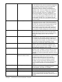
Thermocouple WITH POWER ON AND THERMOCOUPLE
ATTACHED TO THE OVEN CONTROL: Measure the
DC millivolt output of the thermocouple. Refer to the
thermocouple chart (located in the “Removal” section of
the manual) for proper millivolt readings. If these
readings are not achieved, replace thermocouple.
Oven control If the thermocouple checks good, but there is no
120VAC output to the temperature regulation valve,
replace the oven control. If there is 120VAC output to
the temperature regulation valve, proceed.
Temperature regulation valve Check for 120VAC supplied to the temperature
regulation valve. If voltage is present, listen for valve to
open and close. Also check for opens or shorts in the
operating coil. Replace temperature regulation valve as
needed.
Intermittent heating Thermal/overload of main fan
and burner blower motors
The main fan motor and burner blower motor are
equipped with internal thermal protection and will cease
to operate if overheating occurs. As the motors
overheat and then cool, this will cause the heating
system to cycle on and off intermittently. Improper
ventilation or lack of preventive maintenance may
cause this problem. Also, most of the problems listed
under “Oven will not heat” can cause intermittent
failure.
Conveyor will not run Incoming power supply Check circuit breaker, reset if required. Check power
plug to be sure it is firmly in receptacle. Measure
incoming power, call power co. if needed.
Fuse, 10 Amp Check, replace if necessary.
Fuse holder Check, replace if necessary.
Switch, oven power Check for 120VAC supply to switch. If no voltage is
present, trace wiring back to fuse holder. Check
continuity between switch terminals. Replace switch as
needed.

Impinger I – 1450 Series Gas Service Manual - Domestic
8
Control transformer Check for 120VAC supply to the primary of the control
transformer. If no voltage is present, trace wiring back
to the oven power switch. If voltage is present, check
foe 24VAC at the transformer secondary. If there is
primary voltage, but no secondary voltage, replace
control transformer.
Conveyor motor Check for 120VAC supply to conveyor motor at wire #6
to neutral. If no voltage is present, trace wiring back to
oven power switch. If voltage is present and motor will
not run, check the motor windings for opens or shorts.
WITH POWER OFF: Check the motor windings as
follows:
Grey to black - 38Ω approx.
Grey to blue - 38Ω approx.
Blue to black - 75Ω approx.
If any of the above fails, replace conveyor motor.
Capacitor, conveyor motor Check for shorts or grounds. Replace capacitor as
needed.
WARNING: Capacitor has a stored charge, discharge
before testing.
Switch, conveyor reversing Check continuity between switch terminals. Replace as
needed.
Oven control If there is 120VAC supplied to the motor, and the
motor, capacitor, and reversing switch check good,
replace the oven control.
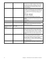
Conveyor motor runs,
but there is no speed
display
NOTE: Display will indicate
“BELT JAM”
Oven control Check for output voltage from oven control to hall effect
sensor (sensor is located in conveyor motor). Measure
voltage at the motor connector, red wire and yellow
wire. Voltage should be approx. 10VDC. If no voltage is
present, trace wiring back to oven control. If there is no
voltage present at the oven control, replace the oven
control.
Conveyor motor If there is voltage supplied to the hall effect sensor,
check for a frequency output from the hall effect
sensor. Measure frequency across the yellow and white
wires at the motor connector. Frequency reading
should be approx. 25 – 100 Hz. If these readings are
not achieved, replace conveyor motor. If these readings
are achieved, proceed.
Oven control If the hall effect sensor readings are correct, but there
is no speed indicated on the display, replace the oven
control.

Impinger I – 1450 Series Gas Service Manual - Domestic
9
REMOVAL, INSTALLATION & ADJUSTMENTS
IMPINGER ADVANTAGE SERIES
CAUTION!
BEFORE REMOVING OR INSTALLING ANY COMPONENT IN THE IMPINGER
OVEN BE SURE TO DISCONNECT ELECTRICAL POWER AND GAS SUPPLY
MOTOR, MAIN FAN - REPLACEMENT
1. Shut off power at main breaker.
2. Remove louvered motor cover from back of oven.
3. Remove wireway by taking out the (5) five hex screws.
4. Disconnect wiring from motor.
5. Remove the twelve (12) hex head bolts from the oven back and slide back straight out of the oven.
6. Remove two (2) bolts from fan hub and remove fan from motor shaft.
NOTE: Measure distance from fan blade to rear wall assembly before removal to aid in reassembly.
7. Remove the eight (8) hex head bolts from the motor mount and slide the motor assembly out of the oven
back.
8. Remove motor by taking off motor clamp and removing the four (4) mounting nuts and washers.
9. Reassemble in reverse order. When motor mount assembly is set on the oven back, align motor shaft in
the center of the hole. Set fan assembly on the motor shaft.
NOTE: A. Torque specs on bolts (150 in/lb. torque)
B. It is recommended that an anti-seize compound be brushed on to the bolts around the back
and motor mount bracket before assembly.
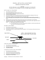
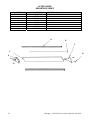
FAN, MAIN - REPLACEMENT
1. Shut off power at main breaker.
2. Remove back assembly. (See MOTOR, MAIN FAN)
3. Reinstall and locate fan so that the bottom of the fan spider is 1 1/2" from the top of the oven back cone.
(See Drawing)
FAN HUB
CONE
FAN SPIDER
1 1/2 INCH
NOTE: MEASUREMENT MUST BE
MADE FROM CONE TO FAN SPIDER
CAPACITOR, MOTOR - REPLACEMENT
1. Shut off power at main breaker.
2. Remove motor cover from back of oven.
3. Discharge capacitor.
4. Remove and replace.
COOLING FAN, CONTROL BOX - REPLACEMENT
1. Shut off power at main breaker.
2. Remove control panel top and front cover.
3. Remove four (4) screws from the fan frame.
4. Disconnect cord and plug and remove fan.
5. Reassemble in reverse order.

Impinger I – 1450 Series Gas Service Manual - Domestic
10
THERMOSTAT, COOLING FAN - REPLACEMENT
1. Shut off power at main breaker.
2. Remove control panel top and front cover.
3. Remove lead wires and mark for reassembly.
4. Remove two (2) screws and remove thermostat.
5. Reassemble in reverse order.
BURNER BLOWER MOTOR - REPLACEMENT
1. Shut off power at main breaker.
2. Remove control panel top and front cover.
3. Unplug motor connector.
4. Remove three (3) screws from blower tube at burner housing.
5. Remove air shutter assembly from old motor for installation on new motor assembly.
6. Reassemble in reverse order and check system operation.
NOTE: Check air shutter adjustment and adjust if necessary. Set air shutter at approx. 1/4" and adjust
to get a blue flame with an occasional tip of yellow under high flame. A view port in the burner assembly
should be used to observe flame.
BLOWER WHEEL, BURNER
This is part of the burner blower motor assembly.
TO REMOVE THE BLOWER WHEEL FOR PERIODIC CLEANING:
1. Shut off power at main breaker.
2. Remove control panel top and front cover.
3. Remove air shutter held by 3 screws.
4. Loosen set screws on blower wheel hub and pull straight out.
5. Reassemble in reverse order.
NOTE: There is no critical placement of the blower wheel on the motor shaft. Just back as far as
it will go and then spin the blower to be sure it is not rubbing.
BURNER CONTROL - REPLACEMENT
1. Shut off power at main breaker.
2. Remove control panel top and front cover.
3. Remove wires from control, note wire numbers and location for reassembly.
4. Remove Two (2) screws from control and replace.
5. Reassemble in reverse order and check system operation.
BURNER ASSEMBLY
1. Shut off power at main breaker.
2. Shut off gas supply.
3. Remove control panel top and front panel.
4. Remove gas control valve (See "GAS CONTROL VALVE")
5. Disconnect pilot tube.
6. Remove solenoid valve. (See "TEMPERATURE REGULATION VALVE")
7. Remove four (4) screws that secure the burner backing plate.
8. Remove burner assembly from housing, the main and pilot orifice, flame target, pilot shield (main and
extension), burner ignitor can now be changed or serviced as needed.
9. Reassemble in reverse order. Check all gas line fittings for leaks.
GAS CONTROL VALVE - REPLACEMENT
1. Shut off power at main breaker.
2. Shut off gas supply.
3. Remove control panel top and front cover.
4. Disconnect the gas piping from the back of the unit.
5. Remove the four(4) screws from the incoming nipple mounting bracket.

Impinger I – 1450 Series Gas Service Manual - Domestic
11
6. Remove incoming nipple.
7. Remove pilot tube assembly from control valve.
8. Disconnect pipe union just above solenoid valve.
9. Disconnect wiring from control valve making note of wire numbers and location. Remove piping from old
valve for installation on new valve.
10. Reassemble in reverse order - after assembly is complete, be sure to check manifold pressure
(3.5" W.C. NAT GAS 10" W.C. LP) and adjust if necessary. (See Section "MANIFOLD PRESSURE -
ADJUSTMENT")
NOTE: Check all gas line fittings for leaks after installation.
FRONT VIEW
MANIFOLD ADJUSTMENT
SCREW LOCATED UNDER
COVER SCREW
TOP VIEW
PILOT
LINE
CONNECTION
MANIFOLD PRESSURE
ADJUSTMENT CONNECTION
MANIFOLD ADJUSTMENT
SCREW LOCATED UNDE
R
COVER SCREW
MANIFOLD PRESSURE - ADJUSTMENT
1. Remove control panel top and front cover.
2. WITH ELECTRIC POWER AND GAS OFF: Remove the outlet pressure tap plug from the gas control
valve and install the adapter fitting and manometer.
3. Turn on electric power and gas and start-up oven.
4. With oven at full fire, manifold pressure should be (3.5" W.C. NAT/ 10" W.C. LP). If adjustment is
needed, remove cover screw from valve body and adjust by turning regulator screw. (C.W. to increase,
C.C.W. to decrease).
5. Turn off electric power and gas, replace cover screw, remove manometer and adapter; Replace
pressure tap plug.
6. Check pressure tap for gas leaks before closing panel.
7. Close control panel and check system operation.
TEMPERATURE REGULATION VALVE - REPLACEMENT
1. Shut off power at main breaker.
2. Shut off gas supply.
3. Remove control panel top and front cover.
4. Remove gas control valve (See "GAS CONTROL VALVE")
5. Disconnect wires from temperature regulation valve.
6. Remove two (2) hex nuts that hold main orifice bracket in place.
7. Remove temperature regulation valve assembly.
8. Remove piping from temperature regulation valve.
9. Reassemble in reverse order.
10. Check all fittings for leaks.

Impinger I – 1450 Series Gas Service Manual - Domestic
12
BURNER IGNITOR - REPLACEMENT
1. Shut off power at main breaker.
2. Remove control panel top and front cover.
3. Remove burner assembly. (SEE "BURNER ASSY.")
4. Remove pilot shield and pilot shield extension.
5. Remove burner ignitor.
6. Reassemble in reverse order (spark gap approx. .100 in. or 2.5 mm)
NOTE: Be sure to reconnect burner ignitor cable to ignition control.
THERMOCOUPLE - REPLACEMENT
1. Shut off power at main breaker.
2. Remove control panel top and front cover.
3. Slide thermocouple out of oven chamber.
NOTE: Remove conveyor and bottom fingers to aid in removal and installation of thermocouple.
4. Remove two (2) wires from temperature control. Make note of wire numbers or color and location for
reinstallation.
5. Reassemble in reverse order making sure the metal end on the thermocouple is in the wire form in the
oven chamber.
THERMOCOUPLE MEASURMENT
TEMPERATURE D.C. MILLVOLTS (APPROX.)
200° 2.8
250° 4.0
300° 5.1
350° 6.0
400° 7.1
450° 8.2
500° 9.3
550° 10.4
600° 11.5
BURNER CONTROL TRANSFORMER - REPLACEMENT
1. Shut power off at main breaker.
2. Remove control panel top and front cover.
3. Remove two (2) wires on primary side, note color and location.
4. Remove two (2) wires on secondary side, note color and location.
5. Remove two (2) screws from transformer base and replace assembly.
6. Reinstall in reverse order and check system operation.
CONTROL TRANSFORMER – REPLACEMENT
See “BURNER CONTROL TRANSFORMER – REPLACEMENT”
CONVEYOR DRIVE MOTOR - REPLACEMENT
1. Shut power off at main breaker.
2. Remove control panel top and front cover.
3. Loosen set screw on conveyor drive sprocket and slide sprocket off shaft.
4. Disconnect motor plug.
5. Remove four (4) screws from motor frame, on control box side, and remove motor assembly.
6. Reassemble in reverse order making sure to align chain sprockets and adjust motor for proper chain
tension (1/2" SAG).

Impinger I – 1450 Series Gas Service Manual - Domestic
13
REVERSING CONVEYOR DIRECTION
All ovens leaving our plant are wired to operate conveyors from left to right. To reverse conveyor direction, use
the following procedure.
1. Shut off power at oven switch.
2. Set conveyor reversing switch in the other position.
3. Turn oven “on” and check for proper operation.
MAIN ORIFICE - REPLACEMENT
1. Shut off power at main breaker.
2. Remove control panel top and front panel.
3. Remove gas control valve assy.
4. Remove two (2) nuts from burner orifice bracket.
5. Disconnect pipe union.
6. Remove assembly and replace main orifice.
7. Reassemble in reverse order and check system operation. NOTE: Check all gas line fittings for leaks.
PILOT ORIFICE - REPLACEMENT
1. Shut off power at main breaker.
2. Shut off gas supply.
3. Remove burner assembly (See "Burner Assembly").
4. Remove pilot line from pilot orifice.
5. Remove pilot orifice from burner ignitor.
6. Reassemble in reverse order. NOTE: Check all gas line fittings for leaks.
ON-OFF SWITCH - REPLACEMENT
1. Shut off power at main breaker.
2. Remove control box cover.
3. Remove access cover.
4. Depress spring clips on side of switch and push out.
5. Remove wires from back of switch, note wire number and location.
6. Reassemble in reverse order and check system operation.
NOTE: Make sure switch housing is fully seated in control box housing.
OVEN CONTROL – REPLACEMENT
A. Shut off power at main breaker.
B. Remove control box cover and front panel.
C. Remove all wiring connections and mark for reassembly.
D. Remove oven control by pulling control from the mounting pins. Remove control from oven.
E. Before installing new oven control, set voltage jumper (located at the bottom center of the oven
control) to the proper voltage (120V/240V) position. Install the four pushbutton extensions
(included with the oven control) by pushing the extensions onto the four set buttons on control.
F. Reassemble in reverse order and check system operation.
G. Set the oven control for the proper operating mode. The 1400 series ovens use a single temperature
control system. The oven control must be set to the proper operating mode. Set the control as follows:
With the oven power switch “off”, depress the “time” and “up” buttons and turn the oven “on”. Control
will indicate “Imp I or Imp II” Release the buttons, The control will indicate “Temp to store”. Press the
“up” or “down” button until “Imp I” appears on the display. Press the “temp” button. The control is now
set for single burner operation.
FUSE HOLDER – REPLACEMENT
1. Shut off power at main breaker.
2. Remove control box cover.
3. Remove all wiring from fuse holder and mark for reassembly.
4. Remove mounting nut for fuse holder and remove fuse holder.
5. Reassemble in reverse order and check system operation.

Impinger I – 1450 Series Gas Service Manual - Domestic
14
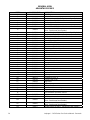
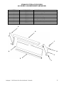
GENERAL VIEW
ADVANTAGE SERIES
LETTER PART NUMBER DESCRIPTION
A 369003 Door hinge
B
See Access Door Section
Access window assembly
C 369337 Retainer (old style) (NLA – See Access Door Section)
369929 Retainer (new style) (NLA – See Access Door Section)
D 369828 Handle spacer
E 369209 Latch & strike
F 369310 Screw, 6-32 x 3/16” (NLA – See Access Door Section)
G 369308
Bottom, access window
(NLA – See Access Door Section)
H 369334 Access door glass (NLA – See Access Door Section)
J 369309 Top, access window (NLA – See Access Door Section)
K 350638 Handle (NLA – See Access Door Section)
L 369311 Handle spacer (2 req.)
M 369336 Door latch
N 369906 Screw, 8-32 x 5/8”
O 370110 Door assembly (solid)
P 369157 Door assembly (with window)
Q 1534 Finger support assembly
R 369057 Support bracket pin
S 369643 Strike assembly
T 1009 Oven top
U 369062 Top, control box
V 369140 Compression spring
W 369903 Washer, flat
X 369141 Conveyor hold down bracket
Y 369139 Shoulder screw
Z 369058 Baffle, inlet and outlet
* 369211 Thumb screw (not shown)
AA 369203 Stud, wing head
BB 369749 Chain cover kit (includes AA, CC)
CC 369204 Split ring retainer
DD 369373 Receptacle, snap –in
EE 369748 Bracket, chain cover
FF 369328 Leg, stand
GG 369052 Adjustable leg
HH 369030 Caster, 6”
JJ 369904 Insulation holder assembly
KK 369053 Finger housing
LL
Columnating plates –
see installation operations manual
MM 369055 Finger cover
NN 369218 Crumb pan, internal
OO 369926
Window frame, bottom
(NLA – See Access Door Section)
PP 369925
Glass, access window
(NLA – See Access Door Section)
QQ 369927 Window frame, top (NLA – See Access Door Section)

Impinger I – 1450 Series Gas Service Manual - Domestic
15

Impinger I – 1450 Series Gas Service Manual - Domestic
16
ACCESS DOOR
ADVANTAGE SERIES
LETTER PART NUMBER DESCRIPTION
369110 Access Door Assembly
A 370724 Extrusion
B 369928 Dowel, Access Door
C 370726 Bracket Assembly
D 370725 Dowel Thread
E 370727 Bracket Assembly
F 370723 Glass
Not Shown 369929 Retainer, Window
A
B
C
D
E
F

Impinger I – 1450 Series Gas Service Manual - Domestic
17
STAINLESS STEEL ACCESS DOOR
ALL MODELS (SN 0908210000875 AND ABOVE)
LETTER PART NUMBER DESCRIPTION
369110 Access Door Assembly
A 371140 Bracket Assembly, Left
B 371142 Dowel, Access Door
C 370722 Screw
D 371143 8-32 x 3/8 Hx Serr Flng
E 371141 Bracket Assembly, Right
F 370725 Dowel Thread
G 371144 Access Door Frame (top or bottom)
H 370723 Glass
A
B
C
D
E
F
G
H

Impinger I – 1450 Series Gas Service Manual - Domestic
18
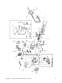
CONTROL BOX – 1450, 1451
S/N N28654 and ABOVE
LETTER PART # DESCRIPTION
A 369263 Gas Valve
B 369344 Pilot Shut Off Valve
C 369398 Solenoid Valve Nat/LP
D 370059 Manifold, Burner
E 369072 Main Orifice, Nat.
369099 Main Orifice, L.P.
F 369144 Pilot Shield Extension
G 369202 Pilot Shield, Main
H 369076 Burner Igniter
I 369075 Flame Sensor
J 369142 Flame Target
K 369366 Burner Blower Motor
L 369399 Air Shutter
M 369400 Plate, Air Shutter
N 370362 Thermocouple, Type K
O 370368 Conveyor Motor
P 369158 Sprocket, Drive
Q 369124 Cooling Fan
R 369393 Ignition Control
S 370359 Reversing Switch
T 369507 Control Box Thermostat
U 369331 Finger Guard, Cooling Fan
V 369531 Transformer, 24 VAC
W 370352 Capacitor, Conveyor motor
Y 370418 Top, Control Box
Z 370355 Control, Oven
AA 370354 Facia, Front
BB 369805 Switch, On-Off
CC 370363 Front Cover
DD 369537 Power Cord
EE 369129 Fuse Holder
FF 369166 Fuse, 10 A
GG 353014 Ground Lug

Impinger I – 1450 Series Gas Service Manual - Domestic
19

Impinger I – 1450 Series Gas Service Manual - Domestic
20
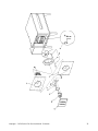
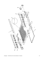
OVEN BACK
ADVANTAGE SERIES
GAS AND ELECTRIC
LETTER PART NUMBER DESCRIPTION
A 369808 Cover, motor (gas ovens)
370140 Cover, motor (electric ovens)
B 369800 Motor, main fan (60 Hz.)
369214 Motor, main fan (50 Hz.)
C 369033 Motor clamp
D 369215 Motor support assembly
E 369192 Capacitor, 7.5 MFD
F 369306 Oven back assembly, gas oven
G 369646 Stand-off
H 369647 Inlet panel
J 369213 Main fan
K 369547 Bracket, thermostat
M 369287 Heating element, 208V
369315 Heating element, 220V
369122 Heating element, 240V
Page is loading ...
Page is loading ...
Page is loading ...
Page is loading ...
-
 1
1
-
 2
2
-
 3
3
-
 4
4
-
 5
5
-
 6
6
-
 7
7
-
 8
8
-
 9
9
-
 10
10
-
 11
11
-
 12
12
-
 13
13
-
 14
14
-
 15
15
-
 16
16
-
 17
17
-
 18
18
-
 19
19
-
 20
20
-
 21
21
-
 22
22
-
 23
23
-
 24
24


Lincoln Manufacturing 1450 User manual
- Category
- Ovens
- Type
- User manual
- This manual is also suitable for
Ask a question and I''ll find the answer in the document
Finding information in a document is now easier with AI
Related papers
-
 Lincoln Manufacturing 1133-000-A User manual
-
 Lincoln Manufacturing 3240-2 User manual
-
Lincoln Manufacturing 1400 Serial 28654 & above Domestic (Electric) User manual
-
-
Lincoln Manufacturing 1454 User manual
-
-
 Lincoln Manufacturing Series 1200 User manual
-
 Lincoln Manufacturing 1200 User manual
-
 Lincoln Manufacturing Impinger 1457 User manual
-
 Lincoln Manufacturing 1133-000-A User manual


Other documents
-
Cub Cadet 1451 User manual
-
Lincoln Convection Oven 1451 User manual
-
-
-
Broan GB5BW Product information
-
-
-
-
-