
GRUNDFOS INSTRUCTIONS
DME, Variant AR (60-940 l/h)
Installation and operating instructions


Table of contents
3
DME, Variant AR (60-940 l/h)
Declaration of conformity . . . . . . . . . . . . . . . . . . . . . . . . . . . . . . . . . . . . . . . . . . 4
English (GB)
Installation and operating instructions. . . . . . . . . . . . . . . . . . . . . . . . . . . . . . . . . 5
Dansk (DK)
Monterings- og driftsinstruktion. . . . . . . . . . . . . . . . . . . . . . . . . . . . . . . . . . . . . 34
Deutsch (DE)
Montage- und Betriebsanleitung . . . . . . . . . . . . . . . . . . . . . . . . . . . . . . . . . . . . 63
Ελληνικά (GR)
Οδηγίες εγκατάστασης και λειτουργίας . . . . . . . . . . . . . . . . . . . . . . . . . . . . . . . 92
Español (ES)
Instrucciones de instalación y funcionamiento . . . . . . . . . . . . . . . . . . . . . . . . 122
Français (FR)
Notice d'installation et de fonctionnement. . . . . . . . . . . . . . . . . . . . . . . . . . . . 151
Italiano (IT)
Istruzioni di installazione e funzionamento . . . . . . . . . . . . . . . . . . . . . . . . . . . 180
Nederlands (NL)
Installatie- en bedieningsinstructies . . . . . . . . . . . . . . . . . . . . . . . . . . . . . . . . 209
Português (PT)
Instruções de instalação e funcionamento . . . . . . . . . . . . . . . . . . . . . . . . . . . 238
Suomi (FI)
Asennus- ja käyttöohjeet. . . . . . . . . . . . . . . . . . . . . . . . . . . . . . . . . . . . . . . . . 267
Svenska (SE)
Monterings- och driftsinstruktion . . . . . . . . . . . . . . . . . . . . . . . . . . . . . . . . . . . 296
Appendix 1 . . . . . . . . . . . . . . . . . . . . . . . . . . . . . . . . . . . . . . . . . . . . . . . . . . . 325
Appendix 2 . . . . . . . . . . . . . . . . . . . . . . . . . . . . . . . . . . . . . . . . . . . . . . . . . . . 326

Declaration of conformity
4
Declaration of conformity
GB Declaration of Conformity
We, Grundfos, declare under our sole responsibility that the products
DME, to which this declaration relates, are in conformity with these
Council directives on the approximation of the laws of the EC member
states:
– Machinery Directive (2006/42/EC).
Standards used: EN 809: 1998, EN ISO 12100-1+A1: 2009,
EN ISO 12100-2+A1: 2009
– Low Voltage Directive (2006/95/EC).
Standard used: EN 60204-1+A1: 2009.
– EMC Directive (2004/108/EC).
Standards used: EN 61000-6-2: 2005, EN 61000-6-4: 2007.
DK Overensstemmelseserklæring
Vi, Grundfos, erklærer under ansvar at produkterne DME som denne
erklæring omhandler, er i overensstemmelse med disse af Rådets
direktiver om indbyrdes tilnærmelse til EF-medlemsstaternes
lovgivning:
– Maskindirektivet (2006/42/EF).
Anvendt standarder: EN 809: 1998, EN ISO 12100-1+A1: 2009,
EN ISO 12100-2+A1: 2009.
– Lavspændingsdirektivet (2006/95/EF).
Anvendt standard: EN 60204-1+A1: 2009.
– EMC-direktivet (2004/108/EF).
Anvendte standarder: EN 61000-6-2: 2005, EN 61000-6-4: 2007.
DE Konformitätserklärung
Wir, Grundfos, erklären in alleiniger Verantwortung, dass die Produkte
DME, auf die sich diese Erklärung bezieht, mit den folgenden Richtlinien
des Rates zur Angleichung der Rechtsvorschriften der EU-
Mitgliedsstaaten übereinstimmen:
– Maschinenrichtlinie (2006/42/EG).
Normen, die verwendet wurden: EN 809: 1998, EN ISO 12100-1+A1:
2009, EN ISO 12100-2+A1: 2009.
– Niederspannungsrichtlinie (2006/95/EG).
Norm, die verwendet wurde: EN 60204-1+A1: 2009.
– EMV-Richtlinie (2004/108/EG).
Normen, die verwendet wurden: EN 61000-6-2: 2005,
EN 61000-6-4: 2007.
GR ∆ήλωση Συμμόρφωσης
Εμείς, η Grundfos, δηλώνουμε με αποκλειστικά δική μας ευθύνη ότι τα
προϊόντα DME στα οποία αναφέρεται η παρούσα δήλωση,
συμμορφώνονται με τις εξής Οδηγίες του Συμβουλίου περί προσέγγισης
των νομοθεσιών των κρατών μελών της ΕΕ:
– Οδηγία για μηχανήματα (2006/42/EC).
Πρότυπα που χρησιμοποιήθηκαν: EN 809: 1998,
EN ISO 12100-1+A1: 2009, EN ISO 12100-2+A1: 2009.
– Οδηγία χαμηλής τάσης (2006/95/EC).
Πρότυπο που χρησιμοποιήθηκε: EN 60204-1+A1: 2009.
– Οδηγία Ηλεκτρομαγνητικής Συμβατότητας (EMC) (2004/108/EC).
Πρότυπα
που χρησιμοποιήθηκαν: EN 61000-6-2: 2005,
EN 61000-6-4: 2007.
ES Declaración de Conformidad
Nosotros, Grundfos, declaramos bajo nuestra entera responsabilidad
que los productos DME, a los cuales se refiere esta declaración, están
conformes con las Directivas del Consejo en la aproximación de las
leyes de las Estados Miembros del EM:
– Directiva de Maquinaria (2006/42/CE).
Normas aplicadas: EN 809: 1998, EN ISO 12100-1+A1: 2009,
EN ISO 12100-2+A1: 2009.
– Directiva de Baja Tensión (2006/95/CE).
Norma aplicada: EN 60204-1+A1: 2009.
– Directiva EMC (2004/108/CE).
Normas aplicadas: EN 61000-6-2: 2005, EN 61000-6-4: 2007.
FR Déclaration de Conformité
Nous, Grundfos, déclarons sous notre seule responsabilité, que les
produits DME, auxquels se réfère cette déclaration, sont conformes aux
Directives du Conseil concernant le rapprochement des législations des
Etats membres CE relatives aux normes énoncées ci-dessous :
– Directive Machines (2006/42/CE).
Normes utilisées : EN 809 : 1998, EN ISO 12100-1+A1 : 2009,
EN ISO 12100-2+A1 : 2009.
– Directive Basse Tension (2006/95/CE).
Norme utilisée : EN 60204-1+A1: 2009.
– Directive Compatibilité Electromagnétique CEM (2004/108/CE).
Normes utilisées : EN 61000-6-2: 2005, EN 61000-6-4: 2007.
IT Dichiarazione di Conformità
Grundfos dichiara sotto la sua esclusiva responsabilità che i prodotti
DME, ai quali si riferisce questa dichiarazione, sono conformi alle
seguenti direttive del Consiglio riguardanti il riavvicinamento delle
legislazioni degli Stati membri CE:
– Direttiva Macchine (2006/42/CE).
Norme applicate: EN 809: 1998, EN ISO 12100-1+A1: 2009,
EN ISO 12100-2+A1: 2009.
– Direttiva Bassa Tensione (2006/95/CE).
Norma applicata: EN 60204-1+A1: 2009.
– Direttiva EMC (2004/108/CE).
Norme applicate: EN 61000-6-2: 2005, EN 61000-6-4: 2007.
NL Overeenkomstigheidsverklaring
Wij, Grundfos, verklaren geheel onder eigen verantwoordelijkheid dat
de producten DME waarop deze verklaring betrekking heeft, in
overeenstemming zijn met de Richtlijnen van de Raad in zake de
onderlinge aanpassing van de wetgeving van de EG Lidstaten
betreffende:
– Machine Richtlijn (2006/42/EC).
Gebruikte normen: EN 809: 1998, EN ISO 12100-1+A1: 2009,
EN ISO 12100-2+A1: 2009.
– Laagspannings Richtlijn (2006/95/EC).
Gebruikte norm: EN 60204-1+A1: 2009.
– EMC Richtlijn (2004/108/EC).
Gebruikte normen: EN 61000-6-2: 2005, EN 61000-6-4: 2007.
PT Declaração de Conformidade
A Grundfos declara sob sua única responsabilidade que os produtos
DME, aos quais diz respeito esta declaração, estão em conformidade
com as seguintes Directivas do Conselho sobre a aproximação das
legislações dos Estados Membros da CE:
– Directiva Máquinas (2006/42/CE).
Normas utilizadas: EN 809: 1998, EN ISO 12100-1+A1: 2009,
EN ISO 12100-2+A1: 2009.
– Directiva Baixa Tensão (2006/95/CE).
Norma utilizada: EN 60204-1+A1: 2009.
– Directiva EMC (compatibilidade electromagnética) (2004/108/CE).
Normas utilizadas: EN 61000-6-2: 2005, EN 61000-6-4: 2007.
FI Vaatimustenmukaisuusvakuutus
Me, Grundfos, vakuutamme omalla vastuullamme, että tuotteet DME,
joita tämä vakuutus koskee, ovat EY:n jäsenvaltioiden lainsäädännön
yhdenmukaistamiseen tähtäävien Euroopan neuvoston direktiivien
vaatimusten mukaisia seuraavasti:
– Konedirektiivi (2006/42/EY).
Sovellettavat standardit: EN 809: 1998, EN ISO 12100-1+A1: 2009,
EN ISO 12100-2+A1: 2009.
– Pienjännitedirektiivi (2006/95/EY).
Sovellettu standardi: EN 60204-1+A1: 2009.
– EMC-direktiivi (2004/108/EY).
Sovellettavat standardit: EN 61000-6-2: 2005, EN 61000-6-4: 2007.
SE Försäkran om överensstämmelse
Vi, Grundfos, försäkrar under ansvar att produkterna DME, som
omfattas av denna försäkran, är i överensstämmelse med rådets direktiv
om inbördes närmande till EU-medlemsstaternas lagstiftning,
avseende:
– Maskindirektivet (2006/42/EG).
Tillämpade standarder: EN 809: 1998, EN ISO 12100-1+A1: 2009,
EN ISO 12100-2+A1: 2009.
– Lågspänningsdirektivet (2006/95/EG).
Tillämpad standard: EN 60204-1+A1: 2009.
– EMC-direktivet (2004/108/EG).
Tillämpade standarder: EN 61000-6-2: 2005, EN 61000-6-4: 2007.
Pfinztal, 1st March 2011
Ulrich Stemick
Technical Director
Grundfos Water Treatment GmbH
Reetzstr. 85, D-76327 Pfinztal, Germany
Person authorised to compile technical file and
empowered to sign the EC declaration of conformity.

English (GB)
5
English (GB) Installation and operating instructions
Original installation and operating instructions.
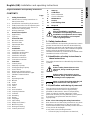
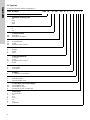
CONTENTS
Page
1. Safety instructions
These installation and operating instructions contain
general instructions that must be observed during
installation, operation and maintenance of the pump.
It must therefore be read by the installation engineer
and the relevant qualified operator prior to
installation and start-up, and must be available at the
installation location at all times.
1.1 Identification of safety instructions in
these instructions
The safety instructions are identified by the following
symbols:
1.2 Qualification and training of personnel
The personnel responsible for the installation,
operation and service must be appropriately
qualified for these tasks. Areas of responsibility,
levels of authority and the supervision of the
personnel must be precisely defined by the operator.
If necessary, the personnel must be trained
appropriately.
Risks of not observing the safety instructions
Non-observance of the safety instructions may have
dangerous consequences for the personnel, the
environment and the pump and may result in the loss
of any claims for damages.
It may lead to the following hazards:
• Personal injury from exposure to electrical,
1. Safety instructions
5
1.1 Identification of safety instructions in
these instructions
5
1.2 Qualification and training of personnel
5
1.3 Safety instructions for the operator/user
6
1.4 Safety of the system in the event of a
failure in the dosing pump
6
1.5 Dosing chemicals
6
2. General description
7
2.1 Applications
7
2.2 Type key
8
3. Technical data
9
3.1 Mechanical data
9
3.2 Electrical data
9
3.3 Input/output data
9
3.4 Dimensions
10
4. Installation
10
4.1 Safety instructions
10
4.2 Installation environment
10
4.3 Installation of pump
10
4.4 Installation example
11
4.5 Electrical connection
11
4.6 Connection overview
12
5. Functions
14
5.1 Control panel
14
5.2 Start/stop of pump
15
5.3 Priming/venting of pump
15
5.4 Level control
15
5.5 Diaphragm leakage sensor
15
5.6 Alarm output and indicator lights
16
5.7 Fieldbus communication
17
5.8 Menu
18
5.9 Operating modes
19
5.10 Manual
19
5.11 Pulse
19
5.12 Analog
20
5.13 Timer
21
5.14 Batch
22
5.15 Anti-cavitation
22
5.16 Capacity limitation
23
5.17 Counters
23
5.18 Resetting
24
5.19 Return
24
5.20 Language
24
5.21 Input setup
25
5.22 Empty tank (alarm)
26
5.23 Measuring units
26
5.24 Dosing monitoring
27
5.25 Control panel lock
28
6. Start-up
29
7. Calibration
30
7.1 Direct calibration
31
7.2 Check calibration
32
8. Maintenance
32
9. Service
32
10. Fault finding chart
33
11. Disposal
33
Warning
Prior to installation, read these
installation and operating instructions.
Installation and operation must comply
with local regulations and accepted
codes of good practice.
Warning
If these safety instructions are not
observed, it may result in personal
injury!
Caution
If these safety instructions are not
observed, it may result in malfunction
or damage to the equipment!
Note
Notes or instructions that make the job
easier and ensure safe operation.

English (GB)
6
mechanical and chemical influences.
• Damage to the environment and personal injury
from leakage of harmful substances.
1.3 Safety instructions for the operator/
user
The safety instructions described in these
instructions, existing national regulations on health
protection, environmental protection and for accident
prevention and any internal working, operating and
safety regulations of the operator must be observed.
Information attached to the pump must be observed.
Leakages of dangerous substances must be
disposed of in a way that is not harmful to the
personnel or the environment.
Damage caused by electrical energy must be
prevented, see the regulations of the local electricity
supply company.
Only orginal accessories and original spare parts
should be used. Using other parts can result in
exemption from liability for any resulting
consequences.
1.4 Safety of the system in the event of a
failure in the dosing pump
The dosing pump was designed according to the
latest technologies and is carefully manufactured
and tested.
If it fails regardless of this, the safety of the overall
system must be ensured. Use the relevant
monitoring and control functions for this.
1.5 Dosing chemicals
Caution
Before starting work on the pump, the
pump must be disconnected from the
mains. The system must be
pressureless!
Note
The mains plug is the separator
separating the pump from the mains.
Caution
Make sure that any chemicals that are
released from the pump or any
damaged lines do not cause damage to
system parts and buildings.
The installation of leak monitoring
solutions and drip trays is
recommended.
Warning
Before switching the supply voltage
back on, the dosing lines must be
connected in such a way that any
chemicals in the dosing head cannot
spray out and put people at risk.
The dosing medium is pressurised and
can be harmful to health and the
environment.
Warning
When working with chemicals, the
accident prevention regulations
applicable at the installation site
should be applied (e.g. wearing
protective clothing).
Observe the chemical manufacturer's
safety data sheets and safety
instructions when handling chemicals!
Caution
A deaeration hose, which is routed into
a container, e.g. a drip tray, must be
connected to the deaeration valve.
Caution
The dosing medium must be in liquid
aggregate state!
Observe the freezing and boiling points
of the dosing medium!
Caution
The resistance of the parts that come
into contact with the dosing medium,
such as the dosing head, valve ball,
gaskets and lines, depends on the
medium, media temperature and
operating pressure.
Ensure that parts in contact with the
dosing medium are resistant to the
dosing medium under operating
conditions, see data booklet!
Should you have any questions
regarding the material resistance and
suitability of the pump for specific
dosing media, please contact
Grundfos.

English (GB)
7
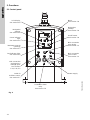
2. General description
The Grundfos DME dosing pump is a self-priming
diaphragm pump.
The pump consists of:
•a cabinet incorporating the drive unit and
electronics,
•a dosing head with back plate, diaphragm,
valves, connections and vent valve,
•a control panel incorporating display and
buttons. The control panel is fitted either to the
front or to the side of the cabinet.
The motor is controlled in such a way that the dosing
gets as even and constant as possible, irrespective
of the capacity range in which the pump is operating.
This is carried out as follows:
The speed of the suction stroke is kept constant and
the stroke relatively short, irrespective of the
capacity. Contrary to conventional pumps, which
generate the dosing stroke as a short pulse, the
duration of the dosing stroke will be as long as
possible. Thus, an even dosing without peak values
is ensured. As the pump is always dosing at full
stroke length, it ensures the same high accuracy and
suction capability, irrespective of the capacity, which
is infinitely variable in the ratio of 1:800.
The pump features an LCD display and a user-
friendly control panel which gives access to the
pump functions.
2.1 Applications
The DME dosing pump is designed for handling
chemicals within the following ranges of applications,
among others:
• drinking water treatment
• wastewater treatment
• cooling water treatment
• washing systems
• process water treatment
• chemical industry.

English (GB)
8
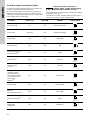
2.2 Type key
(Cannot be used for pump configuration.)
Code Example DME 60 - 10 AR - PP/ E/ C - F - 3 1 1 F
Pump range
Maximum capacity [l/h]:
60
150
375
940
Maximum pressure [bar]:
4
10
AR
AP
Control variant:
Standard
Standard + Profibus
PP
PV
SS
Dosing head material:
Polypropylene
PVDF
Stainless steel 1.4401
E
T
V
Gasket material:
EPDM
PTFE
FKM
C
G
SS
T
Valve ball material:
Ceramics
Glass
Stainless steel 1.4401
PTFE
F
S
Control panel:
Front-fitted
Side-fitted
3
Voltage:
1 x 100-240 V, 50-60 Hz
1
2
Valves:
Standard valve
Spring-loaded valve
A1
A2
Q
Connection, suction/discharge:
Threaded Rp 3/4
Threaded Rp 1 1/4
Tubing 19/27 mm + 25/34 mm
F
G
I
B
J
E
L
Mains plug:
EU (Schuko)
UK
AU
USA
JP
CH
Argentina

English (GB)
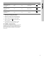
9
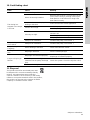
3. Technical data
3.1 Mechanical data
*
1
Irrespective of counter pressure
*
2
Maximum suction lift 1 metre
3.2 Electrical data
3.3 Input/output data
The pump offers various input and output options, depending on control variant.
DME 60 DME 150 DME 375 DME 940
Maximum capacity*
1
[l/h] 60 150 376 940
Maximum capacity with anti-cavitation 75 %*
1
[l/h] 45 112 282 705
Maximum capacity with anti-cavitation 50 %*
1
[l/h] 33.4 83.5 210 525
Maximum capacity with anti-cavitation 25 %*
1
[l/h] 16.1 40.4 101 252
Maximum pressure [bar] 10 4 10 4
Maximum stroke rate per minute [strokes/min.] 160
Maximum suction lift during operation [m] 4
Maximum suction lift when priming with wet valves [m] 1.5
Maximum viscosity with spring-loaded valves*
2
[mPa s] 3000 [mPa s] at 50 % capacity
Maximum viscosity without spring-loaded valves*
2
[mPa s] 200
Diaphragm diameter [mm] 79 106 124 173
Liquid temperature [°C] 0 to 50
Ambient temperature [°C] 0 to 45
Accuracy of repeatability ±1 %
Sound pressure level [dB(A)] <70
DME 60 DME 150 DME 375 DME 940
Supply voltage [VAC] 1 x 100-240 V
Maximum current consumption [A]
at 100 V 1.25 2.4
at 230 V 0.67 1.0
Maximum power consumption P
1
[W] 67.1 240
Frequency [Hz] 50-60
Enclosure class IP 65
Insulation class B
Supply cable 1.5 m H05RN-F with plug
Signal input
Voltage in level sensor input [VDC] 5
Voltage in pulse input [VDC] 5
Minimum pulse-repetition period [ms] 3.3
Impedance in analog 0/4-20 mA input []
The analog input requires a signal which is isolated from frame.
Min. resistance to frame: 50 k
250
Maximum loop resistance in pulse signal circuit [] 250
Maximum loop resistance in level signal circuit [] 250
Signal output
Maximum load of alarm relay output, at ohmic load [A] 2
Maximum voltage, alarm relay output [V] 42

English (GB)
10
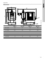
3.4 Dimensions
See dimensions at the end of these instructions.
All dimensions are in mm.
4. Installation
4.1 Safety instructions
• Liquid is under pressure and may be hazardous.
• When working with chemicals, local safety rules
and regulations must be observed (e.g. wear
protective clothes).
• Before starting work on the dosing pump and
system, disconnect the electricity supply to the
pump, ensuring that it cannot be accidentally
switched on. Before reconnecting the electricity
supply, make sure that the dosing hose is
positioned in such a way that any chemical left in
the dosing head is not ejected, thereby exposing
persons to danger.
• If the vent valve in the dosing head is used, it
must be connected to a hose which is led back to
the tank.
• When changing a chemical, make sure that the
materials of the dosing pump and system are
resistant to the new chemical. If there is any risk
of chemical reaction between the two types of
chemicals, clean the pump and system
thoroughly before adding the new chemical.
Proceed as follows:
Place the suction tube in water and press the
button until residual chemical has been removed.
Note: When the buttons and are pressed
simultaneously, the pump can be set to run for a
specific number of seconds at maximum
capacity. The remaining number of seconds will
appear in the display. The maximum value is
300 seconds.
4.2 Installation environment
• Exposure to direct sunlight should be avoided.
This applies especially to pumps with plastic
dosing heads, as this material can be damaged
by sunlight.
• If the pump is installed outside, an enclosure or
similar protection is required to protect the pump
against rain and similar weathers.
4.3 Installation of pump
• See also the installation example in section 4.4.
• Note: The dosing head may contain water from
the factory test. If a liquid which must not come
into contact with water is to be dosed, it is
recommended to let the pump run with another
liquid to remove the water from the dosing head
before installation.
• Always install the pump on the supporting foot
with vertical suction and discharge ports.
• Always use suitable tools for the mounting of
plastic parts. Never apply unnecessary force.
• Tighten the dosing head after 2 to 5 operating
hours (torque 5.5 Nm).
• Make sure that the dosing pump and system are
designed in such a way that neither system
equipment nor buildings are damaged in case of
leakage from the pump or rupture of hoses/pipes.
The installation of leakage hoses and collecting
tanks is recommended.
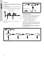
• Make sure that the drain hole in the dosing head
points downwards, see fig. 1.
Note: It is important that the drain pipe/hole is
not inserted direct into the tank contents, as
gasses may penetrate into the pump.
Fig. 1
100%
100%
TM02 7066 2503
Drain hole

English (GB)
11
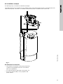
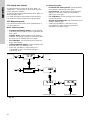
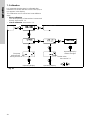
4.4 Installation example
The drawing in fig. 2 shows an installation example.
Fig. 2
4.5 Electrical connection
• The electrical connection of the pump should be
carried out by qualified persons in accordance
with local regulations.
• For electrical data of the pump, see section 3.2.
• Do not lay signal cables, if any, together with
power cables.
The DME pump can be installed in many different ways. The sketch below shows an example with side-
fitted control panel. The tank is a Grundfos chemical tank with a Grundfos level control unit.
TM02 7065 0604

English (GB)
12
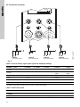
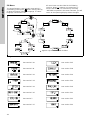
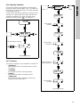
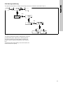
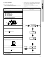
4.6 Connection overview
Fig. 3
Cable 1: Input for analog signal, pulse signal and diaphragm leakage
* Grundfos diaphragm leakage sensor, product number 96534443
Cable 2: Alarm relay output
TM02 7069 0307
Cable 1.
See table below
Cable 2.
See table below
Cable 3.
See table below
Cable 4.
See table below
2
1
3
4
5
3
1
4
2
3
1
2
3
1
5
2
5
2
2
3 1
1
3
4
5
2
1
3
4
2
1
3
4
Number / colour 1 / brown 2 / white 3 / blue 4 / black 5 / grey
Function
Analog
(–) 4-20 mA
input
(+) 4-20 mA
input
Pulse Potential-free Potential-free
Pulse 5 V Ground
Number / colour 2 / black 3 / brown 4 / blue
Diaphragm leakage* 5 V PNP Ground
Number / colour 1 / brown 2 / white 3 / blue
Function
Alarm relay Common Normally open Normally closed

English (GB)
13
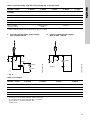
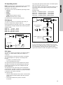
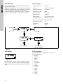
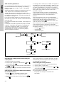
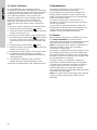
Cable 3: Input for dosing stop and dosing monitoring or dosing output
* Open collector (NPN) can be used for a relay or a lamp.
Fig. 4
Cable 4: Level input
* The function of the potential-free contact sets can
be selected via the control panel (NO = normally
open and NC = normally closed), see
section 5.21.
Number / colour 1 / brown 2 / white 3 / blue 4 / black 5 / grey
Function
Dosing stop (input) 5 V Ground
Dosing stop (input) Potential-free Potential-free
Dosing monitoring Potential-free Potential-free
Dosing monitoring Ground 5 V
Dosing output
(pump running)
Open collector
(NPN)*
Ground
1. Using the internal 5 VDC power supply:
Max. current: 100 mA
2. Using an external power supply:
Max. 24 VDC - 100 mA
TM03 7868 5006
TM03 7869 5006
Relay
Lamp
Power
Lamp
24 VDC
Number / colour 1 / brown 2 / white 3 / blue 4 / black
Function
Empty tank Potential-free* Potential-free*
Empty tank 5 V Ground
Low level Potential-free* Potential-free*
Low level 5 V Ground

English (GB)
14
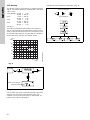
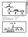
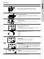
5. Functions
5.1 Control panel
Fig. 5
TM02 7068 2503
100%
LCD display.
See section 5.8
Navigation/
settings.
See section 5.8
Green indicator
light.
See section 5.6
Maximum capacity
(priming).
See section 5.3
Red indicator light.
See section 5.6
M12 connection
analog/pulse /
leakage input.
See sections
5.11, 5.12, 5.5
Cable for
Profibus control.
See section 5.7
Connection alarm
relay.
See section 5.6
Power supply
M12 connection
level control.
See section 5.4
M12 connection
stop dosing.
See section 5.2
On/off button.
See section 5.8
Navigation/
settings.
See section 5.8
Menu.
See section 5.8

English (GB)
15
5.2 Start/stop of pump
The pump can be started/stopped in two different
ways:
• Locally on the pump control panel.
• By means of an external on/off switch.
See connection overview in section 4.6.
5.3 Priming/venting of pump
The pump control panel incorporates a button.
Press this button if the maximum pump capacity is
required over a short period, e.g. during start-up.
When the button is released, the pump automatically
returns to the previous operating mode.
During priming/venting, it is recommended to let the
pump run without a counter pressure or to open the
vent valve.
Note: When the buttons and are pressed
simultaneously, the pump can be set to run for a
specific number of seconds at maximum capacity.
The remaining number of seconds will appear in the
display. The maximum value is 300 seconds.
5.4 Level control
The pump can be fitted with a level control unit for
monitoring of the chemical level in the tank.
The pump can react to two level signals. The pump
will react differently, depending on the influence on
the individual level sensors.
For connection of the level control unit and alarm
output, see section 4.6.
5.5 Diaphragm leakage sensor
The pump can be fitted with a diaphragm leakage
sensor, which detects diaphragm leakage.
The sensor should be connected to the drain hole in
the dosing head.
In case of diaphragm leakage, the signal from the
sensor generates an alarm and the alarm relay will
be activated. See also section 5.6.
For connection of the diaphragm leakage sensor,
see section 4.6.
Level sensors Pump reaction
Upper sensor
activated
(closed contact)
• Red indicator light is on.
• Pump running.
• Alarm relay activated.
Lower sensor
activated
(closed contact)
• Red indicator light is on.
• Pump stopped.
• Alarm relay activated.
100%
100%

English (GB)
16
5.6 Alarm output and indicator lights
The green and red indicator lights on the pump are
used for operating and fault indication.
In control variant "AR", the pump can activate an
external alarm signal by means of a built-in alarm
relay which must only be connected to a safety extra
low voltage (SELV) connection.
The alarm signal is activated by means of an internal
potential-free contact.
The functions of the indicator lights and the built-in
alarm relay appear from the table below.
Note
Connect the alarm relay only to
voltages which comply with the SELV
requirements in EN/IEC 60 335-1.
Condition Green LED Red LED Display Alarm output
Pump running On Off Normal indication
Set to stop Flashing Off Normal indication
Pump fault Off On EEPROM
Supply failure Off Off Off
Pump running, low
chemical level
1
On On LOW
Empty tank
1
Off On EMPTY
Analog signal
< 2 mA
Off On NO mA
The pump is
running, but the
dosed quantity is
too small according
to the signal from
the dosing
monitor
2
On On NO FLOW
Overheating Off On MAX. TEMP.
Internal
communication fault
Off On INT. COM.
Internal Hall fault
3
Off On HALL
Diaphragm
leakage
4
Off On LEAKAGE
1 32
NC NO C
1 32
NC NO C
1
2 3
NC NO C
1 32
NC NO C
1
2 3
NC NO C
1
2 3
NC NO C
1
2 3
NC NO C
1
2 3
NC NO C
1
2 3
NC NO C
1
2 3
NC NO C
1
2 3
NC NO C
1
2 3
NC NO C

English (GB)
17
1
Requires connection to level sensors.
See section 5.22 Empty tank (alarm).
2
Requires activation of the dosing monitoring
function and connection to a dosing monitor.
3
Please contact a Grundfos service centre.
4
Alarms can be reset when the faults have
been corrected.
5
The pump will make 10 attempts to restart
before going into permanent OFF mode.
5.7 Fieldbus communication
The pump can be configured for fieldbus applications
(Profibus). Apart from the usual installation and
operating instructions, Profibus pumps are supplied
with a special Profibus installation and operating
instructions.
Maximum pressure
exceeded
4
Off
5
On OVERLOAD
More pulses than
capacity
On On MAX. FLOW
No motor rotation
detected
3
Off On ORIGO
Condition Green LED Red LED Display Alarm output
1
2 3
NC NO C
1
2 3
NC NO C
1
2 3
NC NO C

English (GB)
18
5.8 Menu
The pump features a user-friendly menu which is
activated by pressing the button. During start-up,
all texts will appear in English language. To select
language, see section 5.20.
All menu items are described in the following
sections. When appears at a menu item, it
means that this item is activated. By selecting
"RETURN" anywhere in the menu structure, you will
return to the operating display without changes.
Fig. 6
Applies only to versions with Profibus
See section 5.10 See section 5.25
See section 5.11 See section 5.18
See section 5.12 See section 5.19
See section 5.13 See section 5.20
See section 5.14 See section 5.16
See section 5.15 See section 5.21
See section 7. See section 5.22
See section 5.17 See section 5.23

English (GB)
19
5.9 Operating modes
Note: The displayed l and ml values are only reliable
if the pump has been calibrated to the actual
installation, see section 7.
The pump can run in five different operating modes:
•Manual
•Pulse
•Analog
• Timer (internal batch control)
• Batch (external batch control)
See description in the following sections.
5.10 Manual
The pump is dosing as constantly and evenly as
possible, without any external signals.
Set the quantity to be dosed in l/h or ml/h. The pump
automatically changes between the measuring units.
Setting range:
DME 60: 75 ml/h - 60 l/h
DME 150: 200 ml/h - 150 l/h
DME 375: 500 ml/h - 375 l/h
DME 940: 1200 ml/h - 940 l/h
Fig. 7
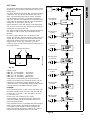
5.11 Pulse
The pump is dosing according to an external pulse
signal, i.e. a water meter with pulse output or a
controller.
Set the quantity to be dosed per pulse in ml/pulse.
The pump adjusts its capacity according to two
factors:
• Frequency of external pulses.
• The set quantity per pulse.
The pump measures the time between two pulses
and then calculates the speed giving the capacity
required (set quantity per pulse multiplied by the
pulse frequency).
The pump does not start until it has received the
second pulse, and thus it delivers a constant flow as
in the case of "manual" control. The pump calculates
a speed for each pulse received.
The pump stops
• when the time between two pulses is three times
longer than the time between the two previous
pulses, or
• if the time between two pulses exceeds
2 minutes.
The pump will operate at the latest calculated speed
until one of the two cases occurs.
The pump stops at the point reached in its duty cycle
and starts at this point again having received two
new pulses.
Setting range:
DME 60: 0.000625 ml/pulse - 120 ml/pulse
DME 150: 0.00156 ml/pulse - 300 ml/pulse
DME 375: 0.00392 ml/pulse - 750 ml/pulse
DME 940: 0.00980 ml/pulse - 1880 ml/pulse
Fig. 8
If the set quantity per pulse multiplied by the pulse
frequency exceeds the pump capacity, the pump will
run at maximum capacity. Excess pulses will be
ignored and "MAX. FLOW" will appear in the display.
Set value
Set quantity in
ml/pulse
Actual capacity in
ml/h or l/h

English (GB)
20
5.12 Analog
The pump is dosing according to an external analog
signal. The dosed quantity is proportional to the input
value in mA.
4-20 (default): 4 mA = 0 %.
20 mA = 100 %.
20-4: 4 mA = 100 %.
20 mA = 0 %.
0-20: 0 mA = 0 %.
20 mA = 100 %.
20-0: 0 mA = 100 %.
20 mA = 0 %.
See fig. 9.
The capacity limitation will influence the capacity.
100 % corresponds to the maximum capacity of the
pump or the set maximum capacity, see section 5.16.
The analog input requires a signal which is isolated
from frame. Min. resistance to frame: 50 k
Fig. 9
Fig. 10
If 4-20 mA or 20-4 mA is selected and the signal falls
below 2 mA, the pump will indicate a fault. This
situation occurs if the connection is interrupted, for
instance if the wire is damaged.
Change the analog mode as illustrated in fig. 11:
Fig. 11
TM02 4498 1102
0 4 8 12 16 20
0
20
40
60
80
100
[%]
0-20 mA
[mA]
4-20 mA
Value according to
analog signal
Use the buttons
for navigation
Page is loading ...
Page is loading ...
Page is loading ...
Page is loading ...
Page is loading ...
Page is loading ...
Page is loading ...
Page is loading ...
Page is loading ...
Page is loading ...
Page is loading ...
Page is loading ...
Page is loading ...
Page is loading ...
Page is loading ...
Page is loading ...
Page is loading ...
Page is loading ...
-
 1
1
-
 2
2
-
 3
3
-
 4
4
-
 5
5
-
 6
6
-
 7
7
-
 8
8
-
 9
9
-
 10
10
-
 11
11
-
 12
12
-
 13
13
-
 14
14
-
 15
15
-
 16
16
-
 17
17
-
 18
18
-
 19
19
-
 20
20
-
 21
21
-
 22
22
-
 23
23
-
 24
24
-
 25
25
-
 26
26
-
 27
27
-
 28
28
-
 29
29
-
 30
30
-
 31
31
-
 32
32
-
 33
33
-
 34
34
-
 35
35
-
 36
36
-
 37
37
-
 38
38


Grundfos DME 375 Installation And Operating Instructions Manual
- Type
- Installation And Operating Instructions Manual
- This manual is also suitable for
Ask a question and I''ll find the answer in the document
Finding information in a document is now easier with AI
Related papers
-
Grundfos DME 375 Installation And Operating Instructions Manual
-
Grundfos DMS 4 Installation And Operating Instructions Manual
-
Grundfos DME 2 Installation And Operating Instructions Manual
-
-
-
Grundfos CU 401 Installation And Operating Instructions Manual
-
-
-
-
Other documents
-
Liquid Fence HG-266 Installation guide
-
ProMinent Sigma/ 2 Control S2Cb Operating Instructions Manual
-
-
-
-
ProMinent Hydro HP4 Operating Instructions Manual
-
eta T AC Operating instructions
-
-
Hanna Instruments BL7916-1,BL7917-1 Owner's manual
-
Omega PHP-200 Series Owner's manual