
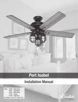
Installation Manual
©2020 Hunter Fan Co.
Model: 59261 Premier Bronze
59262 Matte Silver
59263 Fresh White
59264 Matte Black
Fan weight ±2 lbs: 13.6 lbs (6.2 kg)
Cassius
PG3922 r082620
Pull Chain w/LIGHT or Remote not button w/ NO LIGHT or Remote no button w/ LIGHT

1886
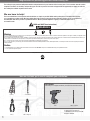
Ladder
9/64” Drill BitDrill
Screwdriver
Pliers
Wire Strippers
OPTIONAL
If mounting to a support structure, you will also need these tools.
Congratulations on purchasing your new Hunter
®
ceiling fan!
Here are the tools you’ll need to complete your installation:
1
The ceiling fan you purchased will provide comfort and performance in your home or ofce for many years. This instruction manual contains
complete instructions for installing and operating your fan. We are proud of our work and appreciate the opportunity to supply you with the
best ceiling fan available anywhere in the world.
We are here to help!
This Instruction Manual is designed to make installation as simple as possible. While working through this Instruction Manual, keep
your smartphone or tablet nearby. We have added video links to help you through the more technical sections. If you are unfamiliar or
uncomfortable with wiring, contact a qualied electrician. We also provide telephone support at 1.888.830.1326 or visit us
at HunterFan.com.
WARNING
READ and SAVE These Instructions
Warning
w.1 - To reduce the risk of re, electrical shock, or personal injury, mount fan directly from building structure and/or an outlet box marked acceptable for fan support of 70 lbs (31.8 kg) and use the
mounting screws provided with the outlet box.
w.2 - To avoid possible electrical shock, before installing or servicing your fan, disconnect the power by turning off the circuit breakers to the outlet box and associated wall switch location. If you
cannot lock the circuit breakers in the off position, securely fasten a prominent warning device, such as a tag, to the service panel.
w.3 – To reduce the risk of electric shock, this fan must be installed with an isolating wall control/switch.
w.4 - To reduce the risk of personal injury, do not bend the blade brackets when installing the blade brackets, balancing the blades, or cleaning the fan. Do not insert foreign objects in between
rotating fan blades.
Caution
c.1 - All wiring must be in accordance with national and local electrical codes ANSI/NFPA 70. If you are unfamiliar with wiring, use a qualied electrician.
c.2 - Use only Hunter replacement parts.
This product conforms to UL Standard 507.
© 2020 Hunter Fan Company
7130 Goodlett Farms Pkwy, Suite 400
Memphis TN 38016

PB
2
1886
1886
Do not discard the hardware bags or mix parts from
different bags. Make note of the symbol printed on
each hardware bag. The symbols can be used to
identify the appropriate hardware for each step.
We recommend that you pull everything out of the box and lay it out. We have
grouped the drawn components below with the hardware you’ll need for those
parts. The screws below are drawn to scale to make it easier to identify what
piece of hardware is needed to install each component.
x4
x2
x2
x2
For installing the hanger bracket and wiring the fan
For installing the canopy
Canopy
Canopy Screw
Ceiling Bracket
Wood Screw
Wire Nut
Washer
bag
Hunter Pro Tip:
Find a part that is missing or damaged?
Don’t take it back to the store. Let us make it right. Visit us at HunterFan.com or call us at 1.888.830.1326.
Here is what comes in your box:
bag
Spare Parts
For your convenience,
you may receive extra fasteners.
Pullchain and downrod
bag
M3828-01 r081020
For installing the blades
For installing upper assembly
Cap
Motor cover
Motor
Upper assembly
Blade
Blade Iron
Downrod
x3
x3
x9
x6
bagbag
Blade Screw
Blade Iron Screw
x9
bag
Blade Nut
x3
Upper Switch
Housing Screw
bag
x3
x3
Short Upper
Switch Housing
Screw
Top Housing
Screw
bag
Fan style may vary.
Note:

3
4
1886
1886
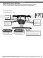
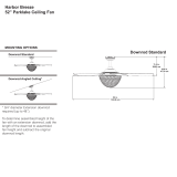
Choosing the Right Installation Location
Checking the Ceiling Angle:
Angled Mounting
You probably bought this fan with a location in mind. Let’s check below to make sure it is a good t.
If you have an angled or vaulted ceiling:
1. You will need a longer downrod. (sold separately at HunterFan.com)
2. If your ceiling angle is greater than 34°, you will also need an
Angled Mounting Kit. (Sold separately at HunterFan.com)
Check the room dimensions: Check the outlet box:
You must be able to
secure the fan to building
structure or fan-rated
outlet box.
30 inches
from blade tip to
nearest wall or
obstruction
7 feet
from bottom edge
of blade to the
oor
Support
Structure
Ceiling
Outlet Box
(required)
Angled Mounting
If you have a at ceiling:
Hang your fan by a standard downrod. Some fans come
with a shorter downrod for a Low Prole installation.
Support Structure
Ceiling
Outlet Box
(required)
Standard Mounting
A little more information on Angled Mounting:
For optimum performance and appearance, a longer downrod should
be used with your Hunter ceiling fan when installing on high or angled
ceiling. If your ceiling is angled greater than 34° you will also need an
Angled Mounting Kit. Longer downrods and the Angled Mounting Kit are
sold separately at HunterFan.com.
Determining if you need an Angled Mounting Kit:
Fold on the dotted line. Place against edge againts
the wall. Slide towards the ceiling.
If the guide touches the wall but not the ceiling, you
need an angled mounting kit.
Hunter Pro Tip:
CEILING
WALL
34°
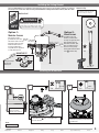
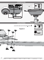
Installing the Ceiling Bracket
Installing the Blade Irons

3
4
1886
1886
Check the outlet box:
Installing the Ceiling Bracket
Installing the Blade Irons
Use wood screws and
washers (included) when
securing to support structure
with approved electrical
outlet box. Drill 9/64” pilot
holes in support structure
to aid in securing ceiling
bracket with hardware found
in the hardware bag.
Use machine screws
(provided with outlet box)
and washers when securing
to existing ceiling fan-rated
outlet box. Make sure it is
securely installed and is
acceptable for fan support of
31.8 kg (70 lbs) or less.
Option 2:
Wood Screws
Option 1:
Machine Screws
OFF
Turn Power
Do this rst!
The machine screws are the ones
that came with your outlet box.
Hunter Pro Tip:
For angled ceilings,
point opening
toward peak.
ANGLED
MOUNTING TIP
bag
Wood Screw
Washer
x2
x2
You have two options for installation. Pick which one works best for your location. Remove any existing
bracket prior to installation. Only use the provided Hunter ceiling bracket that came in your fan’s box.
K
E
E
P
!
1
STEP
Remove the pre-installed
setscrew so that the
downrod can be inserted.
Lightly attach blade irons to the motor with screws found
in the hardware bag , then securely tighten after
screws are attached.
6 of 6
Blade Iron Screw
bag
2
STEP
Ceiling Bracket Downrod Hanging Fan Wiring Canopy Blades Upper Switch Housing Reverse
Lower the top housing onto the top of the motor.
Install the three top housing screws found in the
hardware bag.
3 of 3
Top Housing Screw
3
STEP
bag
Fan style may vary.
Note:
WARNING
To avoid possible electrical shock, before
installing your fan, disconnect the power by
turning off the circuit breakers to the outlet
box associated with the wall switch location.

5
6
1886
1886
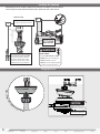
Hanging the Fan
S
l
i
d
e
c
a
n
o
p
y
o
v
e
r
d
o
w
n
r
o
d
a
n
d
w
i
r
e
s
.
Place the downrod ball into
the slot in the ceiling bracket.
NOTICE
To prevent damage to fan,
ALWAYS lift holding either the
fan housing or the downrod.
Wiring the Fan
Installing the Downrod
Follow below if you are using the downrod that came pre-assembled in your box. Need to
install a longer or shorter downrod? Check out the guide at the end of this manual.
8”
3/8”
C
U
T
&
S
T
R
I
P
(not to scale)
Pass all wires to one side of horizontal
bar in downrod assembly. Hand tighten
the downrod (at least 4–5 full turns)
until it stops. Trim the wires coming
from the fan so that 8-inches remain
coming from the top of the downrod.
Tighten the setscrew
with pliers. DO NOT
HAND TIGHTEN.
1
2
STEP
STEP
Hunter Pro Tip:
The ground wire attached to the
downrod is approximately 8 inches.
WARNING
FAN FALL HAZARD
To prevent SERIOUS INJURY or DEATH:
• ALWAYS tighten setscrew with pliers.
• DO NOT hand tighten setscrew.
• CHECK the setscrew is tight using pliers
each time you change fan direction.
Ceiling Bracket Downrod Hanging Fan Wiring Canopy Blades Upper Switch Housing Reverse

5
6
1886
1886
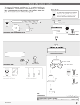
Wiring the Fan
We know wiring is hard. Let’s make it easier.
You are going to need these:
4 Wire Nuts (these are in the bag)
Follow these steps to get your fan wired quickly and safely. Follow the route below that best matches your wall switch
setup. If you are unfamiliar with wiring or uncomfortable doing it yourself, please contact a qualied electrician.
Connect the white
(grounded) wire
from the ceiling
to the white wire
from the fan.
Connect the three
grounding wires (green,
green/yellow stripe, or
bare copper) coming from
the ceiling, downrod, and
hanging bracket.
Green/Yellow Stripe
White
Grounded
Grounding
G
r
e
e
n
/
Y
e
l
l
o
w
S
t
r
i
p
e
x4
bag
Wire Nut
Connect the black wire
(ungrounded) from the
ceiling to the black and the
blue wires from the fan.
Black
Blue
WARNING
All wiring must be in accordance with
national and local electrical codes ANSI/NFPA
70. If you are unfamiliar with wiring or in
doubt, consult a qualied electrician.
Installing the Downrod
Ceiling Bracket Downrod Hanging Fan Wiring Canopy Blades Upper Switch Housing Reverse
WARNING
The ceiling fan must be grounded. If the
ground wire for the installation site is not
present, immediately STOP installation and
consult a qualied electrician.
Have extra wiring?
Turn the wires upward and push them carefully back through
the hanger bracket into the outlet box. Spread the wires apart,
with the grounded wires on one side of the outlet box and the
ungrounded wires on the other side of the outlet box. Make
sure that the wires are still attached to the wire nuts.
Hunter Pro Tip:

7
8
1886
1886
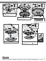
Installing the Blades:
Assembling the Light Fixture
Installing the Canopy
x2
Lift the canopy into place so that
the screw holes are aligned.
Insert the two canopy screws
found in the hardware bag.
F
i
t
t
h
e
c
a
n
o
p
y
i
n
p
l
a
c
e
a
s
s
h
o
w
n
.
bag
Canopy Screw
Secure each blade to a blade iron as shown using the blade nuts, found in the
hardware bag, and the blade assembly screws, found in the hardware bag.
Repeat x3
x9
bag
Blade Screw
x9
bag
Blade nut
Ceiling Bracket Downrod Hanging Fan Wiring Canopy Blades Upper Switch Housing Reverse

7
8
1886
1886
Assembling the Light Fixture
Align the keyhole
slots in the top
of the light kit
assembly with the
partially installed
assembly screws.
Wrap the keyhole
slots around the
screws and twist
counterclockwise.
Partially install two light kit assembly screws, found
in the hardware bag, halfway into the motor
housing as shown. It does not matter which two
screw holes you choose.
WARNING
FAN FALL HAZARD
Make sure all three screws are tight to secure
the trim ring to the mounting plate.
2 of 3
Light Kit Screw
bag
1 of 3
Light Kit Screw
bag
Insert the third screw, found in the
hardware bag, into place and then tighten all
three screws.
Feed the wire plug through the center hole of the upper
switch housing, then wrap keyhole slots around the
screws and twist counterclockwise.
3 of 3
Light Kit Screw
bag
Connect the plugs from the upper and lower switch housings.
Make sure to line up the colored markings on the connectors.
Lift the lower switch housing until its screw holes are aligned
with the screw holes in the upper switch housing. Install the
three switch housing screws, found in the hardware bag.
Tighten all three screws.
ON
Turn Power
Ceiling Bracket Downrod Hanging Fan Wiring Canopy Blades Upper Switch Housing Reverse
Fan style may vary.
Note:

9
10
1886
1886
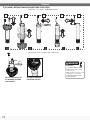
Installing Pullchain
Reversing the Fan
Installing the pull chain pendant - Attach the pull chain pendant to the
short chain coming from the switch housing.
Reverse
Switch
Ceiling fans work in two directions: downdraft
(counterclockwise rotation) and updraft
(clockwise rotation). To change the direction
of air ow, turn the fan off and let it come to a
complete stop. Slide the reversing switch to the
opposite position. Restart the fan.
Updraft (clockwise rotation)
creates a more indirect airow.
Updraft airow is great for
moving warm air downward.
Downdraft (counterclockwise
rotation) creates a direct breeze
and maximum cooling effect.
Ceiling Bracket Downrod Hanging Fan Wiring Canopy Blades Upper Switch Housing Reverse
Fan style may vary.
Note:
Fan style may vary.
Note:

9
10
1886
1886
Troubleshooting
Fan Doesn’t Work
• Make sure power switch is on.
• Pull the pull chain to make sure it is on.
• Push the motor reversing switch rmly left or right to
ensure that it is engaged.
• Check the circuit breaker to ensure the power is
turned on.
• Make sure the blades spin freely.
• Turn off power from the circuit breaker, then loosen
the canopy and check all the connections according
to the wiring diagram.
• Check the plug connection in the switch housing.
Excessive Wobbling
• Make sure the blades are properly installed on the
blade iron posts.
• Turn the power off, support the fan carefully, and
check that the hanger ball is properly seated.
• Use the provided balancing kit and instructions to
balance the fan.
Noisy Operation
• Make sure the blades are properly installed.
• Check to see if any of the blades are cracked. If so,
replace all of the blades.
Cleaning the Fan
Use soft brushes or cloths to prevent scratching.
Cleaning products may damage the nishes.
Hunter Pro Tip:
Hunter Fan Company grants this limited warranty to the original purchaser of this Hunter
ceiling fan. This document can be found at www.HunterFan.com.
Thank you for choosing Hunter!
How Can Warranty Service Be Obtained?
Proof of purchase is required when requesting warranty service. The original
purchaser must present a sales receipt or other document that establishes proof of
purchase. Hunter, at its sole discretion, may accept a gift receipt. To obtain service,
contact Hunter Fan Company online or by phone.
www.HunterFan.com/Support/Contact-Us/
1-888-830-1326
Please do not ship your fan or any fan parts to Hunter. Delivery will be refused.
What Does This Warranty Cover?
Motor — Limited Lifetime Warranty
If any part of your ceiling fan motor fails during your ownership of the fan due to a
defect in material or workmanship, as determined solely by Hunter, Hunter will provide
you with a replacement fan free of charge.* The foregoing limited warranty applies only
to the motor itself and does not apply to electronic controls – such as remote control
transmitters, remote control receivers, or capacitors – used in conjunction with the
motor. Such electronic control items are included in the one-year limited warranty below.
Other — One-Year Limited Warranty
Except as otherwise indicated throughout this warranty, if any part of your Hunter ceiling
fan fails at any time within one year of the date of purchase due to a defect in material
or workmanship, as determined solely by Hunter, Hunter will provide a replacement part
free of charge.*
Light Kits — Warranty May Vary
Light kits are included in the one-year limited warranty. However, you may qualify for
additional warranty coverage if your fan includes one of the following:
• LED Light Kits — Three-Year Limited Warranty
If your LED light kit module (not including glass components) or LED bulb
fails at any time within three years of the date of purchase due to a defect
in material or workmanship, as determined solely by Hunter, Hunter will
provide a replacement part free of charge.*
* If no replacement product/part can be provided for your fan, we will provide a comparable or
superior replacement product/part at the sole discretion of Hunter.
What Does This Warranty NOT Cover?
Labor Excluded. This warranty does not cover any costs or fees associated with the labor
(including electrician’s fees) required to install, remove, or replace a fan or any fan parts.
There is no warranty for light bulbs (except where otherwise noted); remote control
batteries; fans purchased or installed outside the United States; fans owned by
someone other than the original purchaser; fans for which proof of purchase has not
been established; fans purchased from an unauthorized dealer; ordinary wear and tear;
minor cosmetic blemishes; refurbished fans; and fans that are damaged due to any
of the following: improper installation, misuse, abuse, improper care, failure to follow
Hunter instructions, accidental damage caused by the fan owner or related parties,
modications to the fan, improper or incorrectly performed maintenance or repair,
improper voltage supply or power surge, use of improper parts or accessories, failure to
provide maintenance to the fan, or acts of God (e.g. ood).
ORIGINAL PURCHASER’S SOLE AND EXCLUSIVE REMEDY FOR A CLAIM OF ANY KIND
WITH RESPECT TO THIS PRODUCT SHALL BE THE REMEDIES SET FORTH HEREIN.
HUNTER FAN COMPANY IS NOT RESPONSIBLE FOR CONSEQUENTIAL OR INCIDENTAL
DAMAGES, DUE TO PRODUCT FAILURE, WHETHER ARISING OUT OF BREACH OF
WARRANTY, BREACH OF CONTRACT, OR OTHERWISE. Some States do not allow the
exclusion or limitation of incidental or consequential damages, so the above limitation or
exclusion may not apply to you.
ANY IMPLIED WARRANTIES OF MERCHANTABILITY OR FITNESS FOR A PARTICULAR
PURPOSE APPLICABLE TO THIS PRODUCT ARE LIMITED IN DURATION TO THE PERIOD OF
COVERAGE OF THE APPLICABLE LIMITED WARRANTIES SET FORTH ABOVE. Some States
do not allow limitations on how long an implied warranty lasts, so the above limitation
may not apply to you.
How Does State Law Affect Warranty Coverage?
This warranty gives you specic legal rights. You may also have other rights which vary
from state to state.
Limited Lifetime Warranty

11
PB
1886
1886
Downrod
If you need a different downrod length follow these steps:
Assembled downrod
should look like this
Here is another view of
the downrod assembly
unassembled.
Follow steps 1-5 to remove standard downrod pipe
Follow steps 6-10 to reassemble with new downrod
1 2 3 4 5
678910
1
10
9
2
7
4
8 3
65
Pin
Pin
WARNING
FAN FALL HAZARD
To prevent SERIOUS INJURY or DEATH:
• ALWAYS follow the downrod assembly
instructions exactly.
• VERIFY the downrod is assembled correctly
by rmly pulling on the hanger ball.
• Pin must be reinserted to secure
downrod assembly.
-
 1
1
-
 2
2
-
 3
3
-
 4
4
-
 5
5
-
 6
6
-
 7
7
-
 8
8
-
 9
9
-
 10
10
-
 11
11
-
 12
12


Ask a question and I''ll find the answer in the document
Finding information in a document is now easier with AI
Related papers
-
Hunter Mosley 50962 User manual
-
Hunter 50812 Presto 52 Inch Ceiling Fan User manual
-
 Hunter Fan 50810 Owner's manual
-
Hunter Fan 59610 Owner's manual
-
Hunter Fan 59472 Owner's manual
-
 Hunter Fan 50686 Owner's manual
-
 Hunter Fan 50780 User manual
-
Hunter Fan 51097 Owner's manual
-
 Hunter Fan 50991 Owner's manual
-
 Hunter Fan 51199 Owner's manual


Other documents
-
 Hunter Fan 50494 Owner's manual
-
 Harbor Breeze 00598 Dimensions Guide
-
 Harbor Breeze 00878 Dimensions Guide
-
Waddell 1372 Installation guide
-
 Hunter Fan 53411 Owner's manual
-
 Hunter Fan 53447 Owner's manual
-
 Hunter Fan 51624 Owner's manual
-
 Hunter Fan 50606 Owner's manual
-
Hunter Fan 54095 Owner's manual
-
 Hunter Fan 51237 Owner's manual


