AFG2021
Arbitrary Function Generator
Specifications and Performance Verification
ZZZ
Technical Reference
xx
www.tektronix.com
*
P077058801*
077-0588-01

Copyright © Tektronix. All rights reserved. Licensed software products are owned by Tektronix or its subsidiaries
or suppliers, and are protected by national copyright laws and international treaty provisions.
Tektronix products are covered by U.S. and foreign patents, issued and pending. Information in this publication
supersedes that in all previously published material. Specifications and price change privileges reserved.
TEKTRONIX and TEK are registered trademarks of Tektronix, Inc.
Additional trademark statements can be added here.
Contacting Tektronix
Tektronix, Inc.
14150 SW Karl Braun D rive
P.O. Box 5 0 0
Beaverton, OR 97077
USA
For product information, sales, service, and technical support:
In North America, call 1-800-833-9200.
Worldwide, visit www.tektronix.com to find contacts in your area.

Warranty
Tektronix warrants that this product will be free from defects in materials and workmanship for a period of one (1)
year from the date of shipment. If any such product proves defective during this warranty period, Tektronix, at its
option, either will repair the defective product without charge for parts and labor, or will provide a replacement
in exchange for the defective product. Parts, modules and replacement products used by Tektronix for warranty
work may be n
ew or reconditioned to like new performance. All replaced parts, modules and products become
the property of Tektronix.
In order to o
btain service under this warranty, Customer must notify Tektronix of the defect before the expiration of
the warranty period and make suitable arrangements for the performance of service. Customer shall be responsible
for packaging and shipping the defective product to the service center designated by Tektronix, w ith shipping
charges prepaid. Tektronix shall pay for the return o f the product to Customer if the shipment is to a location within
the country in which the Tektronix service center is located. Customer shall be responsible for paying all shipping
charges, duties, taxes, and any other charges for products returned to any other locations.
This warranty shall not apply to any defect, failure or damage caused by improper u se or improper or inadequate
maintenance and care. Tektronix shall not be obligated to furnish service under this warranty a) to repair damage
result
ing from attempts by personnel other than Tektronix representatives to install, repair or service the product;
b) to repair damage resulting from improper use or connection to incompatible equipment; c) to repair any damage
or malfunction caused by the use of non-Tektronix supplies; or d) to service a product that has been modified or
integrated with other products when the effect of such modification or integration increases the time or difficulty
of servicing the product.
THIS WARRANTY IS GIVEN BY TEKTRONIX WITH RESPECT TO THE PRODUCT IN LIEU OF ANY
OTHER WARRANTIES, EXPRESS OR IMPLIED. TEKTRONIX AND ITS VENDORS DISCLAIM ANY
IMPLIED WARRANTIES OF MERCHANTABILITY OR FITNESS FOR A PARTICULAR PURPOSE.
TEK
TRONIX' RESPONSIBILITY TO REPAIR OR REPLACE DEFECTIVE PRODUCTS IS THE SOLE
AND EXCLUSIVE REMEDY PROVIDED TO THE CUSTOMER FOR BREACH OF T HIS WARRANTY.
TEKTRONIX AND ITS VENDORS WILL NOT BE LIABLE FOR ANY INDIRECT, SPECIAL, INCIDENTAL,
OR CONSEQUENTIAL DAMAGES IRRESPECTIVE OF WHET HER TEKTRONIX OR THE VENDOR HAS
ADVANCE NOTICE OF THE POSSIBILITY OF SUCH DAMAGES.
[W2 – 15AUG04]


Ta ble of Contents
General safety summary .......................................................................................... iv
Service safety summary............................................................................................ 1
Preface ............................................................................................................... 3
Finding oth
er information..................................................................................... 3
Manual conventions ........................................................................................... 4
Specifications ....................................................................................................... 5
Electrical specifications ....................................................................................... 5
Input and output specifications .............................................................................. 10
General specifications ........................................................................................ 11
Perform
ance verification.......................................................................................... 13
Self tests ....................................................................................................... 13
Error codes .................................................................................................... 15
Performance tests ............................................................................................. 16
Test record ..................................................................................................... 18
Frequency/Period test ........................................................................................ 22
Ampl
itude test................................................................................................. 23
DC offset test.................................................................................................. 25
AC flatness test................................................................................................ 26
Harmonics distortion test .................................................................................... 28
Total harmonic distortion test ............................................................................... 29
Spurious test................................................................................................... 32
Ri
se-Fall time test............................................................................................. 34
AFG2021 Arbitrary Function Generator Specifi cations and Performance Verification i

Table of Contents
List of Figure
s
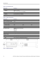
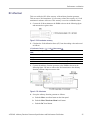
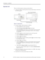
Figure 1: AFG2021 dimensions ................................................................................. 12
Figure 2: Fr
equency/Period tests ................................................................................ 22
Figure 3: 50 Ω terminator accuracy ............................................................................. 23
Figure 4: Amplitude tests......................................................................................... 24
Figure 5: 50 Ω terminator accuracy ............................................................................. 25
Figure 6: DC offset tests.......................................................................................... 25
Figure 7: AC flatness tests........................................................................................ 26
Figure 8:
Harmonic distortion tests.............................................................................. 28
Figure 9: Total harmonic distortion tests ....................................................................... 29
Figure 10: Spurious tests ......................................................................................... 32
Figure 11: Rise-Fall time tests ................................................................................... 34
ii AFG2021 Arbitrary Function Generator Specifications and Performance Verification

Table of Contents
List of Tables
Table 1: Operating mode .......................................................................................... 5
Table 2: Wav
eforms................................................................................................ 5
Table 3: Frequency/Period......................................................................................... 6
Table 4: Phase (except DC, noise, and pulse) ................................................................... 6
Table 5: Lead delay (pulse)........................................................................................ 6
Table 6: Amplitude................................................................................................. 7
Table 7: DC offset .................................................................................................. 7
Table 8: I
nternal noise add ........................................................................................ 7
Table 9: Output characteristics.................................................................................... 8
Table 10: Modulation .............................................................................................. 9
Table 11: Front panel.............................................................................................. 10
Table 12: Rear panel .............................................................................................. 11
Table 13: Power ................................................................................................... 11
Table
14: Export control.......................................................................................... 11
Table 15: Environmental ......................................................................................... 11
Table 16: System characteristics................................................................................. 12
Table 17: Error codes ............................................................................................. 15
Table 18: Performance test items ................................................................................ 16
Table 19: Test equipment ......................................................................................... 17
Ta
ble 20: Series Performance Test Record ..................................................................... 19
AFG2021 Arbitrary Function Generator Specifi cations and Performance Verification iii

General safety s ummary
General safet
ysummary
Review the fo
llowing safety precautions to avoid injury and prevent damage to
this product or any products connected to it.
To avoid pot
ential hazards, use this product only as specified.
Only qualified personnel should perform service procedures.
While using this product, you may need to access other parts of a larger system.
Read the safety sections of the other component manuals for warnings and
cautions r
elated to operating the system.
To avoid fi re or personal
injury
Use proper power cord. Use only the power cord speci fi ed for this product and
certified for the country of use.
Ground the product. This product is grounded through the grounding conductor
of the power cord. To a void electric shock, the grounding conductor must be
connected to earth ground. Before making connections to the input or output
terminals of the product, ensure that the product is properly grounded.
Observe all terminal ratings. To avoid fire or shock hazard, observe all ratings
and markings on the product. Consult the product manual for further ratings
information before making connections to the product.
Do not apply a potential to any terminal, including the common terminal, that
exceeds the maximum rating of that terminal.
Power d isconnect. The power cord disconnects the product from the power source.
Donotblockthepowercord;itmustremain accessible to the user at all times.
Do not operate without covers. Do not operate this product with covers or panels
removed.
Do not operate with suspected failures. If you suspect that there is damage to this
product, have it inspected by qualified service personnel.
Avoid exposed circuitry. Do not touch exposed connections and components when
power is present.
Do not operate in wet/damp conditions.
Do not operate in an explosive atmosphere.
Keep product surfaces clean and dry.
Provide p roper ventilation. Refer to the manual's installation instructions for details
on installing the product so it has proper ventilation.
iv AFG2021 Arbitrary Function Generator Specifications and Performance Verification

General safety summary
Terms in this manual
These ter ms may
appear in this manual:
WARNING. Warning statements identify conditions or practices that could result
in injury or loss of life.
CAUTION. Caution statements identify conditions or practices that could result in
damage to this product or other property.
Symbols and terms on t he
product
These terms may a ppear on the product:
DANGER in
dicates an injury hazard immediately accessible as you read
the marking.
WARN IN G
indicates an injury hazard not immediately accessible as you
read the marking.
CAUTIO
N indicates a hazard to property including the product.
The following symbol(s) may appear on the product:
AFG2021 Arbitrary Function Generator Specifi cations and Performance Verification v

General safety s ummary
vi AFG2021 Arbitrary Function Generator Specifications and Performance Verification

Service safety s ummary
Only qualified personnel should perform service procedures. Read this Service
Safety Summary and the General Safety Summary before performing any service
procedures.
Do not service alone.. Do not p erform internal service or adjustments of this
product unless another person capable of rendering first aid and resuscitation is
present.
Disconnec
t power. To avoid electric shock, disconnect the mains power by means
of the power cord or, if provided, the power switch.
Use care when servicing with power on. Dangerous voltages or currents may exist
in this product. Disconnect power, remove battery (if applicable), and disconnect
test leads before removing protective panels, soldering, or replacing components.
To avoid electric shock, do not touch exposed connections.
AFG2021 Arbitrary Function Generator Specifi cations and Performance Verification 1

Service safety summary
2 AFG2021 Arbitrary Function Generator Specifications and Performance Verification

Preface
This manual provides instructions to verify the performance of the AFG2021
Arbitrary Function Generator to the module level.
To prevent personal injury or dama ge to the arbitrary function generator, consider
the following before attempting service:
The procedures in this manual should be performed only by a qualified service
person.
Read the General Safety Summary and the Service Safety Summary at the
beginning of this document.
When using this manual for servicing, be sure to follow all warnings, cautions,
and notes.
The manual consists of the following sections:
Specifications contains a description of the arbitrary function generator and
the characteristics that apply to it.
Performance Verification contains procedures for confirming that the arbitrary
function generator functions properly and meets warranted limits.
The procedures described in this document should be performed every
12 months or after module replacement.
If the instruments do not meet performance criteria, repair is necessary.
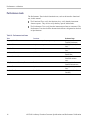
Finding other information
This manual focuses on the performance verification of the arbitrary function
generator. See the following list for other documents supporting the instrument.
All documents except the Online Help are on the AFG2021 Arbitrary Function
G
enerator Documentation CD-ROM that ship with instrument.
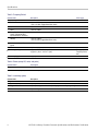
Document Description
AFG2021 Quick Start U ser Manual A quick reference to major features of the instrument and how they operate. It also provides
several tutorials to familiarize you w ith basic instrument features.
AFG2021 Programmer Manual An encyclopedia of topics that describe the arbitrary function generator interface and features,
and gives background information on how to use them. It provides Menu Structures, User
Interface, and Programming Information.
AFG2021 Online Help A online help system, integrated with the U ser Interface application that ships with this
product. The help is preinstalled in the instrument.
AFG2021 Arbitrary Function Generator Specifi cations and Performance Verification 3

Preface
Manual conventions
This manual uses certain conventions that you should become familiar with.
Modules
Throughout t
his manual, any replaceable component, assembly, or part of the
arbitrary function gen erator is referred to generically as a module. In general, a
module is an assembly (such as a circuit board). Sometimes a single component is
a module; for example, the chassis of the arbitrary function generator is a module.
Safety
Symbols and terms r elated to safety appear in the Safety Summary near the
beginning of this manual.
4 AFG2021 Arbitrary Function Generator Specifications and Performance Verification

Specifications
These specifications apply to the AFG2021 Arbitrary Function Generator. All
specifications are guaranteed unless labeled “typical”. Typical specifications are
provided for
your convenience but are not guaranteed.
Specifications that are check marked with the
symbol are checked directly (or
indirectly
) in the Performance Verification section.
All specifications apply to the arbitrary function generator unless noted o therwise.
These spec
ifications are v alid under the following conditions:
The instrument must have been calibrated/adjusted at an ambient temperatur e
between +
20 °C and +30 °C.
The instrument must be operating at an ambient temperature between 0 °C
and +50 °
C.
The instrument must have had a warm-up period of at least 20 minutes.
The instrument must b e in an environment with temperature, altitude, and
humidity within the operating limits described in these specifications.
Electrical specifications
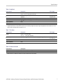
Table 1: Operating mode
Characteristic Description
Run m ode
Continuous, Modulation, Sweep, and Burst
Burst count
1 to 1,000,000 cycles or infinite
Internal trigger rate 1.000 μs to 500.0 s
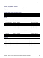
Table 2: Waveforms
Characteristic Description
Standard Sine, Square, Pulse, Ramp, More (Sin(x)/x, Noise, DC, Gaussian, Lorentz, Exponential Rise,
E
xponential Decay, and Haversine)
Arbitrary waveform
Waveform length
2 to 131,072
Sampling rate 250 MS/s
Resolution 14 bits
Number of non-volatile
waveform memories
4
AFG2021 Arbitrary Function Generator Specifi cations and Performance Verification 5

Specifications
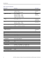
Table 3: Freque
ncy/Period
Characteristic Description PV ref page
Frequency ran
ge
Sine
1 μHz to 20 MHz
1 μHz to 10 MHz
(Trigger/Gated Burst mode)
Square
1 μHz to 10 MHz
Pulse 1 mHz to 10 MHz
Ramp, Sin(x)/X, Gaussian,
Lorentz, E
xponential Rise,
Exponential Decay, Haversine
1 μHz to 200 kHz
Arbitrary 1 mHz to 10 M
Hz
1 mHz to 5 MHz (Trigger/Gated Burst mode)
Noise bandwidth (-3 dB),
typical
20 MHz
Resolution 1 μHz or 12 digits
Accuracy (stability)
±1 ppm, 0 °C to 50 °C (except Arb)
±1 ppm ±1 μHz, 0 °C to 50 °C (Arb)
(See page 22,
Frequency/Period
test.)
Accuracy (aging)
±1 ppm/
year
Table 4: Phase (except DC, noise, and pulse)
Chara
cteristics
Description
Range
1
–360.
00° to +360.00°
1
Resolution: 0.01° (sine), 0.1° (other standard waveforms)
Table 5: Lead d elay (pulse)
Char
acteristic
Desc
ription
Range
Continuous mode
0 ps to period
Triggered/Gated Burst mode 0 ps to period – [pulse width + 0.8 * (leading edge time + trailing edge time)]
Resolution 10 ps or 8 digits
6 AFG2021 Arbitrary Function Generator Specifications and Performance Verification

Specifications
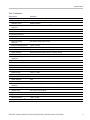
Table 6: Amplit
ude
Characteristic Description PV ref page
Range 10 mV
p-p
to 10 V
p-p
20 mV
p-p
to 20 V
p-p
(into open circuit load)
Accuracy
±(1% of setting +1 mV) (at 1 kHz sine waveform), 0 V offset, >10 mV
p-p
amplitude
(See page 23,
Amplitude test.)
Resolution 0.1 m V
p-p
,0.1mV
rms
, 1 mV, 0.1 dBm or 4 digits
Units
1
V
p-p
,V
rms
, dBm, and Volt (High level and Low level)
Output impedance 50 Ω
Isolation
2
<42V
pk
max
imum to earth
1
dBm is used only for sine waveform. V
rms
is not available for Arb and Noise waveforms.
2
To prevent electrical shock, use this product so that the sum of the floating voltage and the output voltage of t he generator does not exceed 42 V
pk
. Do not
touch the center of the BNC while the equipment is in use.
Table 7: D
Coffset
Characteristic Description PV ref page
Range
±5 V
pk ac + dc
into 50 Ω load
±10 V
pk ac + dc
into open circuit load
Accuracy
1
±(1% of |setting| +5 mV + 0.5% of amplitude (V
p-p
)) (|setting| ≤ 5 V) (See page 25,
DC offs
et test.)
Resolution 1 mV
Output impedance 50 Ω
1
Add 0.5 mV per °C for operation outside the range of 20 °C to 30 °C.
Table 8: Internal noise add
Characteristic Description
Range
0% to 50% of amplitude setting
Resolution
1%
1
When Noise Add In is selected, the amplitude of the signal will become half of the amplitude.
AFG2021 Arbitrary Function Generator Specifi cations and Performance Verification 7

Specifications
Table 9: Output
characteristics
Characteristic Description PV ref page
Sine wave
Flatness
(at 1.0 V
p-p
amplitude (+4 dBm), relative to 100 kHz)
<5MHz: ±0.15dB
5MHz≤ frq ≤ 2
0MHz:±0.3dB
(See page 26,
AC flatness
test.)
Harmonic distortion
(at 1.0 V
p-p
amplitude)
10 Hz ≤ frq < 20 kHz: < –70 dBc
20 kHz ≤ frq < 1 M Hz: < –60 dBc
1MHz≤ frq ≤
10 MHz: < –50 dBc
10 MHz ≤ frq ≤ 20 MHz: < –40 dBc
(See page 28,
Harmonics
distortion test.)
Total harmonic distortion
(THD)
(at 1 V
p-p
amplitude)
10 Hz to 20 kHz: < 0.2%
(See page 29,
Total harmonic
distorti
on test.)
Spurious (nonharmonic)
(at 1 V
p-p
amplitude)
10 Hz ≤ frq < 1 MHz: < –60 dBc
1MHz≤ frq ≤ 20 MHz: < –50 dBc
(See pag
e 32,
Spurious test.)
Phase noise, typical
(at 1 V
p-p
amplitude)
20 MHz:
< –110 dBc/Hz at 10 kHz offset
Residual clock noise, typical –63 dBm
Square wave
Rise time/fall time
≤ 18 ns
(See page 34,
Rise
-Fall time
test.)
Jitter (rms), typical
500 p
s
Pul
se
Pulse width 30 ns to 999.99 s
Resolution 10 ps or 5 digits
Pu
lse duty
0.001% to 99.999%
Leading edge/trailing edge
transition time
(at 10% to 90% of amplitude)
18 ns to 0.625 * pulse period
Resolution 10 ps or 4 digits
Overshoot, typical < 5%
Jitter (rms), typical
500 ps
Ramp
Linearity, typical
(at frequency: 1 kHz, amplitude: 1 V
p-p
, symmetry: 100%)
≤ 0.1% of peak output at 10% to 90% of amplitude range
Symmetry 0% to 100%
Arbitrary
Rise time/fall time, typical
≤ 20 ns
Jitter (rms), typical
4ns
8 AFG2021 Arbitrary Function Generator Specifications and Performance Verification

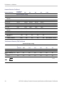
Specifications
Table 10: Modul
ation
Characteristic Description
AM (Amplitude Modulation)
Carrier waveforms Standard waveforms (except Pulse, DC, and Noise) and Arb
Modulation
source
Internal or
External
Internal modulating
waveforms
Sine, Squar
e, Ramp, Noise, and Arb
1
Internal m
odulating frequency
2mHzto50.0kHz
Depth
0.0% to 120
.0%
FM (Frequ
ency Modulation)
Carrier
waveforms
Standar
d waveforms (except Pulse, DC, and Noise) and Arb
Modulation source Internal or External
Internal modulating
waveforms
Sine, Square, Ramp, Noise, and Arb
2
Internal modulating frequency
2mHzto50.0kHz
Peak deviation
DC to 10 MHz
PM (Phase Modulation)
Carrier waveforms Standard waveforms (except Pulse, DC, and Noise) and Arb
Modulation source Internal or External
Int
ernal modulating
waveforms
Sine, Square, Ramp, Noise, and Arb
2
Internal modulating frequency
2mH
z to 50.0 kHz
Ph
ase deviation range
0.
0 to 180.0 degrees
FS
K (Frequency Shift Keying)
C
arrier waveforms
S
tandard waveforms (except Pulse, DC, and Noise) and Arb
Modulation source Internal or External
Internal key rate 2 mHz to 1.0 MHz
Number of keys
2
PWM (Pulse Width Modulation)
Carrier waveforms
Pulse
Modulation source Internal or External
Internal modulating
waveforms
Sine, Square, Ramp, Noise, and Arb
2
Internal modulating frequency
2mHzto50.0kHz
Deviation range
0.0% to 50.0% of pulse period
Sweep
Type Linear or Logarithmic
Start/stop frequency
3
1 μHz to 20 MHz
Sweep/hold/return time
4
AFG2021 Arbitrary Function Generator Specifi cations and Performance Verification 9

Specifications
Table 10: Modulation (cont.)
Characteristic Description
Range
1 ms to 300 s (sweep time)
0 ms to 300 s (hold/return time)
Resolution 1 ms or 4 digits
Total sweep time accuracy,
typical
≤ 0.4%
1
The maximum waveform length for Arb is 4,096. Waveform data points over 4,096 are ignored.
2
The maximum waveform length for Arb is 2,048. Waveform data points over 2,048 are ignored.
3
Pulse, DC, and Noise waveforms are not available. Start and stop frequencies depend on the waveform shape.
4
Total sweep time = Sweep tim e + Hold time + Return time ≤ 300 s
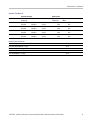
Input and output specifications
Table 11: Front panel
Characteristic Description
Trigger output
Level
Positive TTL level pulse into 1 kΩ
Impedance
50 Ω
Jitter (rms), typic al
500 ps
Trigger input
Level TTL compatible
Pulse width 100 ns minimum
Impedance
10 kΩ
Slope Positive/negative selectable
Trigger delay 0.0 ns to 85.0 s
Resolution 100 ps or 5 digits
Jitter (rms), typical <500 ps (Trigger input to Signal output at Burst mode)
10 AFG2021 Arbitrary Function Generator Specifications and Performance Verification
Page is loading ...
Page is loading ...
Page is loading ...
Page is loading ...
Page is loading ...
Page is loading ...
Page is loading ...
Page is loading ...
Page is loading ...
Page is loading ...
Page is loading ...
Page is loading ...
Page is loading ...
Page is loading ...
Page is loading ...
Page is loading ...
Page is loading ...
Page is loading ...
Page is loading ...
Page is loading ...
Page is loading ...
Page is loading ...
Page is loading ...
Page is loading ...
Page is loading ...
-
 1
1
-
 2
2
-
 3
3
-
 4
4
-
 5
5
-
 6
6
-
 7
7
-
 8
8
-
 9
9
-
 10
10
-
 11
11
-
 12
12
-
 13
13
-
 14
14
-
 15
15
-
 16
16
-
 17
17
-
 18
18
-
 19
19
-
 20
20
-
 21
21
-
 22
22
-
 23
23
-
 24
24
-
 25
25
-
 26
26
-
 27
27
-
 28
28
-
 29
29
-
 30
30
-
 31
31
-
 32
32
-
 33
33
-
 34
34
-
 35
35
-
 36
36
-
 37
37
-
 38
38
-
 39
39
-
 40
40
-
 41
41
-
 42
42
-
 43
43
-
 44
44
-
 45
45


Ask a question and I''ll find the answer in the document
Finding information in a document is now easier with AI
Related papers
-
Tektronix AFG2021 User manual
-
-
Tektronix AWG4162 Technical Reference
-
-
-
Tektronix AFG3022 User manual
-
Tektronix AFG3252 User manual
-
-
Tektronix PSM4120 User manual
-