ASROCK 970 Extreme3 R2.0 Quick Installation Manual
- Type
- Quick Installation Manual

1
ASRock 970 Extreme3 R2.0 Motherboard
English
Copyright Notice:
No part of this installation guide may be reproduced, transcribed, transmitted, or trans-
lated in any language, in any form or by any means, except duplication of documentation
by the purchaser for backup purpose, without written consent of ASRock Inc.
Products and corporate names appearing in this guide may or may not be registered
trademarks or copyrights of their respective companies, and are used only for identica-
tion or explanation and to the owners’ benet, without intent to infringe.
Disclaimer:
Specications and information contained in this guide are furnished for informational use
only and subject to change without notice, and should not be constructed as a commit-
ment by ASRock. ASRock assumes no responsibility for any errors or omissions that may
appear in this guide.
With respect to the contents of this guide, ASRock does not provide warranty of any kind,
either expressed or implied, including but not limited to the implied warranties or condi-
tions of merchantability or tness for a particular purpose. In no event shall ASRock, its
directors, ofcers, employees, or agents be liable for any indirect, special, incidental, or
consequential damages (including damages for loss of prots, loss of business, loss of
data, interruption of business and the like), even if ASRock has been advised of the pos-
sibility of such damages arising from any defect or error in the guide or product.
This device complies with Part 15 of the FCC Rules. Operation is subject to the following
two conditions:
(1) this device may not cause harmful interference, and
(2) this device must accept any interference received, including interference that
may cause undesired operation.
CALIFORNIA, USA ONLY
The Lithium battery adopted on this motherboard contains Perchlorate, a toxic substance
controlled in Perchlorate Best Management Practices (BMP) regulations passed by the
California Legislature. When you discard the Lithium battery in California, USA, please
follow the related regulations in advance.
“Perchlorate Material-special handling may apply, see
www.dtsc.ca.gov/hazardouswaste/perchlorate”
ASRock Website: http://www.asrock.com
Published October 2012
Copyright
©
2012 ASRock INC. All rights reserved.

2
ASRock 970 Extreme3 R2.0 Motherboard
English
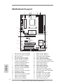
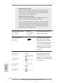
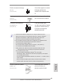
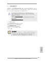
Motherboard Layout
1 ATX 12V Power Connector (ATX12V1) 19 SATA3 Connector (SATA3_4)
2 Chassis Fan Connector (CHA_FAN3) 20 SATA3 Connector (SATA3_5)
3 AM3+ CPU Socket 21 Clear CMOS Jumper (CLRCMOS1)
4 CPU Heatsink Retention Module 22 Power LED Header (PLED1)
5 CPU Fan Connector (CPU_FAN2) 23 System Panel Header (PANEL1)
6 CPU Fan Connector (CPU_FAN1) 24 Chassis Speaker Header (SPEAKER1)
7 2 x 240-pin DDR3 DIMM Slots 25 Consumer Infrared Module Header (CIR1)
(Dual Channel: DDR3_A1, DDR3_B1) 26 USB 2.0 Header (USB_4_5)
8 2 x 240-pin DDR3 DIMM Slots 27 USB 2.0 Header (USB_6_7)
(Dual Channel: DDR3_A2, DDR3_B2) 28 USB 2.0 Header (USB_8_9)
9 ATX Power Connector (ATXPWR1) 29 Infrared Module Header (IR1)
10 Power Fan Connector (PWR_FAN1) 30 COM Port Header (COM1)
11 Northbridge Controller 31 HDMI_SPDIF Header (HDMI_SPDIF1)
12 Chassis Fan Connector (CHA_FAN1) 32 Front Panel Audio Header (HD_AUDIO1)
13 Southbridge Controller 33 PCI Slots (PCI1-2)
14 SPI Flash Memory (32Mb) 34 PCI Express 2.0 x16 Slot (PCIE4)
15 Chassis Fan Connector (CHA_FAN2) 35 PCI Express 2.0 x1 Slot (PCIE3)
16 SATA3 Connector (SATA3_3) 36 PCI Express 2.0 x16 Slot (PCIE2)
17 SATA3 Connector (SATA3_1) 37 PCI Express 2.0 x1 Slot (PCIE1)
18 SATA3 Connector (SATA3_2) 38 USB 3.0 Header (USB3_2_3)
FSB800
DDR3_A1 (64 bit, 240-pin modu le)
DDR3_A2 (64 bit, 240-pin module)
FSB800
DDR3_B1 (64 bit, 240-pin modu le)
DDR3_B2 (64 bit, 240-pin module)
AMD
SB950
Chipset
HD_ AUDI O1
1
HDLE D RESE T
PLED PW RBTN
1
PANEL 1
SPE AKER 1
1
AMD
970
Chipset
USB _4_5
1
PS2
Keyboard
RJ-45 LA N
eSATA3
USB 2. 0
T: US B2
B: USB 3
USB 2. 0
T: USB0
B: USB1
Coaxial
SPDIF
Optical
SPDIF
USB 3.0
T: U SB0
B: USB1
Top:
SID E SP K
Cen ter :
REA R SP K
Bot tom :
CTR BA SS
Top:
LIN E IN
Cen ter :
FRO NT
Bot tom :
MIC IN
SOC KET AM3 b
PS2
Mouse
CIR1
1
USB _6_7
1
COM 1
1
IR1
1
HDMI _SPDIF 1
PCIE2
PCIE1
PCI1
CM OS
BA TT ER Y
AUD IO
COD EC
ATX1 2V1
CPU _FAN2
CHA _FAN3
CPU _FAN 1
LAN
PHY
1
PLE D1
CLR CMOS 1
1
Fr ont USB 3.0
140W CPU
D DR3 2100+
AM3+
RoHS
970 Extreme3
ErP/EuP Ready
Su pport 8-Core CPU
32Mb
BIOS
Supe r
I/O
1
2
3
4
5
6
7
8
9
10
11
12
13
14
15
16
17
18
1920
21
23
24
25
26
27
28
29
30
31
32
33
34
35
36
37
22
X
Fast US B
PCIE3
PCIE4
PCI2
SATA3 _1
SATA3 _3
SATA3 _2
SATA3 _4SATA3 _5
USB _8_9
1
1
X
Fast LA N
PWR _FAN1
CHA _FAN2
CHA _FAN 1
X
Fast RA M
USB 3_2 _3
38

3
ASRock 970 Extreme3 R2.0 Motherboard
English
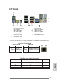
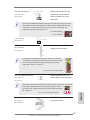
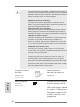
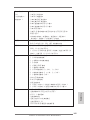
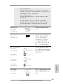
I/O Panel
**
If you use 2-channel speaker, please connect the speaker’s plug into “Front Speaker Jack”.
See the table below for connection details in accordance with the type of speaker you use.
TABLE for Audio Output Connection
Audio Output Channels Front Speaker Rear Speaker Central / Bass Side Speaker
(No. 8) (No. 5) (No. 6) (No. 4)
2 V -- -- --
4 V V -- --
6 V V V --
8 V V V V
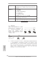
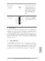
LAN Port
ACT/LINK
LED
SPEED
LED
* There are two LED next to the LAN port. Please refer to the table below for the LAN port LED
indications.
LAN Port LED Indications
Activity/Link LED SPEED LED
Status Description Status Description
Off No Link Off 10Mbps connection
Blinking Data Activity Orange 100Mbps connection
On Link Green 1Gbps connection
1 PS/2 Mouse Port (Green) 9 Microphone (Pink)
* 2 LAN RJ-45 Port 10 USB 3.0 Port (USB01)
3 USB 2.0 Ports (USB23) *** 11 eSATA3 Connector
4 Side Speaker (Gray) 12 USB 2.0 Ports (USB01)
5 Rear Speaker (Black) 13 Optical SPDIF Out Port
6 Central / Bass (Orange) 14 Coaxial SPDIF Out Port
7 Line In (Light Blue) 15 PS/2 Keyboard Port (Purple)
** 8 Front Speaker (Lime)

4
ASRock 970 Extreme3 R2.0 Motherboard
English
To enable Multi-Streaming function, you need to connect a front panel audio cable to the front
panel audio header. After restarting your computer, you will nd “Mixer” tool on your system.
Please select “Mixer ToolBox” , click “Enable playback multi-streaming”, and click “ok”.
Choose “2CH”, “4CH”, “6CH”, or “8CH” and then you are allowed to select “Realtek HDA Pri-
mary output” to use Rear Speaker, Central/Bass, and Front Speaker, or select “Realtek HDA
Audio 2nd output” to use front panel audio.
*** eSATA3 connector supports SATA Gen3 in cable 1M.

5
ASRock 970 Extreme3 R2.0 Motherboard
English
1. Introduction
Thank you for purchasing ASRock 970 Extreme3 R2.0 motherboard, a reliable
motherboard produced under ASRock’s consistently stringent quality control. It
delivers excellent performance with robust design conforming to ASRock’s commit-
ment to quality and endurance.
This Quick Installation Guide contains introduction of the motherboard and step-by-
step installation guide. More detailed information of the motherboard can be found
in the user manual presented in the Support CD.
Because the motherboard specications and the BIOS software might
be updated, the content of this manual will be subject to change without
notice. In case any modications of this manual occur, the updated ver-
sion will be available on ASRock website without further notice. You may
nd the latest VGA cards and CPU support lists on ASRock website as
well. ASRock website http://www.asrock.com
If you require technical support related to this motherboard, please visit
our website for specic information about the model you are using.
www.asrock.com/support/index.asp
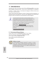
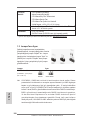
1.1 Package Contents
ASRock 970 Extreme3 R2.0 Motherboard (ATX Form Factor)
ASRock 970 Extreme3 R2.0 Quick Installation Guide
ASRock 970 Extreme3 R2.0 Support CD
2 x Serial ATA (SATA) Data Cables (Optional)
1 x I/O Panel Shield
ASRock Reminds You...
To get better performance in Windows
®
8 / 8 64-bit / 7 / 7 64-bit / Vista
TM
/ Vista
TM
64-bit, it is recommended to set the BIOS option in Storage
Conguration to AHCI mode. For the BIOS setup, please refer to the “User
Manual” in our support CD for details.

6
ASRock 970 Extreme3 R2.0 Motherboard
English
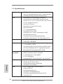
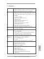
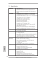
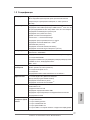
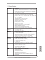
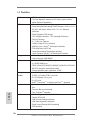
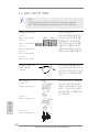
1.2 Specications
Platform - ATX Form Factor
- ASRock DuraCap (2.5 x longer life time) (100%
Japan-made high-quality Conductive Polymer Capacitors)
CPU - Support for Socket AM3+ processors
- Support for Socket AM3 processors: AMD Phenom
TM
II X6 /
X4 / X3 / X2 (except 920 / 940) / Athlon II X4 / X3 / X2 /
Sempron processors
- Supports 8-Core CPU
- Supports UCC feature (Unlock CPU Core) (see CAUTION 1)
- Digi Power Design
- 4 + 1 Power Phase Design
- Supports CPU up to 140W
- Supports AMD’s Cool ‘n’ Quiet
TM
Technology
- FSB 2400 MHz (4.8 GT/s)
- Supports Untied Overclocking Technology
- Supports Hyper-Transport 3.0 (HT 3.0) Technology
Chipset - Northbridge: AMD 970
- Southbridge: AMD SB950
Memory - Dual Channel DDR3 Memory Technology
- 4 x DDR3 DIMM slots
- Support DDR3 2100+(OC)/1866(OC)/1800(OC)/1600(OC)/
1333/1066/800 non-ECC, un-buffered memory
(see CAUTION 2)
- Max. capacity of system memory: 32GB (see CAUTION 3)
Expansion Slot - 2 x PCI Express 2.0 x16 slots
(PCIE2 @ x16 mode; PCIE4 @ x4 mode)
- 2 x PCI Express 2.0 x1 slots
- 2 x PCI slots
- Supports AMD
TM
Quad CrossFireX
TM
and CrossFireX
TM
Audio - 7.1 CH HD Audio with Content Protection
(Realtek ALC892 Audio Codec)
- Premium Blu-ray audio support
- Supports THX TruStudio
TM
LAN - PCIE x1 Gigabit LAN 10/100/1000 Mb/s
- Realtek RTL8111E
- Supports Wake-On-LAN
- Supports LAN Cable Detection
- Supports Energy Efcient Ethernet 802.3az
- Supports PXE

7
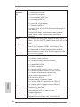
ASRock 970 Extreme3 R2.0 Motherboard
English
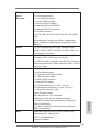
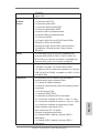
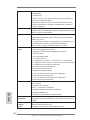
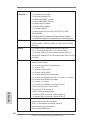
Rear Panel I/O I/O Panel
- 1 x PS/2 Mouse Port
- 1 x PS/2 Keyboard Port
- 1 x Coaxial SPDIF Out Port
- 1 x Optical SPDIF Out Port
- 4 x Ready-to-Use USB 2.0 Ports
- 2 x Ready-to-Use USB 3.0 Ports
- 1 x eSATA3 Connector
- 1 x RJ-45 LAN Port with LED (ACT/LINK LED and SPEED
LED)
- HD Audio Jack: Side Speaker/Rear Speaker/Central/Bass/
Line in/Front Speaker/Microphone
SATA3 - 5 x SATA3 6.0 Gb/s connectors, support RAID (RAID 0,
RAID 1, RAID 5 and RAID 10), NCQ, AHCI and "Hot Plug"
functions
USB 3.0 - 2 x Rear USB 3.0 ports by Etron EJ188H, support USB
1.1/2.0/3.0 up to 5Gb/s
- 1 x Front USB 3.0 header (supports 2 USB 3.0 ports) by
Etron EJ188H, supports USB 1.1/2.0/3.0 up to 5Gb/s
Connector - 5 x SATA3 6.0Gb/s connectors
- 1 x IR header
- 1 x CIR header
- 1 x COM port header
- 1 x HDMI_SPDIF header
- 1 x Power LED header
- 2 x CPU Fan connectors (1 x 4-pin, 1 x 3-pin)
- 3 x Chassis Fan connectors (1 x 4-pin, 2 x 3-pin)
- 1 x Power Fan connector (3-pin)
- 24 pin ATX power connector
- 8 pin 12V power connector
- Front panel audio connector
- 3 x USB 2.0 headers (support 6 USB 2.0 ports)
- 1 x USB 3.0 header (supports 2 USB 3.0 ports)
BIOS Feature - 32Mb AMI UEFI Legal BIOS with GUI support
- Supports “Plug and Play”
- ACPI 1.1 Compliance Wake Up Events
- Supports jumperfree
- SMBIOS 2.3.1 Support
- CPU, VCCM, NB, SB Voltage Multi-adjustment

8
ASRock 970 Extreme3 R2.0 Motherboard
English
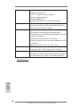
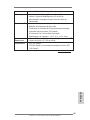
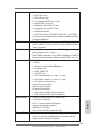
Support CD - Drivers, Utilities, AntiVirus Software (Trial Version),
CyberLink MediaEspresso 6.5 Trial, Google Chrome
Browser and Toolbar
Hardware - CPU Temperature Sensing
Monitor - Chassis Temperature Sensing
- CPU/Chassis/Power Fan Tachometer
- CPU/Chassis Quiet Fan
- CPU/Chassis Fan Multi-Speed Control
- Voltage Monitoring: +12V, +5V, +3.3V, Vcore
OS - Microsoft
®
Windows
®
8 / 8 64-bit / 7 / 7 64-bit / Vista
TM
/
Vista
TM
64-bit / XP / XP 64-bit compliant (see CAUTION 4)
Certications - FCC, CE, WHQL
- ErP/EuP Ready (ErP/EuP ready power supply is required)
* For detailed product information, please visit our website: http://www.asrock.com
WARNING
Please realize that there is a certain risk involved with overclocking,
including adjusting the setting in the BIOS, applying Untied Overclocking
Technology, or using third-party overclocking tools. Overclocking may
affect your system’s stability, or even cause damage to the components
and devices of your system. It should be done at your own risk and
expense. We are not responsible for possible damage caused by
overclocking.

9
ASRock 970 Extreme3 R2.0 Motherboard
English
CAUTION!
1. ASRock UCC (Unlock CPU Core) feature simplies AMD CPU
activation. As long as a simple switch of the UEFI option “AS-
Rock UCC”, you can unlock the extra CPU core to enjoy an
instant performance boost. When UCC feature is enabled, the
dual-core or triple-core CPU will boost to the quad-core CPU,
and some CPU, including quad-core CPU, can also increase L3
cache size up to 6MB, which means you can enjoy the upgrade
CPU performance with a better price. Please be noted that UCC
feature is supported with AM3/AM3+ CPU only, and in addition,
not every AM3/AM3+ CPU can support this function because
some CPU’s hidden core may be malfunctioned.
2. Whether 2100/1866/1800/1600MHz memory speed is sup-
ported depends on the AM3/AM3+ CPU you adopt. If you want
to adopt DDR3 2100/1866/1800/1600 memory module on this
motherboard, please refer to the memory support list on our
website for the compatible memory modules. Non OC mode’s
DDR3 1866 is supported by AM3+ CPU.
ASRock website: http://www.asrock.com
3. Due to the operating system limitation, the actual memory size
may be less than 4GB for the reservation for system usage un-
der Windows
®
8 / 7 / Vista
TM
/ XP. For Windows
®
64-bit OS with
64-bit CPU, there is no such limitation.
4. ASRock XFast RAM is not supported by Microsoft
®
Windows
®
XP / XP 64-bit.

10
ASRock 970 Extreme3 R2.0 Motherboard
English
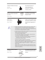
1.3 Unique Features
ASRock Extreme Tuning Utility (AXTU)
ASRock Extreme Tuning Utility (AXTU) is an all-in-one tool to
ne-tune different system functions in a user-friendly interface,
which includes Hardware Monitor, Fan Control, Overclocking,
OC DNA, IES and XFast RAM. In Hardware Monitor, it shows
the major readings of your system. In Fan Control, it shows the
fan speed and temperature for you to adjust. In Overclocking,
you are allowed to overclock CPU frequency for optimal system
performance. In OC DNA, you can save your OC settings as
a prole and share it with your friends. Your friends then can
load the OC prole to their own system to get the same OC set-
tings. In IES (Intelligent Energy Saver), the voltage regulator
can reduce the number of output phases to improve efciency
when the CPU cores are idle without sacricing computing per-
formance. In XFast RAM, it fully utilizes the memory space that
cannot be used under Windows
®
OS 32-bit CPU.
ASRock Instant Boot
ASRock Instant Boot allows you to turn on your PC in just a few
seconds, provides a much more efcient way to save energy,
time, money, and improves system running speed for your sys-
tem. It leverages the S3 and S4 ACPI features which normally
enable the Sleep/Standby and Hibernation modes in Windows
®
to shorten boot up time. By calling S3 and S4 at specic timing
during the shutdown and startup process, Instant Boot allows
you to enter your Windows
®
desktop in a few seconds.
ASRock Instant Flash
ASRock Instant Flash is a BIOS ash utility embedded in Flash
ROM. This convenient BIOS update tool allows you to update
system BIOS without entering operating systems rst like MS-
DOS or Windows
®
. With this utility, you can press the <F6> key
during the POST or the <F2> key to enter into the BIOS setup
menu to access ASRock Instant Flash. Just launch this tool and
save the new BIOS le to your USB ash drive, oppy disk or
hard drive, then you can update your BIOS only in a few clicks
without preparing an additional oppy diskette or other compli-
cated ash utility. Please be noted that the USB ash drive or
hard drive must use FAT32/16/12 le system.

11
ASRock 970 Extreme3 R2.0 Motherboard
English
ASRock APP Charger
If you desire a faster, less restricted way of charging your
Apple devices, such as iPhone/iPad/iPod Touch, ASRock has
prepared a wonderful solution for you - ASRock APP Charger.
Simply install the APP Charger driver, it makes your iPhone
charge much quickly from your computer and up to 40% faster
than before. ASRock APP Charger allows you to quickly charge
many Apple devices simultaneously and even supports continu-
ous charging when your PC enters into Standby mode (S1),
Suspend to RAM (S3), hibernation mode (S4) or power off (S5).
With APP Charger driver installed, you can easily enjoy the mar-
velous charging experience.
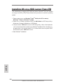
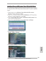
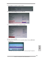
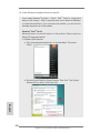
ASRock XFast USB
ASRock XFast USB can boost USB storage device perfor-
mance. The performance may depend on the properties of the
device.
ASRock XFast LAN
ASRock XFast LAN provides a faster internet access, which in-
cludes the benets listed below. LAN Application Prioritization:
You can congure your application’s priority ideally and/or add
new programs. Lower Latency in Game: After setting online
game’s priority higher, it can lower the latency in games. Trafc
Shaping: You can watch Youtube HD videos and download si-
multaneously. Real-Time Analysis of Your Data: With the status
window, you can easily recognize which data streams you are
transferring currently.
ASRock XFast RAM
ASRock XFast RAM is a new function that is included into AS-
Rock Extreme Tuning Utility (AXTU). It fully utilizes the memory
space that cannot be used under Windows
®
OS 32-bit CPU.
ASRock XFast RAM shortens the loading time of previously
visited websites, making web surfing faster than ever. And it
also boosts the speed of Adobe Photoshop 5 times faster. An-
other advantage of ASRock XFast RAM is that it reduces the
frequency of accessing your SSDs or HDDs in order to extend
their lifespan.

12
ASRock 970 Extreme3 R2.0 Motherboard
English
ASRock Crashless BIOS
ASRock Crashless BIOS allows users to update their BIOS
without fear of failing. If power loss occurs during the BIOS up-
date process, ASRock Crashless BIOS will automatically nish
the BIOS update procedure after regaining power. Please note
that BIOS les need to be placed in the root directory of your
USB disk. Only USB2.0 ports support this feature.
ASRock OMG (Online Management Guard)
Administrators are able to establish an internet curfew or restrict
internet access at specied times via OMG. You may schedule
the starting and ending hours of internet access granted to other
users. In order to prevent users from bypassing OMG, guest
accounts without permission to modify the system time are re-
quired.
ASRock Internet Flash
ASRock Internet Flash searches for available UEFI firmware
updates from our servers. In other words, the system can auto-
detect the latest UEFI from our servers and ash them without
entering Windows
®
OS. Please note that you must be running
on a DHCP congured computer in order to enable this function.
ASRock On/Off Play Technology
ASRock On/Off Play Technology allows users to enjoy the great
audio experience from the portable audio devices, such like
MP3 player or mobile phone to your PC, even when the PC is
turned off (or in ACPI S5 mode)! This motherboard also provides
a free 3.5mm audio cable (optional) that ensures users the most
convenient computing environment.
ASRock UEFI System Browser
ASRock UEFI system browser is a useful tool included in
graphical UEFI. It can detect the devices and configurations
that users are currently using in their PC. With the UEFI system
browser, you can easily examine the current system congura-
tion in UEFI setup.
ASRock Dehumidier Function
Users may prevent motherboard damages due to dampness by
enabling “Dehumidier Function”. When enabling Dehumidier

13
ASRock 970 Extreme3 R2.0 Motherboard
English
Function, the computer will power on automatically to dehumidi-
fy the system after entering S4/S5 state.
ASRock Fast Boot
With ASRock’s exclusive Fast Boot technology, it takes less
than 1.5 seconds to logon to Windows
®
8 from a cold boot. No
more waiting! The speedy boot will completely change your user
experience and behavior.
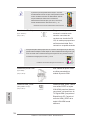
ASRock X-Boost
ASRock’s X-Boost Technology is a smart auto-overclocking
function and is brilliantly designed to unlock the hidden power of
your CPUs. Simply press “X” when turning on the PC, X-Boost
will automatically overclock the relative components to get up to
15.77% performance boost! With the smart X-Boost, overclock-
ing CPU can become a near one-button process.
* The functionality of “Unlock CPU Cores” feature might vary by
different processors.
ASRock Restart to UEFI
Windows
®
8 brings the ultimate boot up experience. The light-
ning boot up speed makes it hard to access the UEFI setup. AS-
Rock Restart to UEFI technology is designed for those requiring
frequent UEFI access. It allows users to easily enter the UEFI
automatically when turning on the PC next time. Just simply
enable this function; the PC will be assured to access the UEFI
directly in the very beginning.
ASRock Good Night LED
ASRock Good Night LED technology can offer you a better en-
vironment by extinguishing the unessential LED. By enabling
Good Night LED in BIOS, the Power / HDD / LAN LED will be
switched off when system is on. Not only this, Good night LED
will automatically switch off Power and Keyboard LED when the
system enters into Standby / Hibernation mode as well.

14
ASRock 970 Extreme3 R2.0 Motherboard
English
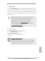
2. Installation
This is an ATX form factor motherboard. Before you install the motherboard, study
the conguration of your chassis to ensure that the motherboard ts into it.
Pre-installation Precautions
Take note of the following precautions before you install motherboard
components or change any motherboard settings.
Before you install or remove any component, ensure that the
power is switched off or the power cord is detached from the
power supply. Failure to do so may cause severe damage to the
motherboard, peripherals, and/or components.
1. Unplug the power cord from the wall socket before touching any
component.
2. To avoid damaging the motherboard components due to static elec-
tricity, NEVER place your motherboard directly on the carpet or the
like. Also remember to use a grounded wrist strap or touch a safety
grounded object before you handle components.
3. Hold components by the edges and do not touch the ICs.
4. Whenever you uninstall any component, place it on a grounded anti-
static pad or in the bag that comes with the component.
5. When placing screws into the screw holes to secure the mother-
board to the chassis, please do not over-tighten the screws! Doing
so may damage the motherboard.

15
ASRock 970 Extreme3 R2.0 Motherboard
English
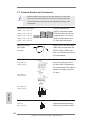
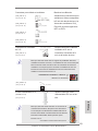
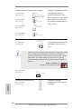
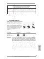
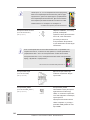
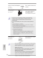
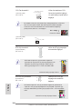
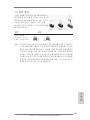
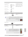
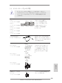
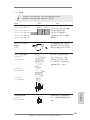
STEP 1:
Lift Up The Socket Lever
STEP 2 / STEP 3:
Match The CPU Golden Triangle
To The Socket Corner Small
Triangle
STEP 4:
Push Down And Lock
The Socket Lever
Lever 90° Up
CPU Golden Triangle
Socker Corner
Small Triangle
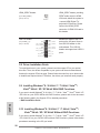
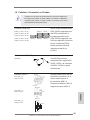
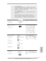
2.1 CPU Installation
Step 1. Unlock the socket by lifting the lever up to a 90
o
angle.
Step 2. Position the CPU directly above the socket such that the CPU corner with
the golden triangle matches the socket corner with a small triangle.
Step 3. Carefully insert the CPU into the socket until it ts in place.
The CPU ts only in one correct orientation. DO NOT force the CPU
into the socket to avoid bending of the pins.
Step 4. When the CPU is in place, press it rmly on the socket while you push
down the socket lever to secure the CPU. The lever clicks on the side tab
to indicate that it is locked.
2.2 Installation of CPU Fan and Heatsink
After you install the CPU into this motherboard, it is necessary to install a
larger heatsink and cooling fan to dissipate heat. You also need to spray
thermal grease between the CPU and the heatsink to improve heat dis-
sipation. Make sure that the CPU and the heatsink are securely fastened
and in good contact with each other. Then connect the CPU fan to the
CPU FAN connector (CPU_FAN1, see Page 2, No. 6 or CPU_FAN2, see
Page 2, No. 5). For proper installation, please kindly refer to the instruc-
tion manuals of the CPU fan and the heatsink.

16
ASRock 970 Extreme3 R2.0 Motherboard
English
2.3 Installation of Memory Modules (DIMM)
This motherboard provides four 240-pin DDR3 (Double Data Rate 3) DIMM slots,
and supports Dual Channel Memory Technology. For dual channel conguration,
you always need to install identical (the same brand, speed, size and chip-type)
DDR3 DIMM pair in the slots. In other words, you have to install identical DDR3
DIMM pair in Dual Channel (DDR3_A1 and DDR3_B1; Black slots; see p.2 No.7)
or identical DDR3 DIMM pair in Dual Channel (DDR3_A2 and DDR3_B2; Black
slots; see p.2 No.8), so that Dual Channel Memory Technology can be activated.
This motherboard also allows you to install four DDR3 DIMMs for dual channel
conguration, and please install identical DDR3 DIMMs in all four slots. You may
refer to the Dual Channel Memory Conguration Table below.
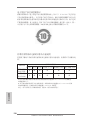
Dual Channel Memory Congurations
DDR3_A1 DDR3_A2 DDR3_B1 DDR3_B2
(Black Slot) (Black Slot) (Black Slot) (Black Slot)
(1) Populated - Populated -
(2) - Populated - Populated
(3)* Populated Populated Populated Populated
*
For the conguration (3), please install identical DDR3 DIMMs in all four
slots.
1. Please install the memory module into the slots DDR3_A2 and
DDR3_B2 for the rst priority.
2. If you want to install two memory modules, for optimal compatibility
and reliability, it is recommended to install them either in the set of
slots DDR3_A1 and DDR3_B1, or in the set of slots DDR3_A2 and
DDR3_B2.
3. If only one memory module or three memory modules are installed
in the DDR3 DIMM slots on this motherboard, it is unable to activate
the Dual Channel Memory Technology.
4. If a pair of memory modules is NOT installed in the same Dual
Channel, for example, installing a pair of memory modules in
DDR3_A1 and DDR3_A2, it is unable to activate the Dual Channel
Memory Technology .
5. It is not allowed to install a DDR or DDR2 memory module into
DDR3 slot; otherwise, this motherboard and DIMM may be dam-
aged.
6. If you adopt DDR3 2100/1866/1800/1600 memory modules on this
motherboard, it is recommended to install them on DDR3_A2 and
DDR3_B2 slots.

17
ASRock 970 Extreme3 R2.0 Motherboard
English
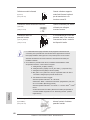
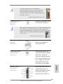
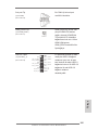
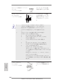
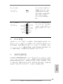
Installing a DIMM
Please make sure to disconnect power supply before adding or
removing DIMMs or the system components.
Step 1. Unlock a DIMM slot by pressing the retaining clips outward.
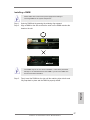
Step 2. Align a DIMM on the slot such that the notch on the DIMM matches the
break on the slot.
The DIMM only ts in one correct orientation. It will cause permanent
damage to the motherboard and the DIMM if you force the DIMM into
the slot at incorrect orientation.
Step 3. Firmly insert the DIMM into the slot until the retaining clips at both ends
fully snap back in place and the DIMM is properly seated.

18
ASRock 970 Extreme3 R2.0 Motherboard
English
2.4 Expansion Slots (PCI and PCI Express Slots)
There are 2 PCI slots and 4 PCI Express slots on this motherboard.
PCI Slots: PCI slots are used to install expansion cards that have the 32-bit PCI
interface.
PCIE Slots:
PCIE1 / PCIE3 (PCIE x1 slot) is used for PCI Express cards with x1
lane width cards, such as Gigabit LAN card and SATA2 card.
PCIE2 (PCIE x16 slot) is used for PCI Express x16 lane width graphics
cards, or used to install PCI Express graphics cards to support
CrossFireX
TM
function.
PCIE4 (PCIE x16 slot) is used for PCI Express x4 lane width cards,
or used to install PCI Express graphics cards to support CrossFireX
TM
function.
1. In single VGA card mode, it is recommended to install a PCI Ex-
press x16 graphics card on PCIE2 slot.
2. In CrossFireX
TM
mode, please install PCI Express x16 graphics
cards on PCIE2 and PCIE4 slots. Therefore, PCIE2 slot will work at
x16 bandwidth while PCIE4 slot will work at x4 bandwidth.
3. Please connect a chassis fan to motherboard chassis fan connec-
tor (CHA_FAN1, CHA_FAN2 or CHA_FAN3) when using multiple
graphics cards for better thermal environment.
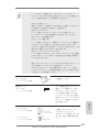
Installing an expansion card
Step 1. Before installing the expansion card, please make sure that the power
supply is switched off or the power cord is unplugged. Please read the
documentation of the expansion card and make necessary hardware
settings for the card before you start the installation.
Step 2. Remove the system unit cover (if your motherboard is already installed
in a chassis).
Step 3. Remove the bracket facing the slot that you intend to use. Keep the
screws for later use.
Step 4. Align the card connector with the slot and press rmly until the card is
completely seated on the slot.
Step 5. Fasten the card to the chassis with screws.
Step 6. Replace the system cover.

19
ASRock 970 Extreme3 R2.0 Motherboard
English
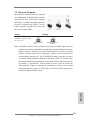
2.5 CrossFireX
TM
and Quad CrossFireX
TM
Operation Guide
This motherboard supports CrossFireX
TM
and Quad CrossFireX
TM
feature.
CrossFireX
TM
technology offers the most advantageous means available of
combining multiple high performance Graphics Processing Units (GPU) in a single
PC. Combining a range of different operating modes with intelligent software design
and an innovative interconnect mechanism, CrossFireX
TM
enables the highest
possible level of performance and image quality in any 3D application. Currently
CrossFireX
TM
feature is supported with Windows
®
XP with Service Pack 2 / Vista
TM
/
7 / 8 OS. Quad CrossFireX
TM
feature is supported with Windows
®
Vista
TM
/ 7 / 8 OS
only. Please check AMD website for AMD CrossFireX
TM
driver updates.
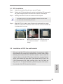
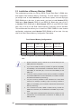
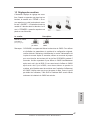
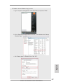
2.5.1 Graphics Card Setup
2.5.1.1 Installing Two CrossFireX
TM
-Ready Graphics Cards
Different CrossFireX
TM
cards may require different methods to enable CrossFi-
reX
TM
feature. For other CrossFireX
TM
cards that AMD has released or will release
in the future, please refer to AMD graphics card manuals for detailed installation
guide.
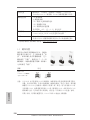
Step 1. Insert one Radeon graphics card into PCIE2 slot and the other Radeon
graphics card to PCIE4 slot. Make sure that the cards are properly seated
on the slots.
1. If a customer incorrectly configures their system they will not see the
performance benets of CrossFireX
TM
. All three CrossFireX
TM
components, a
CrossFireX
TM
Ready graphics card, a CrossFireX
TM
Ready motherboard and a
CrossFireX
TM
Edition co-processor graphics card, must be installed correctly
to benet from the CrossFireX
TM
multi-GPU platform.
2. If you pair a 12-pipe CrossFireX
TM
Edition card with a 16-pipe card, both
cards will operate as 12-pipe cards while in CrossFireX
TM
mode.

20
ASRock 970 Extreme3 R2.0 Motherboard
English
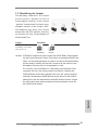
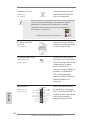
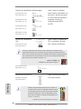
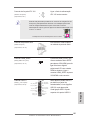
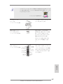
Step 3. Connect the DVI monitor cable to the DVI connector on the Radeon graph-
ics card on PCIE2 slot. (You may use the DVI to D-Sub adapter to convert
the DVI connector to D-Sub interface, and then connect the D-Sub monitor
cable to the DVI to D-Sub adapter.)
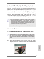
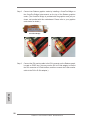
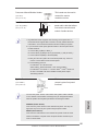
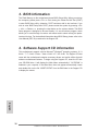
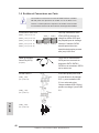
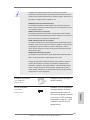
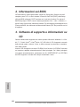
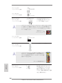
Step 2. Connect two Radeon graphics cards by installing a CrossFire Bridge on
the CrossFire Bridge Interconnects on the top of the Radeon graphics
cards. (The CrossFire Bridge is provided with the graphics card you pur-
chase, not bundled with this motherboard. Please refer to your graphics
card vendor for details.)
CrossFire Bridge
or
Page is loading ...
Page is loading ...
Page is loading ...
Page is loading ...
Page is loading ...
Page is loading ...
Page is loading ...
Page is loading ...
Page is loading ...
Page is loading ...
Page is loading ...
Page is loading ...
Page is loading ...
Page is loading ...
Page is loading ...
Page is loading ...
Page is loading ...
Page is loading ...
Page is loading ...
Page is loading ...
Page is loading ...
Page is loading ...
Page is loading ...
Page is loading ...
Page is loading ...
Page is loading ...
Page is loading ...
Page is loading ...
Page is loading ...
Page is loading ...
Page is loading ...
Page is loading ...
Page is loading ...
Page is loading ...
Page is loading ...
Page is loading ...
Page is loading ...
Page is loading ...
Page is loading ...
Page is loading ...
Page is loading ...
Page is loading ...
Page is loading ...
Page is loading ...
Page is loading ...
Page is loading ...
Page is loading ...
Page is loading ...
Page is loading ...
Page is loading ...
Page is loading ...
Page is loading ...
Page is loading ...
Page is loading ...
Page is loading ...
Page is loading ...
Page is loading ...
Page is loading ...
Page is loading ...
Page is loading ...
Page is loading ...
Page is loading ...
Page is loading ...
Page is loading ...
Page is loading ...
Page is loading ...
Page is loading ...
Page is loading ...
Page is loading ...
Page is loading ...
Page is loading ...
Page is loading ...
Page is loading ...
Page is loading ...
Page is loading ...
Page is loading ...
Page is loading ...
Page is loading ...
Page is loading ...
Page is loading ...
Page is loading ...
Page is loading ...
Page is loading ...
Page is loading ...
Page is loading ...
Page is loading ...
Page is loading ...
Page is loading ...
Page is loading ...
Page is loading ...
Page is loading ...
Page is loading ...
Page is loading ...
Page is loading ...
Page is loading ...
Page is loading ...
Page is loading ...
Page is loading ...
Page is loading ...
Page is loading ...
Page is loading ...
Page is loading ...
Page is loading ...
Page is loading ...
Page is loading ...
Page is loading ...
Page is loading ...
Page is loading ...
Page is loading ...
Page is loading ...
Page is loading ...
Page is loading ...
Page is loading ...
Page is loading ...
Page is loading ...
Page is loading ...
Page is loading ...
Page is loading ...
Page is loading ...
Page is loading ...
Page is loading ...
Page is loading ...
Page is loading ...
Page is loading ...
Page is loading ...
Page is loading ...
Page is loading ...
Page is loading ...
Page is loading ...
Page is loading ...
Page is loading ...
Page is loading ...
Page is loading ...
Page is loading ...
Page is loading ...
Page is loading ...
Page is loading ...
Page is loading ...
-
 1
1
-
 2
2
-
 3
3
-
 4
4
-
 5
5
-
 6
6
-
 7
7
-
 8
8
-
 9
9
-
 10
10
-
 11
11
-
 12
12
-
 13
13
-
 14
14
-
 15
15
-
 16
16
-
 17
17
-
 18
18
-
 19
19
-
 20
20
-
 21
21
-
 22
22
-
 23
23
-
 24
24
-
 25
25
-
 26
26
-
 27
27
-
 28
28
-
 29
29
-
 30
30
-
 31
31
-
 32
32
-
 33
33
-
 34
34
-
 35
35
-
 36
36
-
 37
37
-
 38
38
-
 39
39
-
 40
40
-
 41
41
-
 42
42
-
 43
43
-
 44
44
-
 45
45
-
 46
46
-
 47
47
-
 48
48
-
 49
49
-
 50
50
-
 51
51
-
 52
52
-
 53
53
-
 54
54
-
 55
55
-
 56
56
-
 57
57
-
 58
58
-
 59
59
-
 60
60
-
 61
61
-
 62
62
-
 63
63
-
 64
64
-
 65
65
-
 66
66
-
 67
67
-
 68
68
-
 69
69
-
 70
70
-
 71
71
-
 72
72
-
 73
73
-
 74
74
-
 75
75
-
 76
76
-
 77
77
-
 78
78
-
 79
79
-
 80
80
-
 81
81
-
 82
82
-
 83
83
-
 84
84
-
 85
85
-
 86
86
-
 87
87
-
 88
88
-
 89
89
-
 90
90
-
 91
91
-
 92
92
-
 93
93
-
 94
94
-
 95
95
-
 96
96
-
 97
97
-
 98
98
-
 99
99
-
 100
100
-
 101
101
-
 102
102
-
 103
103
-
 104
104
-
 105
105
-
 106
106
-
 107
107
-
 108
108
-
 109
109
-
 110
110
-
 111
111
-
 112
112
-
 113
113
-
 114
114
-
 115
115
-
 116
116
-
 117
117
-
 118
118
-
 119
119
-
 120
120
-
 121
121
-
 122
122
-
 123
123
-
 124
124
-
 125
125
-
 126
126
-
 127
127
-
 128
128
-
 129
129
-
 130
130
-
 131
131
-
 132
132
-
 133
133
-
 134
134
-
 135
135
-
 136
136
-
 137
137
-
 138
138
-
 139
139
-
 140
140
-
 141
141
-
 142
142
-
 143
143
-
 144
144
-
 145
145
-
 146
146
-
 147
147
-
 148
148
-
 149
149
-
 150
150
-
 151
151
-
 152
152
-
 153
153
-
 154
154
-
 155
155
-
 156
156
-
 157
157
-
 158
158


ASROCK 970 Extreme3 R2.0 Quick Installation Manual
- Type
- Quick Installation Manual
Ask a question and I''ll find the answer in the document
Finding information in a document is now easier with AI
in other languages
- italiano: ASROCK 970 Extreme3 R2.0
- français: ASROCK 970 Extreme3 R2.0
- español: ASROCK 970 Extreme3 R2.0
- русский: ASROCK 970 Extreme3 R2.0
- português: ASROCK 970 Extreme3 R2.0
- Türkçe: ASROCK 970 Extreme3 R2.0
- 日本語: ASROCK 970 Extreme3 R2.0
Related papers
-
ASROCK 970 Extreme3 R2.0 Installation guide
-
-
ASROCK 870iCafe User manual
-
ASROCK 870 EXTREME3 Owner's manual
-
ASROCK 970 Extreme3 Quick start guide
-
ASROCK 890GM Pro3 User manual
-
-
ASROCK A75M User manual
-
ASROCK H55 EXTREME3 User manual
-
ASROCK 985GM-GS3 FX Owner's manual
Other documents
-
ECS Geforce 9500GT Installation guide
-
ECS A990FXM-A DELUXE (V1.0) User manual
-
ECS A990FXM-A (V1.0) Specification
-
Biostar A68I-350 DELUXE R2.0 User manual
-
Apevia X-Pioneer User manual
-
AMD FD9370FHHKWOF User manual
-
-
Xigmatek Octans User guide
-
Asus P8H61-M User manual
-
Asus M5A97 User manual