Page is loading ...

85-03-01096
Cool Wall Vent Kit Installation Instructions
Cool Wall Vent Kits AA-11-04732, AA-11-04734 and AA-11-04735
Each Cool Wall termination kit must be used with AA-11-04060.
Approved for use with all Mendota Hearth ZC fireplace models, except M27.
NOTE: This kit must be installed by a qualified installer.
These instructions are to be used in conjunction with the fireplace installation manual to ensure proper
installation, framing dimensions adjustments and clearances to combustibles.
These kits are designed to use natural convection to transfer heated air from the front of the fireplace
to a different location. These kits allow the heated air from the fireplace to enter the room farther up on
the fireplace chase front wall or side wall. This results in much lower breastplate, mantel and wall
temperatures above the top convection chamber of the fireplace.
Note: When using FV34 (including Arch & Timberline Décor) and DXV 35 with 12”x 4” side discharge, the framing
depth will need to be increased. Refer to unit installation manuals before installing.
REQUIRED TOOLS FOR INSTALLATION
Phillips Screwdriver
Flat Screwdriver
1/4” Hex Head Driver
5/16” Hex Head Driver
Drill or Impact Driver

Page 2 of 18 85-03-01096
Table of Contents
REQUIRED TOOLS FOR INSTALLATION ............................................................................................................................ 1
GENERAL INFORMATION .................................................................................................................................................... 3
APPLICATION ..................................................................................................................................................................... 3
USE OF FIREPLACE FANS WITH THE COOL WALL KIT ................................................................................................. 3
KIT CONTENTS ...................................................................................................................................................................... 4
AA-11-04732 – 48” X 2” VENT BOX AND TRIM KIT .......................................................................................................... 4
AA-11-04734 – 36” X 2” VENT BOX AND TRIM KIT .......................................................................................................... 5
AA-11-04735 – DUAL 12” X 4” VENT BOX KIT .................................................................................................................. 6
PLANNING FOR VENT LOCATION ...................................................................................................................................... 7
TV Installation Above Fireplace ........................................................................................................................................... 7
Recommendation for Installing a Television Using a Cool Wall Vent Kit. .................................................................. 7
AESTHETIC CONSIDERATIONS ....................................................................................................................................... 9
AA-11-03781 – 48” X 2” VENT BOX AND TRIM KIT ................................................................................................. 9
AA-11-03782 – 36” X 2” VENT BOX AND TRIM KIT ............................................................................................... 10
AA-11-04062 – DUAL 12” X 4” VENT BOX KIT....................................................................................................... 10
MINIMUM FRAMING DIMENSIONS ................................................................................................................................. 11
48” X 2” & 36” X 2” & 12” X 4” VENT BOX AND TRIM KITS ................................................................................... 11
VENT HEIGHT ABOVE FIREPLACE ................................................................................................................................ 12
HORIZONTAL OFFSET ..................................................................................................................................................... 12
CLEARANCE TO FIREPLACE DIRECT VENT ................................................................................................................. 13
INSTALLATION INSTRUCTIONS ........................................................................................................................................ 13
PREPARING FIREPLACE FOR INSTALLATION OF KIT ................................................................................................. 13
PREPARING VENT COMPONENTS FOR INSTALLATION ............................................................................................. 15
INSTALLING THE VENT ................................................................................................................................................... 15
VERSIHEAT & FLEXHEAT INSTALLATION WITH COOL WALL .................................................................................... 17
FINISHING AROUND VENT BOX AND INSTALLING VENT TRIM/GRILL ...................................................................... 17

Page 3 of 18 85-03-01096
GENERAL INFORMATION
APPLICATION
These kits are designed to use natural convection to transfer heated air from the front of the fireplace to a different location.
The kits allow the heated air from the fireplace to enter the room farther up on the fireplace chase front wall or side wall.
This results in much lower breastplate, mantel and wall temperatures above the top convection chamber of the fireplace.
Three different Cool Wall Vent Kits are available: 48” x 2”, 36” x 2”, and a dual 12” x 4”
Each kit must be used in conjunction with AA-11-04060 venting components kit which must be ordered separately.
The 48” and 36” wide vent kits are intended to be used on the chase front wall above the fireplace.
The dual 12” x 4” vent kit is intended for installation on side walls. However, it can also be installed with the vents located
side by side on the front facing wall.
WARNING: The Cool Wall vents are approved for horizontal discharge only. They cannot be located in a ceiling or any
other unapproved application.
Cool Wall Vents can run at a 45-degree angle. NO HORIZONTAL VENT RUNS ARE ALLOWED.
WARNING: The Cool Wall vent can be located at a minimum of 6 inches below a ceiling. When the Cool Wall vent is
located this close to the ceiling, staining or streaking may occur on light colored ceilings due to dust in the air
flow.
To reduce the possibility of staining or streaking locate the Cool Wall vent farther down from the ceiling.
WARNING: Do not place any objects in front of, or on top of, the Cool Wall vent openings. The air discharged from the
Cool Wall vent is hot.
Never block the Cool Wall vent opening.
USE OF FIREPLACE FANS WITH THE COOL WALL KIT
Mendota Hearth fireplaces come with internal warm air convection blowers included.
When utilizing a Mendota Cool Wall kit to protect a television installation, other heat sensitive products or appliances, smooth
wall or slab stone wall finishes, the internal convection air blowers must be disconnected from power or programmed out of
the remote so that the internal blowers cannot be activated.
When a Cool Wall kit is installed on the fireplace and the internal blowers are turned on, the wall temperatures above the
fireplace will increase.
The internal blowers will force heated air out the front of the top convection opening on the fireplace, increasing the
temperatures on the breastplate, mantel and wall directly above the convection opening of the fireplace.
Increased temperatures on the breastplate, mantel and wall above the fireplace when the internal convection air blowers
are running is normal and safe.

Page 4 of 18 85-03-01096
KIT CONTENTS
AA-11-04732 – 48” X 2” VENT BOX AND TRIM KIT
This kit contains the following parts.
PART NUMBER DESCRIPTION QTY
HA-118-00006 48” X 2” VENT BOX 1
HA-118-00007 WALL COVER 1
50-01-00102 #8 X ½” SELF-DRILLING SCREW 4
85-03-01096 COOL WALL INSTALLATION INSTRUCTIONS 1
THE FOLLOWING ARE INCLUDED IN THE AA-11-04060 KIT.
45-01-00422 8” STARTER COLLAR 2
45-01-00421 8” X 24” VENT PIPE 2
45-01-00426 8” FLEX ALUMINUM VENT
25
FEET
HA-19-00268 COLLAR CLIPS 4
50-06-00162 8” HOSE CLAMP 4

Page 5 of 18 85-03-01096
AA-11-04734 – 36” X 2” VENT BOX AND TRIM KIT
This kit contains the following parts.
PART NUMBER
DESCRIPTION
QTY
HA-118-00008 36” X 2” VENT BOX 1
HA-118-00009 WALL COVER 1
50-01-00102 #8 X ½” SELF-DRILLING SCREW 4
85-03-01096 COOL WALL INSTALLATION INSTRUCTIONS 1
THE FOLLOWING ARE INCLUDED IN THE AA-11-04060 KIT.
45-01-00422 8” STARTER COLLAR 2
45-01-00421 8” X 24” VENT PIPE 2
45-01-00426 8” FLEX ALUMINUM VENT
25
FEET
HA-19-00268 COLLAR CLIPS 4
50-06-00162 8” HOSE CLAMP 4

Page 6 of 18 85-03-01096
AA-11-04735 – DUAL 12” X 4” VENT BOX KIT
This kit contains the following parts.
PART NUMBER
DESCRIPTION
QTY
HA-118-00010 12 X 4 VENT BOX 2
HA-118-00011 VENT EXTENSION 2
65-06-01453 12” X 4” SIDEWALL GRILL 2
50-01-00102 #8 X ½” SELF-DRILLING SCREW 8
85-03-01096 COOL WALL INSTALLATION INSTRUCTIONS 1
THE FOLLOWING ARE INCLUDED IN THE AA-11-04060 KIT.
45-01-00422 8” STARTER COLLAR 2
45-01-00421 8” X 24” VENT PIPE 2
45-01-00426 8” FLEX ALUMINUM VENT
25
FEET
HA-19-00268 COLLAR CLIPS 4
50-06-00162 8” HOSE CLAMP 4

Page 7 of 18 85-03-01096
PLANNING FOR VENT LOCATION
TV Installation Above Fireplace
Using a Cool Wall Kit can make it possible to install a television above your Mendota Hearth fireplace. These instructions
show Mendota’s recommendations for installing a television above the fireplace when using a Cool Wall Kit.
When planning to install a television or other heat sensitive product above your fireplace, there are some points to consider.
Many television manufacturers specify in their installation instructions that the television must not be installed near or above
a heat source. The decision to install a television near or above a Mendota Hearth fireplace rests solely on the consumer.
It is the consumer’s responsibility to satisfy television specifications and ensure the television will not exceed maximum
operation temperatures. Mendota Hearth will not be held liable for any adverse effects on a television or other heat sensitive
products or appliances located near a Mendota Hearth fireplace.
The image on the following page shows a recommendation that may be used as a guide for those consumers that decide
to locate a television above a Mendota Hearth fireplace. The recommendation has been found to reduce the heat impact to
a television when installed above a Mendota Hearth fireplace.
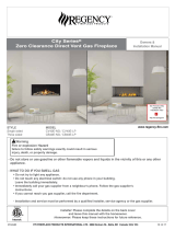
Recommendation for Installing a Television Using a Cool Wall Vent Kit.
WARNING: The internal convection air blowers that come standard in the fireplace must be turned off to ensure the heat
from the fireplace is redirected through the Cool Wall Vent Kit. Turning the convection air blowers on will force heated air
out the front of the fireplace, heating the surrounding area.
- On fireplaces with a millivolt system: DXV35 Timberfire, DXV42, DXV60, M50 the convection air blowers must be
disconnected from power to ensure they cannot be turned on.
- On fireplaces with an electronic ignition system that comes with a PF2 remote the convection air blower’s function
must be programed out of the remote. This will ensure that the convection blowers cannot be turned on. Follow
the directions below to remove the convection blower function from the remote.
1. Remove the battery from the remote.
2. Hold down both the ON/OFF key and MODE key
and reinstall the battery.
3. Continue to hold the ON/OFF key. Release the
MODE key. Press the MODE key once to
highlight the convection blower
function.
4. While still holding the ON/OFF key press the
DOWN ARROW key. The display will change
from “SET” to “CLR” to indicate that the
convection fan function has been disabled.
5. Release the ON/OFF key.

Page 8 of 18 85-03-01096
The Mendota Cool Wall system uses natural convection to take heat off the wall directly above the fireplace and redirects it
up and away from surrounding areas. Testing has shown that when using a Cool Wall system, temperatures above the
fireplace are reduced making it possible to mount a television 15” above the fireplace’s top air gap with no other wall
protection.
The internal convection air blowers must be disconnected from power or programmed out of the remote functions
for the Cool Wall Kit to perform correctly. If internal blowers are activated surface temperatures above the fireplace
will increase.
Note: The model depicted in the image is a representation of a Mendota Hearth fireplace. This recommendation applies to
all Mendota Hearth fireplaces.

Page 9 of 18 85-03-01096
AESTHETIC CONSIDERATIONS
You can choose from three different vent box outlet shape designs. Choose the vent box and trim kit that will look best when
installed with your fireplace and room décor.
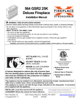
AA-11-04732 – 48” X 2” VENT BOX AND TRIM KIT
This vent box and trim kit is designed to be installed above the fireplace. The vent box has a simple slot opening that is 48”
wide and 2” tall. The vent box and trim kit come painted black but can be repainted to match room décor if desired using
high temperature paint.
It is recommended that the 48” vent box be used with fireplaces that have a glass width of close to 48” or more. However,
it can also be used on smaller fireplace if desired. For comparison, the drawings below show the 48” vent box and trim
installed over a ML72 fireplace and a FV34 fireplace.
ATTENTION: When installing the vent box kit over smaller fireplaces the minimum chase framing dimensions will
need to be increased to accommodate the vent. Be sure to understand all framing requirements of
the fireplace, vent box and trim kit before installation.
INSTALLED WITH ML72 FIREPLACE INSTALLED WITH FV34 FIREPLACE

Page 10 of 18 85-03-01096
AA-11-04734 – 36” X 2” VENT BOX AND TRIM KIT
This vent box and trim kit is designed to be installed above the fireplace. The vent box has a simple slot opening that is 36”
wide and 2” tall. The vent box and trim kit come painted black but can be repainted to match room décor if desired using
high temperature paint.
It is recommended that the 36” vent box is used with fireplaces that have a glass width less than 48”. However, it can also
be used on any fireplace if desired. For comparison, the drawings below show the 36” vent box and trim kit installed over a
ML72 fireplace and a FV34 fireplace.
ATTENTION: When installing the vent box and trim kit over smaller fireplaces the minimum chase framing
dimensions will need to be increased to accommodate the vent. Be sure to understand all framing
requirements of the fireplace, vent box and trim kit before installation.
INSTALLED WITH ML72 FIREPLACE INSTALLED WITH FV34 FIREPLACE
AA-11-04735 – DUAL 12” X 4” VENT BOX KIT
This dual vent box and trim kit is designed to be installed on a chase side wall. The dual vent box and trim kit can also be
installed above the fireplace on the front wall. The vent box and trim kit can be used with any fireplace. This vent box and
trim kit comes with two vent boxes that are each 12” wide and 4” tall. When installed the vent boxes are finished with a
louvered vent cover. The louvered cover comes painted white but can be repainted to match the room’s décor if desired
using high temperature paint. The drawings below show how this kit would look installed on a chase side or front wall.
INSTALLED ON A SIDE WALL INSTALLED ON THE FRONT WALL

Page 11 of 18 85-03-01096
MINIMUM FRAMING DIMENSIONS
In addition to these dimensions, consult the fireplace installation manual that the Cool Wall Vent will be installed
with. The minimum framing dimensions may need to be increased to accommodate the fireplace or vent kit. Be
sure to understand all factors that will affect the placement of the fireplace and these vent kits before beginning
construction.
It is critical when using a 48” x 2” or 36” x 2” discharge to check minimum framing dimensions for venting
capability.
NOTE: The Cool Wall systems have been designed to install Versiheat and FlexHeat from this platform. If using
these systems in conjunction, please refer to the manuals for those systems before framing, along with the manual
for the fireplace unit being installed.
48” X 2” & 36” X 2” & 12” X 4” VENT BOX AND TRIM KITS
Note: When using FV34 (including Arch & Timberline Décor) and DXV 35 with 12”x 4” side discharge, the framing
depth will need to be increased. Refer to unit installation manuals before installing.

Page 12 of 18 85-03-01096
VENT HEIGHT ABOVE FIREPLACE
The vent box must be located a minimum of 30 inches and up to 12 feet above the top of the fireplace.
HORIZONTAL OFFSET
When the vent box is placed in a location that requires the flex vent to be offset horizontally, a maximum 45° or 1:1 rise to
run ratio must be maintained. This is to ensure adequate air flow through the vent system. Support diagonal sections of the
flex duct with strapping every 24” to keep the flex duct from drooping.

Page 13 of 18 85-03-01096
CLEARANCE TO FIREPLACE DIRECT VENT
When planning the location of the Cool Wall vent box and trim kit be sure to consider how the fireplace exhaust vent system
is to be installed.
The Cool Wall vent has been designed for those locations that require a vertical vent that is taller than the vent
system. There is a pass thru area in the middle of the vent to allow the vertical pipe to pass thru on the 48” x 2” &
36” x 2” systems. (See picture below showing the opening)
INSTALLATION INSTRUCTIONS
PREPARING FIREPLACE FOR INSTALLATION OF KIT
1. Locate the two circular cutouts on top of the fireplace. Use a side cutter or tin snips to cut the tabs around the
perimeter of the circle and remove the cutout.

Page 14 of 18 85-03-01096
2. Next remove the insulation in the cutout to expose the fireplace’s top inner shield. This part also has a circular
cutout. Use a side cutter or tin snips to cut the tabs around the perimeter of the circle and remove the cut out.
3. Remove any loose pieces of insulation and push the insulation away from the inner cutout so that when the 8” rigid
venting is inserted into the fireplace all of the insulation fits around the vent pipe. Insert the 8” x 2’ rigid vent pipe
into the cutout on the fireplace. The vent pipe will sit on top of the inner shield. The cutout on the inner shield is
smaller than the vent pipe. Therefore, the vent will not pass through the inner shield cutout.
4. Use the collar clips and self-drilling screws to secure the vent pipe to the top of the fireplace. Make sure the vent
pipe is pushed down against the inner shield while attaching the collar clips.

Page 15 of 18 85-03-01096
PREPARING VENT COMPONENTS FOR INSTALLATION
1. Each kit comes with two 8” crimped starter collars. To install the starter collars, slide the end with the tabs through
the 8” holes on the bottom of the vent. Then, bend over all the tabs to hold the starter collar in place.
INSTALLING THE VENT
See the sections in these instructions PLANNING FOR VENT LOCATION and FRAMING DIMENSIONS. Follow
the information in these sections to plan out the installation before proceeding.
NOTE: These instructions show a 48” x 2” vent. The other vent sizes install in the same way.
1. After planning where the vent is to be placed, screw vent to framing. Mount bracket should be flush to framing. Be
sure to level from side to side for a good look.

Page 16 of 18 85-03-01096
2. The vent is fixed at ½” from framing surface. No adjustment to the vent installation is required to achieve the finish
depth. The finish of the wall can be up to 3” thick. The front vent cover is designed to fit the finish from ½” to 3”.
3. Next, use the flex vent to connect the vent pipe that was installed on top of the fireplace to the starter collars that
are located on the vent box. Cut the vent to length and pull it tight between the two connections. Use the 8” hose
clamps to hold the flex vent to the starter collars on the vent box and rigid pipe on the unit. In addition to the hose
clamps, a couple self-drilling screws can be used below the hose clamps to screw the flex vent to the rigid pipe and
starter collars.
ATTENTION: When running the flex vent with a horizontal offset a minimum 1-to-1 rise-to-run ratio must be
maintained.

Page 17 of 18 85-03-01096
VERSIHEAT & FLEXHEAT INSTALLATION WITH COOL WALL
ATTENTION: If installing one of these systems in conjunction with the Cool Wall refer to the installation manuals for the
corresponding system. Below is a picture showing where these systems are to be installed on the Cool Wall system.
FINISHING AROUND VENT BOX AND INSTALLING VENT TRIM/GRILL
ATTENTION: Finishing material used around the vent box can be up to 3” thick. FINSHING MATERIAL ABOVE VENT IN
PICTURE SHOWN ON NEXT PAGE REQUIRES NON-COMBUSTIBLE MATERIAL.

Page 18 of 18 85-03-01096
1. Place finishing material around the vent box up to the heat shield on top and bottom and up to the side edges of
vent box opening. Do not cover the opening of the vent box.
2. For 48” x 2” vent and 36” x 2” vent:
Once the finishing material is installed, install the vent trim by sliding the trim into the vent box opening. Push the
trim tight against the wall. Self-drilling screws can be used to secure the trim to the side of the vent box opening.
For 12” x 4” vent:
Once the finishing material is installed, the grill can be installed over the vent box opening. Center the grill over
the vent box opening and use the two included screws to secure the grill to the wall. Make sure that the louvers
on the grill are slanted upwards so you can’t see into the vent.
NOTE: The trims for the 48” x 2” and 36” x 2” vents box come painted black. The grill for the 12” x 4” vent
comes painted white. If desired, they can be repainted another color. High temperature paint
(>250°F) must be used. For additional information on acceptable paint types to use around the
fireplace and vent box, refer to the installation manual included with the fireplace.
/