RVP Coleman-Mach True Air 6535-344 Series Installation And Operating Instructions Manual
- Category
- Thermostats
- Type
- Installation And Operating Instructions Manual

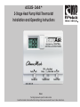
6535-344*
2-Stage Heat Pump Wall Thermostat
Installation and Operating Instructions
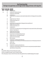
Notes:
*Last digit represents specific model number
Actual thermostat is black with white markings. Colors were reversed for use in these instructions.

1

1
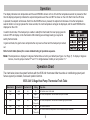
Operation
The display indicates room temperature and the word ROOM is shown on the LCD until the temperature selector is pressed; at that
time the display temporarily indicates the setpoint temperature and the word SET is shown on the LCD. Each time the UP arrow
is pressed, the setpoint will increase. Each time the DOWN arrow is pressed, the setpoint will decrease. Once the temperature
selector button is no longer pressed for a few seconds, the room temperature will again be displayed, and the word ROOM will be
displayed on the LCD.
In electric heat mode, if the heat pump is unable to satisfy the thermostat, the heat pump goes into
lockout. DIFF will display on the thermostat LCD indicating second stage heating is required to
satisfy the thermostat.
In gas heat mode, the gas furnace will provide the only source of heat and the heat pump is locked
out.
Refer to truth table (below) for a more detailed listing of operation sequence.
Note: The temperature is displayed in degrees Fahrenheit as a factory set default (see Figure 2 on Page 7). To display in degrees
Celsius, move the jumper marked “F” and “C” to bridge between middle pin and position “C.”
Mode Switch Fan Switch #1 Fan Switch #2 Calling Operation
1
Cool Auto Lo No No functions occur in this mode
2
Cool Auto Lo
Stage 1
1° Above Set
ID fan low, compressor #1 and OD blower low cycle as needed
3
Cool Auto Lo Stage 2
2° Above Set
ID fan low, compressor #1 and #2 and OD blower high cycle as needed
4
Cool On Lo No ID fan low continuous
5 Cool On Lo Stage 1
1° Above Set
ID fan low continuous, compressor #1 and OD blower low cycle as needed
Operation Chart
The chart below shows the system functions with the 6535-344• thermostat. After the entire air conditioning system (and
furnace system) is installed, check each position function.
6535-344* 2-Stage Heat Pump Thermostat Truth Table

2
3
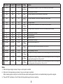
Mode Switch Fan Switch #1 Fan Switch #2 Calling Operation
6 Cool On Lo Stage 2
2° Above Set
ID fan low continuous, compressor #1 and #2 and OD blower high cycle as needed
7 Cool Auto Hi No No functions occur in this mode
8 Cool Auto Hi Stage 1
1° Above Set
ID fan high, compressor #1 and OD blower low cycle as needed
9 Cool Auto Hi Stage 2
2° Above Set
ID fan high, compressors #1 and #2 and OD blower high cycle as needed
10 Cool On Hi No ID fan high continuous
11 Cool On Hi Stage 1
1° Above Set
ID fan high continuous, compressor #1 and OD blower low cycle as needed
12 Cool On Hi Stage 2
2° Above Set
ID fan high continuous, compressors #1 and #2 and OD blower high cycle as needed
13 Off Auto Lo or Hi N/A No functions occur in this mode
14 Off On Lo N/A ID fan low continuous
15 Off On Hi N/A ID fan high continuous
16 Gas Heat Auto or On Lo or Hi No No functions occur in this mode
17 Gas Heat Auto or On Lo or Hi Stage 1
1° below set
Low gas heat will be energized to run
18 Gas Heat Auto or On Lo or Hi Stage 2
5° below set
Low gas heat and high gas heat will be energized to run*See note 2*
19 Elec Heat Auto or On Lo or Hi No Nothing is operating in this mode
20 Elec Heat Auto or On Lo or Hi Stage 1
1° below set
Heat pump will run ID fan high, Compressor #1 and #2 with reversing valve #1 and #2 and the OD fan
high
21 Elec Heat Auto or On Lo or Hi Stage 2
5° below set
Heat pump will run ID fan high, Compressor #1 and #2 with reversing valve #1 and #2, OD fan high and
low gas heat will be energized to run *See note 2 & 3*
22 Elec Heat Auto or On Lo or Hi Stage 3
7° below set
Heat pump will run ID fan high, Compressor #1 and #2 with reversing valve #1 and #2, OD fan high and
low and high gas heat will be energized to run *See note 2 & 3*
Notes:
1) When 2nd stage cooling is activated, it stays on until setpoint is satisfied.
2) When 2nd or 3rd stage heating is activated, it stays on until setpoint is satisfied.
When a heating stage is running for more than 20 minutes without reaching setpoint then the next available heating stage will be energized.
3) The word “DIFF” will display on the LCD when 2nd stage heat(Low gas furnace) is operating.

2
3
Setpoint Indoor Temp. Operation
70 70+ nothing is operating
$$$
69 heat pump turns on (primary heat source)
71 heat pump turns off (t’stat satisfied)
69 heat pump turns on
65 low gas furnace turns on (heat pump not able to satisfy thermostat) (first strike for 2nd stage electric heat counter)*See
note*
63 high gas furnace turns on *See note*
71 heat pump and gas furnace turn off
69 heat pump turns on
65 low gas furnace turns on (second strike for 2nd stage electric heat counter)*See note*
63 high gas furnace turns on*See note*
71 heat pump and gas furnace turn off
69 heat pump turns on
65 low gas furnace turns on and heat pump turns off (2nd stage electric heat counter reaches 3rd strike and the heat pump is
locked out for 2 hours)*See note*
63 high gas furnace turns on*See note*
71 gas furnace turns off (t’stat satisfied)
69 low gas furnace turns on (becomes primary heat source)
65 high gas furnace turns on as 2nd stage heat*See note*
71 gas furnace turns off (t’stat satisfied)
$$$
After 2 hour lockout
69 heat pump turns on (resumes as primary heat source)
65 Low gas furnace turns on and heat pump turns off (becomes primary heat source and the heat pump is locked out for
another 2 hours)
$$$
After 2 hour lockout
69 heat pump turns on (resumes as primary heat source)
71 heat pump turns off (t’stat satisfied) (2nd stage electric heat counter is reset anytime heat pump satisfies thermostat
setpoint and does not need gas furnace)
Note:
The word “DIFF” will display on LCD when 2nd stage heat is operating.
When 2nd or 3rd stage heat is activated, it stays on until setpoint is satisfied.
When a heating stage is running for more than 20 minutes without reaching setpoint then the next available heating stage will be energized.
Heat Pump Algorithm
To bring on Low gas furnace as 2nd stage heat and High gas furnace as 3rd stage heat

4
5
Setpoint Indoor Temp. Operation
70 70+ nothing is operating
$$$
69 low gas furnace turns on (primary heat source)
71 low gas furnace turns off (t’stat satisfied)
69 low gas furnace turns on
65 high gas furnace turns on (low gas heat not able to satisfy thermostat) (first strike for 2nd stage gas heat counter)*See
note*
71 low and high gas furnace turn off
69 low gas furnace turns on
65 high gas furnace turns on (second strike for 2nd stage gas heat counter)*See note*
71 low and high gas furnace turn off
69 low gas furnace turns on
65 high gas furnace turns on (2nd stage gas heat counter reaches 3rd strike and low gas furnace is locked out for 2 hours)
*See note*
71 low and high gas furnace turn off
69 low and high gas furnace turns on (becomes primary heat source)
71 low and high gas furnace turns off (t’stat satisfied)
$$$
After 2 hour lockout
69 low gas furnace turns on (resumes as primary heat source)
65 high gas furnace turns on (becomes primary heat source and low gas furnace is locked out for another 2 hours)*See note*
$$$
After 2 hour lockout
69 low gas furnace turns on (resumes as primary heat source)
71 low gas furnace turns off (t’stat satisfied)
(2nd stage gas heat counter is reset anytime low gas furnace satisfies thermostat setpoint and does not need high gas
furnace)
Note:
When 2nd stage heat is activated, it stays on until setpoint is satisfied.
When a heating stage is running for more than 20 minutes without reaching setpoint then the next available heating stage will be energized.
2-Stage Gas Heat Algorithm
High gas furnace as 2nd stage heat

4
5
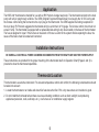
Application
The 6535-344* thermostat is intended for use with an RV Products 2 stage heat pump. The thermostat connects to the heat
pump with a 9-pin plug through a lifeline. The OEM (Original Equipment Manufacturer) must supply the 12 VDC wiring and
the furnace control wiring that connects to the 4-pin plug on the thermostat. The OEM supplies the mating receptacle for
the 4-pin plug. RV Products suggests the thermostat wiring be a minimum of 18 gauge. The furnace control circuit must not
exceed 1 amp. The thermostat is equipped with a replaceable fast-acting 2 amp fuse located on the base of the thermostat.
The fuse is designed to “open” if the furnace is mis-wired or if there is a short in the system. Before replacing the fuse, the
cause of the failure must be located and corrected.
Installation Instructions
BE SURE ALL ELECTRICAL POWER HAS BEEN DISCONNECTED FROM THE HEAT PUMP AND THE POWER SUPPLY.
These instructions are provided for the proper mounting of the thermostat itself. An Operation Chart (Pages 2 and 3) is
provided to show the thermostat capabilities.
Thermostat Location
This thermostat is a sensitive instrument. For accurate temperature control and comfort, the following considerations should
be taken into account:
1. Locate the thermostat on an inside wall about five feet above the floor. Pick a dry area where air circulation is good.
2. Do not install the thermostat where there are unusual heating conditions such as direct sunlight, heat producing
appliances (television, radio, wall lamp, etc.), or a furnace or air conditioner supply register.

6
7
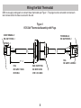
Figure 1
6535-344* Thermostat Assembly with Plugs
OEM must supply mating parts to connect these thermostats per Figure 1. The plugs must be connected to motorcoach
wire harness before the base is secured to the wall.
Wiring the Wall Thermostat
RAIN-TIGHT FITTING
REF. HEYCO # 3454
(FOR 1.1/8 D. HOLE)
SOCKET TERMINAL x7
REF. AMP # 170362-1
OR 794221-1
PLUG
REF. AMP # 172169-1
OR 794194-1
7" ±1
PLUG
REF. AMP # 1-480706-0
PIN TERMINAL x8
REF. AMP # 350218-1

6
7
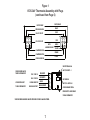
AUTO.
GENERATOR START
POS. 12 VDC OUT
NEG. 12 VDC OUT
COOLING HIGH FAN
COMPRESSOR ONE
COMPRESSOR TWO
COOLING LOW FAN
ELECTRIC HEAT
WHITE/BLACK
BLACK
BLUE
RED
GREEN
YELLOW
ORANGE
PURPLE
9
8
74
5
6
1
2
33
2
1
6
5
47
8
9
LIFELINE FROM UNIT
TO WALL THERMOSTAT.
COLORS SHOWN MATCH
THOSE ON THERMOSTAT
THESE TWO WIRE HARNESSES MUST BE PROVIDED BY VEHICLE MANUFACTURER.
POS. 12 VDC IN
NEG. 12 VDC IN
LOW GAS HEAT OUT
4 WIRE ASSEMBLY FROM
POWER SUPPLY AND FURNACE
TO WALL THERMOSTAT.
SOCKET TERMINAL x4
AMP P/N 350537-1
CAP HOUSING
AMP P/N 1-480703-0
WHITE
BLUE/WHITE
RED/WHITE
ORANGE/WHITE
HIGH GAS HEAT OUT
2
3
4
1
Figure 1
6535-344* Thermostat Assembly with Plugs
(continued from Page 6)

8
9
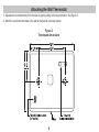
1. Separate the thermostat body from the base by gently pulling at the top and bottom. See Figure 2.
2. Attach the new thermostat base to the wall at the desired mounting location.
Figure 2
Thermostat dimensions
Attaching the Wall Thermostat

8
9

-
 1
1
-
 2
2
-
 3
3
-
 4
4
-
 5
5
-
 6
6
-
 7
7
-
 8
8
-
 9
9
-
 10
10
-
 11
11
-
 12
12


RVP Coleman-Mach True Air 6535-344 Series Installation And Operating Instructions Manual
- Category
- Thermostats
- Type
- Installation And Operating Instructions Manual
Ask a question and I''ll find the answer in the document
Finding information in a document is now easier with AI
Other documents
-
Lennox International Inc. icomfort Wi-Fi User manual
-
Lennox DAVE LENNOX SIGNATURE COLLECTION GAS FURNACE User manual
-
Lennox SL280UH070V36A User manual
-
-
Airxcel 9630-352 Installation, Operation & Application Manual
-
Lennox Harmony III Installation Instructions Manual
-
-
Lennox Elite G61MPV36C-090 User manual
-
Trane Charge Assist User manual
-
White Rodgers 1F95CA-391 User manual