Product Guid
FLAT PANEL DISPLAY 19-inch
GPD-U64EM-DC2
Thank you for purchasing this product. The product you have purchased consists of the
following items.
Check, with the following list, that your package is complete.
If you find any item either missing or damaged, please contact the sales representative you
purchased the product from.
1. About the Product
This product is a 19-inch On-Screen Display with a high-performance touch screen.
As an indicator you can touch the screen with your finger and operate like a tablet PC, this
product can be used to control production lines, provide work instructions, manage access,
in addition to operate industrial devices through the screen.
2. Product Configuration
This product consists of the items listed below.
Check, with the following list, that your package is complete. If you discover damaged or
missing items, contact your retailer.
Product…1 Product Guide
(this sheet)…1
Warranty Certificate…1
USB Cable For Touch
Screen 1.8m (A – B t
pe)
…1
VGA Cable 1.8m…1
3. Safety Precautions
This document provides safety information using the following symbols to prevent
accidents resulting in injury or death and the destruction of equipment and resources.
Understand the meanings of these labels to operate the equipment safely.
DANGER
DANGER indicates an imminently hazardous situation
which, if not avoided, will result in death or serious
injury.
WARNING
WARNING indicates a potentially hazardous situation
which, if not avoided, could result in death or serious
injury.
CAUTION
CAUTION indicates a potentially hazardous situation
which, if not avoided, may result in minor or moderate
injury or in property damage.
Handling Precautions
WARNING
Always check that the power supply is turned off before connecting or disconnecting
power cables.
This product is not intended for use in aerospace, space, nuclear power, medical
equipment, or other applications that require a very high level of reliability. Do not use
the product in such applications.
If using this product in applications where safety is critical such as in railways, automotive,
or disaster prevention or security systems, please contact your retailer.
Do not perform keypad operations on the touch screen that may threaten human life or
serious damage. Please design a system that can deal with incorrect key input operations.
CAUTION
Do not use or store this product in a location exposed to high or low temperature that
exceeds range of specification or susceptible to rapid temperature changes.
Example: Exposure to direct sun In the vicinity of a heat source
Do not use this product in extremely humid or dusty locations. It is extremely dangerous
to use this product with its interior penetrated by water or any other fluid or conductive
dust. If this product must be used in such an environment, install it on a dust-proof
control panel, for example.
Avoid using or storing this product in locations subject to shock or vibration that exceeds
range of specification.
Do not use this product in the vicinity of devices that generate strong magnetic force or
noise. Such products will cause this product to malfunction.
Do not use or store this product in the presence of chemicals.
To clean this product, wipe it gently with a soft cloth dampened with either water or mild
detergent. Do not use chemicals or a volatile solvent, such as benzene, thinner,
ammonia, or a strong chlorinated solvent to prevent pealing or discoloration of the paint.
This product’s case may become hot. To avoid being burned, do not touch that section
while this product is in operation or immediately after turning off the power. Avoid
installation in a location where people may come into contact with that section.
In the event of failure or abnormality (foul smells or excessive heat generation), unplug
the power cord immediately and contact your retailer.
Do not use any sharp-pointed object such as a mechanical pencil to touch the touch
panel. Doing so may scratch the touch panel, resulting in malfunctions.
Do not subject the touch screen to shock as doing so may break it.
Use your fingers to perform operations on the touch screen.
Operations with the stylus pen on the touch screen might not perform well due to the
pen you are using with.
LCD may have a few bright spots that are always on or a few black spots that are always
off. Color irregularity may also occur depending on the viewing angle. This however is
due to the structural characteristics of the LCD; therefore, it is not a product fault.
As a characteristic feature of the capacitive touch screen, the sensor may become
unstable due to the influence of surrounding metal or electrically floating metal objects,
and this might lead to shifting the detection position. In this case, perform calibration
again for the touch-panel screen to reset the calibration data.
The backlight of the touch screen and the display have limited lifetime. Therefore, that
they need to be inspected regularly.
- The lifetime of the consumable parts
Backlight --- Display brightness decreases over time with use.
If the luminance setting is 100 and the ambient temperature is 40 ° C, the brightness
drops to 50% in 30,000-hour use.
* For expendables replacement, contact your retailer as it must be performed as
a process of repair (there will be a charge).
- LCD faults
LCD may have a few bright spots that are always on or a few black spots that are
always off below a certain standard. This however is due to the structural
characteristics of the LCD; therefore, it is not a product fault.
Standard :
The number of bright spots≤2, The number of two consecutive bright spots ≤
1, The total number of bright spots≤2, The distance between two bright spots
≥15mm
The number of black spots ≤5, The number of two consecutive black spots ≤2,
The total number of black spots ≤5, The distance between two black spots ≤
15mm
The number of bright and black spots ≤5, Bright and black spots on the line :
Non-enterable
- Burn-in on TFT Display
“Burn-in” may occur if the same display is retained for a long time. Avoid this by
periodically switching the display so that the same display is not maintained for a
long time.
* Burn-In : Phenomenon characterized by a TFT display as a result of long-time
display of the same screen where a shadow-like trace persists because electric
charge remains in the LCD element even after the patterns are changed.
- About MTBF
50323 Hrs
VCCI Class B Notice
この装置は、クラスB機器です。この装置は、住宅環境で使⽤することを⽬的としてい
ますが、この装置がラジオやテレビジョン受信機に近接して使⽤されると、受信障害
を引き起こすことがあります。
取扱説明書に従って正しい取り扱いをしてください。
VCCI-B
FCC PART 15 Class B Notice
NOTE
This equipment has been tested and found to comply with the limits for a Class
B digital device, pursuant to Part 15 of the FCC Rules. These limits are designed
to provide reasonable protection against harmful interference in a residential
installation. This equipment generates, uses and can radiate radio frequency
energy and, if not installed and used in accordance with the instructions, may
cause harmful interference to radio communications. However, there is no
guarantee that interference will not occur in a particular installation.
If this equipment does cause harmful interference to radio or television recep-
tion, which can be determined by turning the equipment off and on, the user is
encouraged to try to correct the interference by one or more of the following
measures:
-- Reorient or relocate the receiving antenna.
-- Increase the separation between the equipment and receiver.
-- Connect the equipment into an outlet on a circuit different from that to which
the receiver is connected.
-- Consult the dealer or an experienced radio/TV technician for help.
FCC WARNING
Changes or modifications not expressly approved by the party responsible for
compliance could void the user's authority to operate the equipment.
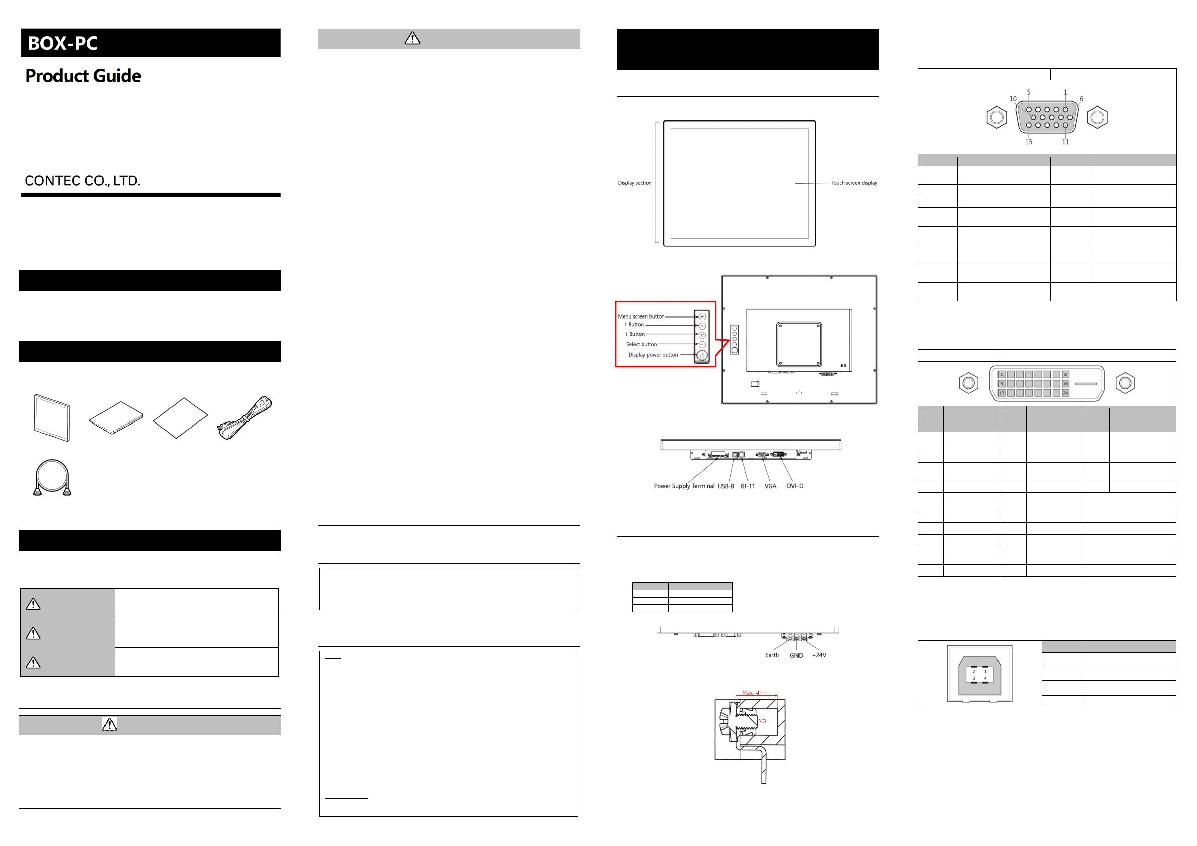
4. Product Nomenclature and
Function
Nomenclature of Product Components
<Front>
<Rear>
<Bottom>
Description of Product Components
<Power Supply Terminal >
When connecting the power line with the power supply terminal, ensure to align them with
the proper polarities.
Reverse polarities can result in damages to the product.
Pin Description
1 +24V
2 GND
3 FG
Maker : DECA Model : T55-O-03
* For the FG terminal, connect FG cable. It is conducted with ground (GND) signal.
If you lost cable fixing screws, get a screw within 4 mm thread length.
<VGA Connector>
This product has a connector for display connections. The connector name is VGA (15-pin
HD-SUB).
Use the bundled display cable to connect this with the PC.
Connector t
pe 15-pin HD-SUB (FEMALE)
Pin number Si
nal name Pin number Si
nal name
1 Red video signal input 9
+5V: Input from host system
for the VESA DDC2B function
2 Green video si
nal input 10 Si
nal
round
3 Blue video si
nal input 11 N.C.
4 N.C. 12
SDA signal input for the VESA
DDC2B function
5
DDC ground for the VESA
DDC2B function
13
Horizontal signal input from
host s
stem
6
Analog signal ground for the red
video
14
Vertical signal input from host
s
stem
7
Analog signal ground for the
reen video
15 DDCCLK
8
Analog signal ground for the
blue video
<DVI-D Connector>
This product has a connector for DVI-D connections.
The bundled display cable cannot be used for this.
Connector t
pe DVI-D connector 24-pin (FEMALE)
Pin
num-
ber
Signal name Pin
num-
ber
Signal name Pin
num-
ber
Signal name
1 TMDS DATA2- 11
TMDS Data 1
3
Shield
21 TMDS DATA5+
2 TMDS DATA2+ 12 TMDS DATA3- 22 TMDS Clock Shield
3
TMDS Data 2/4
Shield
13 TMDS DATA3+ 23 TMDS Clock+
4 TMDS DATA4- 14 +5V DDC Power 24 TMDS Clock-
5 TMDS DATA4+ 15
GND (+5V, Analog
V/H S
nc)
6 DDC Clock 16 Hot Plu
Detect
7 DDC Data 17 TMDS DATA0-
8 NC 18 TMDS DATA0+
9 TMDS DATA1- 19
TMDS Data 0/5
Shield
10 TMDS DATA1+ 20 TMDS DATA5-
<USB Connector>
This product has a connector (TYPE-B) for a touch screen. Use the bundled USB cable for
touch screen to connect this with the PC.
(One side of the display cable is already connected to the display section upon shipping.
Connect the other end of the cable to the USB connector on the PC.)
Pin number Si
nal name
1 +5V (INPUT)
2 DATA-
3 DATA+
4 GND
<RJ-11 Connector>
This connector is not used for the product.

