Kessler-Ellis Products MS817 Installation and Operating Instructions
- Type
- Installation and Operating Instructions


INDEX
DESCRIPTION ................................................................................... 1
SPECIFICATIONS ............................................................................... 1
WIRING HOOKUP ............................................................................... 1
INPUT & OUTPUT SETTINGS ............................................................ 2
REMOVING THE CASE .......................................................... 2
OUTPUT ADJUSTMENTS ...................................................... 2
LED INDICATOR ...................................................................... 2
DIMENSIONS ..................................................................................... 3
WARRANTY ....................................................................................... 3
DECODING PART NUMBER ............................................................. 3

Raw Signal
Flowmeter
with Magnetic Pickup
MS817
Mag Pickup Input
1
2
7
9
10
8
+
–
Conditioned
Pulse
Output
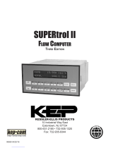
Description:
The model MS817 is a signal conditioner which permits the user
to condition and scale the input pulses from a pulse producing
sensor into a high level output where each pulse represents an
engineering unit of measure.
Several pulse input types are supported including magnetic
pickup, contact closure, and an isolated pulse input.
The pulse output is a nominal square signal.
The pulse output is available in isolated and non-isolated versions.
User selections include output pulse and internal pullup resistors.
The user may select his pulse output conguration by means of
a dip switch.
The unit is powered to 8 - 35 VDC. Reverse polarity protection is
provided. A power indicator is provided.
The unit is available in enclosures intended for either DIN rail,
NEMA4X or Explosion Proof.
Specications:
Pulse Input:
Isolated Pulse:
Logic 1 (high): 3 - 30 VDC
Logic 0 (low): 0 - 1 VDC
Input Frequency Range: 0-10000 Hz
Input Impedance: 3.3 k Ω
Reverse Polarity Protection
Isolation Voltage: 500 V
Contact Closure:
Switch Debounce: 40 CPS maximum count rate
10000 ohm internal pullup to 5 VDC
Magnetic Pickup:
Sensitivity: 30 mV p-p
Bandwidth: 0-3500 Hz
Over Voltage Protection to 30 VDC
10 Kohm input resistance
Pulse Output:
Pulse Duration: Nominal 50/50 duty cycle
Open Collector Pulse:
Maximum Voltage: 48 VDC
Maximum Current: 100 mA @ .1.5 VDC (typ.)
Max. Output Speed: 10 kHz
Reverse Polarity Protection
Overcurrent Protection
Jumper selectable for 5 V and 24 V pulse output
Isolated Pulse:
Maximum Voltage: 30 VDC
Maximum Current: 10 mA
Max. Output Speed: 1 kHz
Isolation Voltage: 500 VDC
Reverse Polarity Protected
Power Input:
Input Voltage Range: 8.5 to 35 VDC
Supply Current: 25 mA (nominal)
Reverse Polarity Protection
Transient Protection
Pulse Scaling:
NONE - Output is a conditioned version of the pulse input
Mounting Styles
DIN Rail Mount: Plastic enclosure with a snap fastener for
tting to DIN 46 277 and DIN EN 50 022
assembly rails.
NEMA 4X: 4.92” x 4.92” NEMA 4X Enclosure for wall
mounting.
Explosion Proof: Aluminum enclosure for:
Class I, Division 1, Groups B, C & D
Class II, Division I, Groups E, F & G.
Listing: CE Compliant
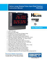
Simplied Block Diagram
Wiring:
1 2 3
4 5 6
7 8 9
10 11 12
Magnetic pickup
Magnetic pickup
Contact Closure Input
Common
Opto-isolator In (+)
Opto-isolator In (–)
(+) DC Power Input
DC Power Input Common
Pulse Output (+)
Common
Isolated Pulse Out (+)
Isolated Pulse Out (–)
+
–
mV
Input
3-30V
Input
3.3k7
10k7
10k7
LPF
Contact
Closure
5 V
Regulator
Isolated Pulse
Output
Pulse
Output
DC
Input
1
2
5
6
3
4
7
8
9
10
11
12
+5V
+
–
+
–
+
–
+
–
Typical Application:

REMOVING THE CASE:
The case must be removed to change switch settings. To remove the case proceed as follows:
Refer to FIGURE 1. Using nger tips, carefully pry the case away from the terminal blocks (as shown with dotted
lines).
Pry far enough to release the restraining clips on both sides of the case.
Press up on terminal block with thumbs. The assembly will pop out allowing it to be removed from case.
INPUT & OUTPUT SETTING
1 2 3 4
ON
10 11 12
1 2 3
4 5 6
7 8 9
Power
LED
DIP Switch for Selecting
Pull-Up Resistors
FIGURE 1 FIGURE 2
INTERNAL PULLUP RESISTOR VOLTAGE
(for pulse output)
Internal pullup resistors are congurable with dip switch
settings. Refer to the following tables to congure the unit
for your application:
S3 S4 Pulse Output Voltage
ON OFF 5 VDC
OFF ON 24 VDC
OFF OFF Open Collector
POWER LED INDICATOR:
The MS817 has a power LED to indicate the power
status of the unit. The table below describes the various
states for the LED.
POWER LED MEANING
OFF The unit is off.
ON (constant) The unit is loop powered.

Ordering Information
Example MS817 1 B ET
Series
Output Type
1 = Open Collector & Isolated Pulse (STD)
Mounting:
B= Nema 4X
C= Explosion Proof
D= DIN Rail
Options:
ET= Extended Temp: -4° to 185°F (-20° to 85° C)
T = Third 3/4” conduit entry for Explosion Proof Housing
H2 = 0.875” Hole for NEMA4 mounting style
HF2 = 0.5” Female NPT Hub tting
H3 = 1.125” Hole for NEMA4 mounting style
HF3 = 0.75” Female NPT Hub tting
Accessories: (add to end of part number)
DR-4= 4” DIN Rail
Dimensions
3.88 (98.5)
2.95 (75)
1.40 (35.5)
.89
(22.5)
DIN Rail Mount
4.92
(125)
4.92
(125)
4.21
(107)
4.21
(107)
Mounting holes molded
directly under cover screws.
Max. screw head .29"
(Typ. 4 places)
TOP VIEW
PANEL INSTALLED
To access terminals, remove
cover and 4 panel screws.
2.95
(75)
1.93
(49)
.18 (5)
.43
(11)
SIDE VIEW
Optional holes
or hub fitting
NEMA4X
4.75 -5
(121 - 127)
4.9 - 5.25
(124 - 133)
5.9 - 7.7
(150 - 196)
3/4” NPT (2) HLS.
(feed thru hubs)
All Dimension in inches (mm)
Optional 3rd
Conduit Entry
Explosion Proof Enclosure
WARRANTY
This product is warranted against defects
in materials and workmanship for a period
of two (2) years from the date of shipment
to Buyer. The Warranty is limited to repair
or replacement of the defective unit at the
option of the manufacturer. This warranty is
void if the product has been altered, misused,
dismantled, or otherwise abused. ALL OTHER
WARRANTIES, EXPRESSED OR IMPLIED,
ARE EXCLUDED, INCLUDING BUT NOT
LIMITED TO THE IMPLIED WARRANTIES
OF MERCHANTABILITY AND FITNESS
FOR A PARTICULAR PURPOSE
Kessler - Ellis Products Co.
10 Industrial Way East
Eatontown, NJ 07724
(732) 935 - 1320
Toll Free 800 - 631 - 2165
Fax (732) - 935 - 9344
-
 1
1
-
 2
2
-
 3
3
-
 4
4
-
 5
5


Kessler-Ellis Products MS817 Installation and Operating Instructions
- Type
- Installation and Operating Instructions
Ask a question and I''ll find the answer in the document
Finding information in a document is now easier with AI
Related papers

Other documents
-
 KEP SC-FI Series User manual
-
 KEP BAT R/T Millennium-S1 Installation And Operating Instrictions
-
 KEP SUPERtrol II User manual
-
Omega DPF500 Series User manual
-
 PRECISION DIGITAL PD6830 User manual
-
 PRECISION DIGITAL PD6830 User manual
-
Eurotherm Action Instruments Product Handbook HA136731 Owner's manual
-
Fluidwell F131-P User manual
-
 PRECISION DIGITAL PD2-6300 User manual
-


