Page is loading ...

Doc. No. 502-20-0115-001 Iss 6. Jan 2016. (CN39819-001)
Installation and User Guide
Rugged VoIP Telephone
Titan, Commander, VR and Help Point models
IMPORTANT
THESE PRODUCTS MUST BE CONFIGURED PRIOR TO
INSTALLATION
PLEASE READ THIS GUIDE FIRST
GAI-TRONICS
A division of Hubbell Ltd.
Titan Commander
Vandal Resistant Help Point

VoIP Telephone. 2
CONTENTS
1.
Safety and Care Information ....................................................................... 4
2.
Features ..................................................................................................... 4
3.
Quick Start Guide ....................................................................................... 7
4.
Alternative Configuration Methods.............................................................. 9
5.
Mounting methods and dimensions ............................................................ 9
5.1.
General ........................................................................................ 9
5.2.
Titan ........................................................................................... 10
5.3.
Commander ............................................................................... 15
5.4.
VR and Help Point ...................................................................... 18
6.
Connections and Installation .................................................................... 20
6.1.
General ...................................................................................... 20
6.2.
IMPORTANT SAFETY INFORMATION ..................................... 21
6.3.
Emergency Services warning ..................................................... 22
6.4.
Titan Installation ......................................................................... 22
6.5.
Titan Connections ...................................................................... 23
6.6.
Commander Installation ............................................................. 24
6.7.
Commander Connections ........................................................... 26
6.8.
VR and Help Point Installation .................................................... 27
6.9.
VR and Help Point Connections ................................................. 28
7.
Cleaning ................................................................................................... 29
7.1.
Normal Cleaning ........................................................................ 29
7.2.
Stainless Steel Push-buttons ..................................................... 29
7.3.
Graffiti......................................................................................... 29
7.4.
Anti-Graffiti Coating .................................................................... 29
8.
Aftercare ................................................................................................... 29
9.
Technical Specifications ........................................................................... 30

3 VoIP Telephone.
9.1.1
Australian standards .................................................................. 33
10.
CE Declaration ......................................................................................... 34
11.
Licensing Notes ........................................................................................ 35

VoIP Telephone. 4
1. Safety and Care Information
▲
IMPORTANT:
THIS PRODUCT CAN CONTAIN HAZARDOUS VOLTAGES. IT IS
ESSENTIAL THAT THE WATERPROOF SEAL IS PROPERLY MADE
DURING INSTALLATION, TO ENSURE THAT WATER CANNOT GET
INTO THE ENCLOSURE. THE INGRESS OF WATER CAN CAUSE
ACCESSIBLE PARTS OF THE TELEPHONE TO BECOME LIVE, AND
THEREFORE MUST BE PREVENTED AT ALL COSTS.
▲
Please read these
instructions thoroughly before starting installation.
These products must be installed by competent personnel familiar
with electrical and network installations.
▲
Refer to safety information is section
6.2
if hazardous voltag
es (eg
mains) are to be connected to this product.
▲
Make sure that correctly
-
sized cable glands are used, and that cables
are securely clamped in the clamps provided. Failure to do so could
result in an unsafe installation.
▲
Take adequate precautions wh
en opening the case or installing
.
Isolate connections elsewhere before opening.
▲
The spring
-
loaded door (Titan models only, where fitted) can close
sharply. Take care not to trap fingers etc., during installation and use.
▲
CAUTION (handse
t versions): small metal objects may stick to the
handset: please check before use.
2. Features
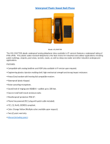
This manual describes the voice over internet protocol (VoIP) versions of the
Titan, Commander, Vandal Resistant (handsfree) and Help Point telephone
ranges. Features include:
• SIP compatible (RFC3261)
• Automatic outgoing call diversion (memory list)
• Weather and vandal resistant
• Wide operating temperature range
• Real-time alarm reporting via email or Syslog
• Power over Ethernet compatible
• Configurable via web page, serial link or download
• 4 auxiliary inputs, 2 volt-free contact outputs
Models are available with different casing, keypad and handset options.

5 VoIP Telephone.
Titan, aluminium-bodied handset telephone
Commander, rugged glass-reinforced polyester handset telephone:

VoIP Telephone. 6
Vandal Resistant (VR) handsfree telephone:
FRONTPLATE
MICROPHONE
SPEAKER
LED
FLUSH, 25mm
CALL BUTTON
Help Point handsfree telephone:
FRONTPLATE
MICROPHONE
SPEAKER
LED
REAR
ENCLOSURE
PALM-OPERABLE,
STAINLESS STEEL
CALL BUTTONS

7 VoIP Telephone.
3. Quick Start Guide
IMPORTANT
THESE UNITS MUST BE CONFIGURED BEFORE THEY ARE INSTALLED.
All units have identical settings as factory defaults, so each one must be
individually configured to give it a unique identity on the network. This may
be difficult to do after the units are installed.
The general sequence for set up and use is:
Stage Comment
1.
Initial network configuration
Essential
. Each phone must be set up for the
network prior to installation. Each unit is
usually dedicated to a specific location - make
sure each configured phone is identified ready
for installation. Refer to configuration guide
(available from website).
2.
Change user name and
password
Recommended
, to prevent unauthorised
changes to the phone's configuration. Make
sure to record these details securely. Refer to
configuration guide (available from website).
3.
Check for power and
network.
Ensure that a network port is available within
95m of intended installation. Ensure that a
power source is available (either local 24-48V
DC or PoE). Refer to section 9.
4.
Mounting Physical mounting at the intended location.
Refer to section 5.
5.
Installation Connections and cabling. Connection to the
network at the intended location. Refer to
section 6.
6.
Final configuration (can also
be done prior to installation)
Setting autodial numbers, etc. Can be done
remotely. Refer to configuration guide
(available from website).
7.
Test Check that calls can be made successfully
8.
Maintain Monitor alarms. Set up auto-updates. Refer to
configuration guide (available from website).
The easiest way to get started is to make a network connection to the unit and log
on via a web browser.

VoIP Telephone. 8
The unit is initially set with a static IP address:
IP address 192.168.1.2
It will request a user name and password, the initial factory settings are:
User Name user
Password password
The phone’s home page is as shown below, and allows access to all the other
configuration pages. Use the Network IP Settings page to change IP settings
appropriate for the intended network.
IMPORTANT: After changing the IP address of the telephone you will need to
browse to the new IP address to access the configuration, instead of the
default 192.168.1.2.
IMPORTANT: If DHCP is enabled, ensure that there is a suitable DHCP server
available on the network and that you have a means by which to discover the
IP address of the telephone allocated by the DHCP server. There is no other
way to access a DHCP enabled VoIP telephone over the network without
being able to find the IP address allocated by the DHCP server.
Full help is available from
www.gai-tronics.org/support/voip-support/

9 VoIP Telephone.
4. Alternative Configuration Methods.
There are 3 methods for configuring GAI-Tronics VoIP telephones: -
• Web pages
• Configuration file
• Command Line interface (CLI)
Web pages (held within the telephone) can be accessed over the network using a
browser such as Internet Explorer™, to view and change settings within a single
unit.
Configuration files are ASCII text files containing configuration options that can be
read and edited by a knowledgeable user using any plain text editor such as
Notepad™. The telephone can automatically download a configuration file from the
network, providing a controlled method of configuring multiple telephones.
The telephone can also be configured using a command line interface, either via the
local serial port or remotely via a TELNET session over the network. The initial
default settings for the serial port are :
Speed: 115200
Data bits: 8
Stop bts: 1
Parity No
The complete syntax and command structures of configuration files and the CLI are
included in the Configuration guide available from
www.gai-tronics.org/support/voip-support/
5. Mounting methods and dimensions
5.1. General
IMPORTANT
Installation details differ between the product ranges –please make
sure you know which product you are installing and refer to the
appropriate sections below.
Before mounting the telephone, check the cable routing and requirements. Fit
gland(s) to the case as follows:
1. Remove the RED blanking plug leaving the other (usually BLACK) in
place.
Only fit a second gland if any external inputs or outputs are being used –
cables for these should be routed through a separate gland to the network
cable.
2. Note that 2 plastic glands are supplied, but it is the installer’s responsibility
to select the correct type of gland for the application and cables used. The
gland entries (and the supplied glands) are M20.

VoIP Telephone. 10
3. Select the appropriate sized gland:
Use the smaller gland for cables
diameters 4 - 7mm (0.16 – 0.27in).
Use the larger gland for cable
diameters 8 - 13mm (0.3 – 0.5in).
4. From the outside of the case, insert
the selected gland into the threaded
cable entry hole and tighten, so that
its sealing washer is compressed
against the enclosure surface.
5. Proceed with chosen mounting method below
IMPORTANT
Glands are essential to clamp cables and to ensure a weatherproof seal.
It is the installer’s responsibility to make sure they are correctly selected
and fitted. Failure to do so could result in an unsafe installation.
5.2. Titan
As standard, Titan with rear enclosure is supplied with 2 cable glands with
sealing washers, 4 countersunk screws with wall plugs and a 3mm Allen key.
Titan telephones supplied for flush mounting have no rear enclosure – see
section 5.2.3 below.
5.2.1 Wall mounting

11 VoIP Telephone.
1. Using a suitable tool, punch out 4 holes in the rear enclosure, taking
care not to damage or dislodge the plastic bushes. Only four of the
eight holes are required - the outer ones are recommended. The
inner holes are provided to be compatible with older-style mounting
posts, and should be left intact if not used. If the inner holes are
used they must be fitted with the supplied plastic bushes.
WARNING:.An unsafe condition could occur (and your warranty will be
invalidated) if :-
1. Any fixing hole made in the rear enclosure is left unused.
2. Any additional holes are drilled into the telephone enclosure.
3. Plastic bushes are not used on all fixing holes.
2. Mark the wall with hole centres based on the dimensions shown
(145 x 270mm, 5.7 x 10.63in). If necessary offer the rear enclosure
up to the wall to check alignment. Do not use the enclosure as a
template for drilling.
3. Drill holes in the wall on the marked positions. Select appropriate
screws, wall plugs etc., for the type of wall, bearing in mind that the
weight of the complete phone is around 5kg (11lbs).
IMPORTANT: USE ONLY countersunk-headed fixing screws. Check
that screws seat properly in the plastic bushes to ensure a
watertight seal. Do not use excessive tightening force, as this may
crack the case.
4. Ensure that all four plastic flanged bushes are in place and the rear
enclosure is screwed tightly to the surface to prevent any water
ingress through the punched holes.
5. Complete the installation by making the appropriate connections
(section 6.5) and re-fitting the face plate.

VoIP Telephone. 12
5.2.2 Pole mounting
Kit No 100-02-0208-001
This accessory is for mounting GAI-Tronics telephones on to the side of
round poles of 100mm to 200mm diameter (4 - 8in), or on to square or
rectangular section uprights of 100mm to 150mm (4 – 6in) across the
mounting surface.
NOTE:
Banding straps (large scale worm-drive clamps) are not included in this
kit and must be obtained separately. For details of where banding can
be obtained, refer to GAI-Tronics.
1. Using a suitable tool, punch out the 4 outer holes in the rear
enclosure, taking care not to damage or dislodge the plastic
bushes.
2. Attach the pole mounting clamp assemblies to the rear enclosure
using the M6 x 25 screws provided, pushing the screws through
from inside the phone.
3. Tighten nuts to a torque of 4.5Nm (3.3lb-ft) max.
IMPORTANT: avoid the use of power tools. Spinning the nuts too
quickly can cause a rapid increase in heat which can cause the nuts
to seize as a result of galling or cold-welding.
Note: only use the outer four holes, and ensure that the screws seat
properly in the plastic bushes to avoid water ingress.
4. Ensuring that the glands are at the bottom, pass a proprietary
banding strap round each of the pole mounting clamps and the
support pole. Tighten securely.
5. Continue the installation by making the appropriate connections
(section 6.5) and re-fitting the face plate.
6. Re-tighten the straps firmly and trim off any excess band material.
For security the driving head of the band may also be sawn off.

13 VoIP Telephone.
5.2.3 Flush mounting
Titan telephones supplied for flush mounting have a slightly different
faceplate to those supplied with a rear enclosure – in particular the fixing
holes are in different positions and there are no corner cut-outs (for door
hinges). These models are usually described as “Titan fp” and the
supplied mounting kit contains round-headed screws and no glands.
Note that it is the installer’s responsibility to prevent moisture coming
into contact with the electronics and connections on the back of the
faceplate.
To flush-mount the telephone to a wall:
1. Prepare a recess (at least 50mm, 2in deep) in the wall according to
the dimensions shown.
2. Mark the wall with hole centres based on the dimensions shown
(155 x 326mm, 6.1 x 12.84in). If necessary offer the faceplate up to
the wall to check alignment. Do not use the telephone as a
template for drilling.
3. Drill holes in the wall at the marked positions. Select appropriate
screws, wall plugs etc., for the type of wall, bearing in mind that the
weight of the complete phone is around 1.5kg.
4. Route the cable to within the recess, and make connections to the
telephone as shown in section 6.5.

VoIP Telephone. 14
5. Secure the telephone to the wall taking care not to trap any wires.
The gasket on the rear of the faceplate is intended to make a
weather seal when compressed against a smooth surface. Do not
rely on this gasket to keep water out if mounting directly to rough
surfaces such as brickwork – in these cases use additional sealant
around the edges to ensure a weatherproof seal.

15 VoIP Telephone.
5.3. Commander
5.3.1 Wall mounting
To ensure weatherproof integrity when wall mounted, external cables
should enter the enclosure from the bottom via the 20mm gland entries
provided.
IMPORTANT:
Do not drill any extra holes as this will invalidate your warranty and could
result in an unsafe condition.
1. Remove rubber feet from the Rear Casing if fitted. Ensuring that the
cable entries are at the bottom offer the Rear Casing up to the
vertical surface and mark through the fixing holes.
Do not use the Rear Casing as a template to drill the holes. Work
only from the marked positions.
2. Drill the holes in the vertical surface to suit the best method of
fixing.
3. Ensure the Rear Casing is securely attached to the vertical surface
using the four 7mm diameter screw holes provided. No sealing
washers are necessary.
IMPORTANT: Do not use countersunk headed fixing screws. Only use
round head, socket cap head or pan head screws. Take care not to
over tighten the screws, doing so may damage the case, could
result in an unsafe condition and will invalidate your warranty.

VoIP Telephone. 16
4. Continue the installation by making the appropriate connections
(section 6.5).
5. Reconnect the ringer. Secure the telephone Front Casing to the
Rear Casing.
5.3.2 Pole mounting
Kit No 100-02-0208-001
This accessory is for mounting GAI-Tronics telephones on to the side of
round poles of 100mm to 200mm (4 – 8in) diameter, or on to square or
rectangular section uprights of 100mm to 150mm (4 – 6in) across the
mounting surface. For flat mounting on surfaces greater than 150mm
(6in) across use the desk or wall mounted methods as appropriate.
NOTE:
Banding straps (large scale worm-drive clamps) are not included in this
kit and must be obtained separately. For details of where banding can
be obtained, refer to GAI-Tronics.
1. Remove rubber feet from the Rear Casing if fitted. Attach the pole
mounting clamp assemblies to the Rear Casing using the M6 x 25
screws provided.
2. Ensuring that the glands are at the bottom, pass a proprietary
banding strap round each of the pole mounting clamps and the
support pole. Tighten to a torque of 4.5Nm (3.3lb-ft) max.
IMPORTANT: avoid the use of power tools. Spinning the nuts too
quickly can cause a rapid increase in heat which can cause the nuts
to seize as a result of galling or cold-welding.
3. Continue the installation by making the appropriate connections
(section 6.5).
4. Reconnect the ringer. Secure the telephone Front Casing to the
Rear Casing.
5. Re-tighten the straps firmly and trim off any excess band material.
For security the driving head of the band may also be sawn off.

17 VoIP Telephone.
5.3.3 Desk mounting / Rake
For horizontal surfaces greater than 150 x 280mm (6 x 11in) use the
free-standing desk mounted method below.
To provide a 'rake' for convenient operation, the Front Casing may be
turned through 180° before it is fitted to the Rear Casing. Thus the cable
entries are at the rear of the telephone.
1. Ensure that the supplied rubber feet are fitted to the underside of
the Rear Casing.
2. Rotate the Front Casing through180° taking care not to trap any
wires.
3. Continue the installation by making the appropriate connections
(section 6.5).
4. Reconnect the ringer. Secure the telephone Front Casing to the
Rear Casing.

VoIP Telephone. 18
5.4. VR and Help Point
From a mounting and installation point of view, VR and Help Point products
are identical.
5.4.1 Wall/Pole Mounting
When wall or pole mounted, VR and Help Point units must be fitted
inside a dedicated rear enclosure. The rear enclosure is identical to the
Titan enclosure (although usually without a door). Follow the Titan
mounting information given in sections 5.2.1 (wall mounting) or 5.2.2
(pole mounting).
5.4.2 Flush mounting

19 VoIP Telephone.
Note that it is the installer’s responsibility to prevent moisture coming
into contact with the electronics and connections on the back of the
faceplate.
To flush-mount the telephone to a wall:
1. Prepare a recess (at least 50mm, 2in deep) in the wall according to
the cut-out dimensions shown. The recess must be clear of cables,
glands, conduit etc.
2. Mark the wall with hole centres based on the dimensions shown
(166 x 307mm, 6.5 x 12.1in). If necessary offer the faceplate up to
the wall to check alignment. Do not use the telephone as a
template for drilling.
3. Drill holes in the wall at the marked positions. Select appropriate
screws, wall plugs etc., for the type of wall, bearing in mind that the
weight of the complete phone is around 1.5kg (3.3lbs).
4. Route the cable to within the recess, and make connections to the
telephone as shown in section 6.5.
Secure the telephone to the wall taking care not to trap any wires. Note
that the gasket on the rear of the faceplate is intended to make a
weather seal when compressed against a smooth surface. Do not rely
on this gasket to keep water out if mounting directly to rough surfaces
such as brickwork – in these cases use additional sealant around the
edges to ensure a weatherproof seal.

VoIP Telephone. 20
6. Connections and Installation
6.1. General
IMPORTANT
THIS PRODUCT CAN CONTAIN HAZARDOUS VOLTAGES. IT IS
ESSENTIAL THAT THE WATERPROOF SEAL IS PROPERLY MADE
DURING INSTALLATION, TO ENSURE THAT WATER CANNOT GET
INTO THE ENCLOSURE. THE INGRESS OF WATER CAN CAUSE
ACCESSIBLE PARTS OF THE TELEPHONE TO BECOME LIVE, AND
THEREFORE MUST BE PREVENTED AT ALL COSTS.
All possible measures must be taken to ensure water, fluid or dust
does not contaminate the internal components of the telephone whilst
unpacking, preparing and installing the telephone in inclement weather
conditions or by negligence.
Failure to do so may result in an unsafe condition and will invalidate
your warranty.
Insert each cable through its gland body and tighten the gland nut sufficiently to
clamp the cable, making a seal. Do not over tighten the gland – CAT5 UTP can be
damaged by excess tightening. Ensure sufficient cable is left to allow removal of the
front section of the phone without straining the cable.
IMPORTANT: If only one gland entry is used, the blanking plug fitted to the
second gland position must be left in place.
IMPORTANT
Installation details differ between the product ranges –please make
sure you know which product you are installing and refer to the
appropriate sections below.
/