Page is loading ...

22 GPM FUEL PUMP
WITH TURBINE DIGITAL METER
OWNER’S MANUAL
WARNING: Read carefully and understand all INSTRUCTIONS before operating.
Failure to follow the safety rules and other basic safety precautions may result in
serious personal injury.
Item # 24922

Page of
Thank you very much for choosing a Roughneck™ Product! For future reference, please complete the
owner’s record below:
Model: _______________ Purchase Date: _______________
Save the receipt, warranty and these instructions. It is important that you read the entire manual to become
familiar with this product before you begin using it.
This machine is designed for certain applications only. The distributor cannot be responsible for issues arising
from modification. We strongly recommend this machine is not modified and/or used for any application other
than that for which it was designed. If you have any questions relative to a particular application, DO NOT use
the machine until you have first contacted distributor to determine if it can or should be performed on the
product.
For technical questions, please call 1-800-222-5381.
INTRODUCTION
The diesel transfer pump kit is designed for the delivery of diesel or kerosene from open surface reservoirs,
tanks and drums. It’s a self-priming rotary vane pump equipped with bypass valve. Kit includes pump, turbine
digital meter, manual dispensing nozzle, 13ft. delivery hose and 6.5ft. suction hose with filter, and bracket.
TECHNICAL SPECIFICATIONS
ELECTRICAL POWER
MODEL
Flow Rate
Model of Meter
Current
Voltage(V)
Power
24922
22 GPM
1in. Turbine digital
meter
AC
120 Volt
450 Watts
GENERAL SAFETY REGULATIONS
WARNING: Read carefully and understand all INSTRUCTIONS before operating. Failure to
follow the safety rules and other basic safety precautions may result in serious personal injury.
Save these instructions in a safe place and on hand so that they can be read when required. Keep
these instructions to assist in future servicing.
WARNING: The warnings, cautions, and instructions discussed in this instruction manual
cannot cover all possible conditions or situations that could occur. It must be understood by the
operator that common sense and caution are factors that cannot be built into this product, but must be
supplied by the operator.
1. Keep the work area clean and dry. Damp or wet work areas can result in injury.
2. Keep children away from work area. Do not allow children to handle this product.
3. Store idle equipment. When not in use, tools and equipment should be stored in a dry location to
inhibit rust. Always lock up tools and equipment, and keep out of reach of children.
4. Use the right tool for the job. Do not attempt to force small equipment to do the work of larger
industrial equipment. There are certain applications for which this equipment was designed. It will do the

Page of
job better and more safely at the capacity for which it was intended. Do not modify this equipment, and
do not use this equipment for a purpose for which it was not intended.
5. Check for damaged parts. Before using this product, carefully check that it will operate properly and
perform its intended function. Check for damaged parts and any other conditions that may affect the
operation of this product. Replace damaged or worn parts immediately.
6. Do not overreach. Keep proper footing and balance at all times to prevent tripping, falling, back injury,
etc.
7. DO NOT use the equipment when tired or under the influence of drugs, alcohol, or medication.
A moment of inattention while operating this equipment may result in serious personal injury.
8. Industrial applications must follow OSHA requirements.
SPECIFIC OPERATION WARNINGS
DANGER
Electrical shock hazard.
Electrical wiring should be done by a licensed electrician in
compliance with local, state and national electrical code,
ANSI/NFPA 70, 30, 30A as appropriate.
Proper ground must be provided to avoid the possibility of
electrical shock. Failure to comply with this warning could
result in serious injury and/or loss of property.
WARNING: Improper use or installation of this product can cause serious bodily injury or death.
NOT FOR USE WITH LIQUIDS SUCH AS GASOLINE, ALCOHOL, EXPLOSIVES, CORROSIVES AND
FLAMMABLE, ALIMENTARY LIQUIDS.
Do not use the unit in an explosive environment.
Do not use the unit next to flammable liquids (gasoline, alcohol, etc.).
Do not use the unit in closed environments in the presence of gasoline, LPG or methane fueled vehicles.
Always wear fuel-resistant gloves and clothes during diesel delivery and wash hands with water and soap at
the end. Clean fuel spills at once to avoid slips and/or pollution.
Always wear suitable clothes and use suitable protective devices when cleaning, especially when removing
dust or waste. Always use aspirators when cleaning fuel spills.
Never place hands or limbs under moving parts.
WARNING: To ensure safe and efficient operation, it is essential to read and follow each of these
warnings and precautions.
1. DO NOT smoke near pump or use pump near an open flame. Fire could result.
2. Disconnect power to pump before servicing pump.
3. A filter should be used on pump outlet to ensure that no foreign material is transferred to fuel tank.
4. Tank or barrel should be anchored to prevent tipping in both the full and empty conditions.
5. To minimize static electricity buildup, keep nozzle in contact with container being filled.
INSTALLATION
1. Place the bracket on the ground or a steady surface, or select a sturdy, safe location on a vertical surface

Page of
to mount the bracket (away from sources of heat, flame, or sparks). Attach the bracket using bolts (not
provided) in the four holes provided.
NOTE: For best results the unit should be placed as flush with the level of liquid to be pumped as possible,
and the height from the pump to the lowest fuel level should be less than 6.5ft. (2m).
2. Screw the suction hose on the inlet fitting of pump, and the delivery hose on the outlet fitting of pump.
3. Screw the meter on the fitting of the filling nozzle, and the delivery hose on the fitting of the flow meter.
NOTE: Use oil resistant pipe sealant or Teflon® Tape on all pipe threads.
USE AND STARTING
POWER GRID ELECTRICAL CONNECTION
Pump motor voltage is 120V AC, 60Hz. Electrical connection should be done on a standard socket using the
power plug provided. Do not cut or replace the provided plug.
OPERATING
1. Insert the end of suction hose which is with the filter into container with fluid.
2. Reset meter to 0.
3. Insert nozzle into container to be filled.
4. Switch pump on.
5. Operate nozzle lever to dispense fluid.
6. When desired amount of fluid has been dispensed, release nozzle lever, remove nozzle from container
and switch pump off.
7. Nozzle should be kept clean and dry, and secured in place when not in use.
WARNINGS
1. A gunlock has been provided to make filling easier, BUT DO NOT leave the nozzle unattended to avoid oil
overflow.
2. DO NOT operate the machine if there is no liquid to be dispensed.
3. DO NOT start the pump if suction and delivery hoses are not connected.
4. Do not rest suction pipe on bottom of tank.
5. Switch the pump off once the nozzle is closed. DO NOT KEEP THE PUMP WORK IN BYPASS
CONDITION MORE THAN 2 MINUTES.
6. In case of leakage current, the pump should be switched off and the plug be disconnected.
7. Do not use the pump if you are not wearing shoes, are standing in water or with wet hands.
8. Switch the pump off and disconnect the plug when not in use.
9. When transferring from open-air tanks, place the machine as far from the fuel as possible to avoid sprays
from the fuel, which may cause serious damage.
CALIBRATION OF FLOW METER
The meter used in the pumping unit is pre-calibrated in factory. Calibration is recommended upon initial use,
after disassembly or significant wear. Please check the calibration of the meter as follows.
1
Wait for the meter to go to standby.

Page of
2
Reset the resettable total.
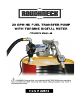
3
Start dispensing into a measuring glass.
Stop dispensing when over 5 liters of volume is
reached, then read out the actual value. The volume
that is displayed on the LCD is the Display Value,
not the Actual Value, which may be slightly higher.
For example, in the figure on the right, the Display
Value is 18.96 while the Actual Value is 20.75.
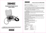
4
Press the MENU key. Keep it pressed until showed
as the right fig., the digit flash in zone, Press the
RESET key to choose the right digit from 0 to 9.
Press the MENU key to go the next digit so that the
Actual Value can be input.
5
Make sure the correction factor is right and then
press the MENU key. Keep it pressed until
calibration is finished and the factor is save. The
meter will then return to standby.
MAINTENANCE
Before any kind of disassembly is carried out, always make sure the machine is stopped, the plug is
disconnected and the pump and the flow meter are emptied. For a better operation, clean up any kind of
debris in the flow meter filter every three months.
The pumps are designed and constructed to require a minimum of maintenance.
On a weekly basis, check that the tubing joints have not loosened, to avoid any leakage.
On a monthly basis, check the pump body and keep it clean of any impurities.
On a monthly basis, check and keep the pump filter clean and any other filters installed.
On a monthly basis, check that the electric power supply cables are in good condition.
Under normal working conditions the noise emission from all models does not exceed the value of 70dB at
a distance of 3 feet from the electric pump.

Page of
MECHANICAL RISKS
Mechanical parts subject to wear and tear
Parts such as blades, bearings, rotors, etc. should be replaced with original spare parts by qualified personal
only or in authorized service centers.
Risks due to extreme temperatures
Make sure the pump works at the ambient temperature ranging from -4°F (-20°C) to 113°F (45°C).
Remember that operating at a very low temperature (about -4°F/ -20°C) can freeze the oil inside the pump.
This situation can cause serious damage to the motor pump unit.
A very high temperature (above 113°F may cause the plastic parts in the unit to expand. The unit should be
placed in a well-ventilated place and protected against the sun.
TROUBLE SHOOTING
Problem
Possible Cause
Corrective Action
Lack of electric power
Check the electrical connections
and the safety systems
Rotor jams
Check for possible damage or
obstruction of the rotating
components.
The motor is not turning
Motor problems
Contact with the service
department
Low level in the suction tank
Refill the tank
Filter clogged
Clean the filter
Excessive suction pressure
Lower the pump with respect to the
level
High loss of head in the circuit
(working with the bypass open)
Use shorter tubing or of greater
diameter
Bypass valve blocked
Dismantle the valve, clean and/or
replace it
Air entering the pump or the
suction tubing
Check the seals of the connections
A narrowing in the suction tubing
Use tubing suitable for working
under suction pressure
Low rotation speed
Check the voltage at the pump.
Adjust the voltage and/or use
cables of greater cross-section
Low or no flow rate
The suction tubing is resting on the
bottom of the tank
Raise the tubing
Cavitation (bubbles) occurring
Reduce suction pressure
Irregular functioning of the bypass
Dispense until the air is purged
from the circuit
Increased pump noise
Air present in the diesel fuel
Verify the suction connections
Leakage from the pump body
Seal damaged
Check and replace the mechanical
seal

Page of
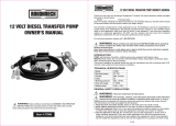
DIAGRAM & PARTS LIST
Part No.
Description
Quantity
1
Nut
4
2
Housing
1
3
Elbow
1
4
Outlet
1
5
Washer
4
6
Screw
4
7
Pump
1
8
Inlet with filter
1
9
Manual Nozzle
1
10
Turbine Digital meter
1
For replacement parts and technical questions, please call 1-800-222-5381.
WARRANTY
One-year limited warranty
Distributed by
Northern Tool + Equipment Co., Inc.
Burnsville, MN 55306
NorthernTool.com
Made in China
/