Lefroy Brooks FH 1148 Installation & Servicing Guide
- Category
- Sanitary ware
- Type
- Installation & Servicing Guide
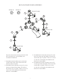
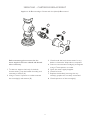
Lefroy Brooks FH 1148 is a deck mounted bath shower mixer with standpipes, suitable for every possible application, type of boiler and water supply pressure. The product is equipped with ceramic cartridges and features a thermostatic mixing valve to restrict the temperature to a safe working maximum. The mixer comes with a hand shower and a hose, and it can be installed with taller standpipes if specified at the point of order. To reduce the height of the standpipes, the bottom of both standpipe tubes can be cut to the same height.
Lefroy Brooks FH 1148 is a deck mounted bath shower mixer with standpipes, suitable for every possible application, type of boiler and water supply pressure. The product is equipped with ceramic cartridges and features a thermostatic mixing valve to restrict the temperature to a safe working maximum. The mixer comes with a hand shower and a hose, and it can be installed with taller standpipes if specified at the point of order. To reduce the height of the standpipes, the bottom of both standpipe tubes can be cut to the same height.


-
 1
1
-
 2
2
-
 3
3
-
 4
4
-
 5
5
-
 6
6
-
 7
7
-
 8
8
-
 9
9
-
 10
10
-
 11
11
-
 12
12
-
 13
13
-
 14
14
-
 15
15
-
 16
16


Lefroy Brooks FH 1148 Installation & Servicing Guide
- Category
- Sanitary ware
- Type
- Installation & Servicing Guide
Lefroy Brooks FH 1148 is a deck mounted bath shower mixer with standpipes, suitable for every possible application, type of boiler and water supply pressure. The product is equipped with ceramic cartridges and features a thermostatic mixing valve to restrict the temperature to a safe working maximum. The mixer comes with a hand shower and a hose, and it can be installed with taller standpipes if specified at the point of order. To reduce the height of the standpipes, the bottom of both standpipe tubes can be cut to the same height.
Ask a question and I''ll find the answer in the document
Finding information in a document is now easier with AI
Related papers
-
Lefroy Brooks TT 2112 Installation & Servicing Guide
-
-
-
-
-
Lefroy Brooks ML 1144 User guide
-
-
-
-
Other documents
-
Duravit WA4210012 Specification Manual
-
-
-
IDEAL STANDARD A7594 Installation guide
-
-
-
Better Bathrooms Deck Bath Mixer User manual
-
Better Bathrooms BeBa 26699 User manual
-
Kohler K-9530-CP Installation guide
-
Kohler 9530-AF Installation guide