

CONTENTS
PAGE NO
fA)
Model
name
comDosmon
of w
8000
sreles i
M)
Descnpt'on
of
v.w
Series
Sewing
Machines
2
(2)
Specifications
2
f3)
Table
Stand
Assemblina
Illustration 3
f4)
Dimensions
of
Motor
Pullev
4
(5)
Filling
and Draining of
Oil,
Replacement
of oi1
FiIter
4
(6)
Assembling
Method
of
Needles
5
(7)
Threading
Method
5
t'8)
Adiustment
of
Feeding
Mecnanism
g
(9)
Height
of
Feed
Dog
g
MO)
Height
of
Needle
Bar
j
(11)
Distance
between
Loooer
and
Needle
8
M2) Adiustment of Clearance from Needle
to
Loooer
Point g
(13)
Adiustment
of
Neeoie
Guard
g
M4)
Ad.iustment
of
Neeoie
Guide
10
M5)
Ad.iustment
of
Loooer
Thread
H
M6)
Timina
of
Looper
Thread
Ad.iusting
Cam
12
(17)
Position of
Needle
Thread
Guide
13
(18)
Adjustment
of
Spreader
Mechanism
13^ 14^
15
From the library of: Superior Sewing Machine & Supply LLC

(A)
MODEL
NAME
COMPOSITION
OF
W8000
SERIES
i FLM ^ I
W-8002-D/yiC
UNDER THREAD CUTTER.
TO
INCLUDE
USAGE
OF
ATTACHMENT,
BINDER,
ETC.
D
FLAT
LOCK.
COLLARETTE (
BINDING
).
ATTACHING
LACE
OR ELASTIC W/O CUTTER.
F
OE
EMK TOP
ELASTIC
METERING
DEVICE
WITH EDGE
CUTTER.
EMK-E ELECTRONIC CONTROLLED TOP
ELASTIC
METERING
DEVICE
WITH EDGE
CUTTER.
MC-12A
AUTOMATIC REAR
TAPE
CUTTER.
C-11
CLINTON
CHAIN
CUTTER.
S
SHELL
STITCHING.
'0
INDICATE
NUMBER
OF
NEEDLES
:
01
02
03
04
42
42-1
1
NEEDLE.
2
NEEDLES.
3
NEEDLES.
4
NEEDLES.
2
NEEDLES.
3
NEEDLES.
TO
INDICATE
STITCHING
WAY :
70
BOTTOM
COVERING.
30
'CP
& BOTTOM
COVERING.
71
BOTTOM
COVERING.
(LATEST
MODEL
NO).
31
'OP
&
BOTTOM
COVERING.
(LATEST
MODEL
NO)
SYMBOL
OF
MACHINE
SERIES.
(FLAT
BED
MACHINE)
BOTTOM
COVERING.
TOP
& BOTTOM
COVERING.
-1
-
From the library of: Superior Sewing Machine & Supply LLC

(1) Description of
V.W
Series
Sewing
Machines
No.
of
Needles
Needle
gauge
Height
of
needle
bar
Distance
between
looper
and
needle
O
<•
1/8
11
4
5/32
10.3
1 4
3/16
9.5
4
7/32
8.4
4
1/4
7.5
4
3
7/32
8.4
4
1/4
7.5
Table
1
(2)
Specifications
Type
:Ultra-high sceea
flat
bed
2 or 3 needle
sewing
machine
Numoer
of
stitches
: 2
to
u
oer
one inch
(25.4
mm)
Number
of
needles
: 2
cr
3
Type
of
needle
:
UY-'<2S
GAS
JtTO
to
«90
Needle
bar
stroke
:
2:
Feeding
Mechanism :
Differential
feed
Differential
ratio
aclustment ; Lever type
Lubrication
Svstom
:
-uily
autcr.atic lucr*lation system
Maximum
soeeo
:
5.500
stitches
a
minute
-2-
From the library of: Superior Sewing Machine & Supply LLC


(4)
Dimensions
of
Motor
Pullev
The
rotation
direction
is
counterclockwise
viewing
the
pulley.
Select
a
pulley
so
that
the
maximum
speed
shall
be
4,500
rpm
and
operate
the
machine
at
speed
below
4,500
rpm
when
polyester
spun
threads are
used
for
the
accuracy
of
the
number
of
stitches.
Machine
speed
Outside diameter of motor pulley
60
Hz
50
Hz
•5.500
j
dia
95
dia
110
5,000
35
100
4,500
1
75
90
4.000
65
80
Table
2
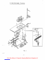
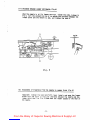
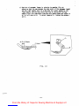
(5)
Filling
and
Draining
of Oil,
and
Replacement
of oil
filter
(Fig
2)
Recommenoed
lubricating
oil
is
"Tellesso
33".
1)
Remove
the
siphon
case A
and
fill
oil
from
the
filler
port
till
the
oil level reaches tr.e
marking
line Bof the
oil
gauge.
Be
sure
that
-he
oil
level is
oetween
the
marking
lines 8
and
D,
each time before
startina
operation.
2)
Draining
oi1
CFig 2-•)
Remove
the
screw
E
ana
drain oil
from
the
oil
pan.
Exchange
the
entire
used oi1 wirr,
new
oil
in one
month
after
the
operation of
the
machine
is
started,
and
every
six
months
after
that.
31
Filter
(Fig
2-2;
Check
the
filter
10 cavs
after
the
operation
of
the
machine
is
startea.
ana
everv
one month
after
that.
Blow
dirt
off
the
filter
with compresseo
air
or replaced the
filter
if
clogged with
dirt.
Pig.
2-1
-4-
From the library of: Superior Sewing Machine & Supply LLC

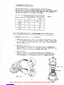
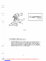
(5)
Assembling Method
of
Needles
Use
the
needles
UY
128
GAS
870
to
890. Loosen
the
needle
fastening
screws A and
reolace
the
needles.
Set
the
neeoles
so
that
the
grooves
of
the
needles
shall
be
just
on
the
rear
side.
^
L)
Fig.
3
C7)
Threading
Method
(Fig
4)
Pass
through
both
uoper
ana
lower
threacs
correctly
by
referring
to
Fig
4.
Adjust
the
tsns-cn
cf
thread
with
the
thread
tension
nut
(N).
Adjust
so
that
satisfactory
stitching
can
be
obtained
at
a
tension
of
threaos
as
low
as
cracticaole.
gi
Fig.
4
-5-
From the library of: Superior Sewing Machine & Supply LLC

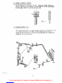
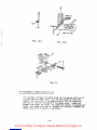
(8)
Adjustment
of
Feeding
Mechanism
(Fig
5)
a) Adjustment
of
feeding
loosen
the
lock
C
(left-hand
threads)
and
turn
the
adjusting
screw
N
to
an
adeouate
feed.
The
feed
is
reduced
bv
turning
the
screw
CiOCkwIse
and
increased
by
turning counterciockwise.
b) Adjustment
of
differential
ratio
Loosen
the
nut
I
and
raise
the
connecting
crank
Hfor
increasing
the
differential
ratio,
and
lower
the crank
for
decreasing the
differential
ratio.
Fig.
5
(Note)
Must
cnecK
tr.e position of the needle guard in
relation
to
the
neeale
wr.en
tr.e
fesoing
distance
is
adjusted.
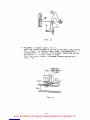
(9)
Height
of
feed dog
(Fig
6)
he oi.aridard neignt ct the "eso
dog
is
0.8mm
to
l.2mm
above
the
surface
ZT
tne
neeole
Diate
wnen
tne
rsea
dog
is
at
its
highest
position.
To
ad
lust the r.eignt, 'ocsen tne screws A
and
B,
and
set
the heights of
the
main
feed dcg
ano
the
diffsrsntial
feed
dog
as
shown
in g Fig 6.
0,8-1.2imn
Meedle
platQ
-6-
Fig.
6
From the library of: Superior Sewing Machine & Supply LLC

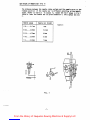
00)
Height
of
Needle
Bar
(Fig
7)
The
distance
between
the needle
plate
surface and the needle point
at
the
highest
position
of
the
needle
bar
is
different
according
to
the
needle
gauge. (Refer
to
Table 3)
To
adjust
it,
loosen the nut F
shown
in Fig 7,
raise
or
lower
the
needle
bar
to
given
dimension Y, and
tighten
the
nut
F.
Needle
gauge
Needle
bar
height
1/8
3.17mm
11mm
5/32...
.3.96inm
10.3mm
3/16....4.76mm
9.5mm
7/32....
5.56mm
8.4mm
1/4
6.35mm
7.6mm
7
-7-
Table
3
From the library of: Superior Sewing Machine & Supply LLC

(11)
Distance
between
Looper
and
Needle
(Fig
8)
E
When
the
needle
is at its
lowest
position,
loosen
the
nuts
A
shown
in
Fig
8,
turn
the
connecting
rod
8, to
adjust
the
distance
between
the
looper
point
and
the
needle
to
4nim,
and
tighten the
nuts
A.
Am/in
Fig.
8
(12.)
Adjustment
of Clearance
from
the needle to
Looper
Point (Fig 9)
TemporaTilv
tighten
the back-and-forth lever loosely and
move
the
looper
holder
back and
forth
so
that
the
clearance
between
the
needle and
the
loooer point
shall
be C to
0.05mm
when
the looper passes by
the
rear
of
the
needle.
-8-
From the library of: Superior Sewing Machine & Supply LLC

Fig.
9
(15) Adjustment
of
Needle Guaro (Fig 10)
The
needle should
ccme
into contact lightly with the needle
guard
at
a
point of
O.Smm
from
the point of the
needle
when
the point of the
looper
is at the rear
middle
of the right needle.
Adjust
the
back-and-
forth position
by
loosening
the fastening
screw
0 in
Fig
11
and
the
height of the needle
guard
by
loosening
screws
A in Fig
11
so that the
dimension shown in Fig
ic-b
chall
be
O.S.'wn
-9-
From the library of: Superior Sewing Machine & Supply LLC

1
Or8m/raf
Pig.
10-a
Pig.
10-b
D
Pig.
ll
(14-)
Adjustment
of
Needle Guide fFig
121
The
clearance
F between
tne
needle
guide
and
the
needles
shall
be
0.2
-G
0.5mm
when
the
loooer
point
is
at
the
rear
middle
of
the
right
needle. Set the neignt cf the needle guide so
that
the needle'eye
shall
be in
line
with
the
middle
of
the
needle guide. Loosen
the
screws E ana aa.iust
the
neight,
and loosen
the
screws E and
adjust
the
height,
and
loosen
the
screws G. Whereby
the
clearance
Fbetween
the
needle
guide
ana
the
needles
is
adjustable.
-10-
From the library of: Superior Sewing Machine & Supply LLC

?ig.
12
(15) Adjustment of
Looper
Thread (Fig 13)
a)
Adjust
the
clearance
between
the
looper
thread retaining finger B
and the bracket E to 6 to
7mni
(by loosening the screw F)
b)
Adjust
the position of the
looper
thread
guide
by
loosening
the
screw G so
that
the thread guide hole A
shown
in Fig
13
shall
be on
the
center
line
of
the
main
shaft.
-11-
From the library of: Superior Sewing Machine & Supply LLC


(17)
Position
of
Needle Thread Guide
(Fig
15)
Loosen
the screw C
shown
in Fig
15
and
adjust
the
position
of
the
needle thread guide so
that
the top face of the thread guide
(A)
shall
be
lined
with
the
'0'
graduation
of
the
scale.
Fig.
1
(18)
Adjustment
of
Spreader
Mechanism
a)
Loosen
the screw 0
and
aolust the ocsition of
the
spreader thread
guide C
shown
in Fig
16
so
that
the
thread guide hole
shall
be lined
with
the
graduation
'3'
of
the
scale.
-
13-
From the library of: Superior Sewing Machine & Supply LLC

Fig.
16
b) Adjustment
of
screaaer
looper
( Fig 17)
Adjust
the
distance
between
the
too
face
of
the
needle
plate
and
the
lower
surface
c* the
soreader
looper
to
8mm.
Also
adjust
the
distance
between tr.e
underside
of
the
spreader
thread
guide
and
the
too
surface
zf
f.e
soreacer
locper
to
0.5mm.
Adjust
the
distance
between
the
spreader
thread
guide
and
the
*L'
cuida
to
1mm.
0,5a/m
I m
u ^ ^ ^
j-rrr
Fig.
17
-
14-
From the library of: Superior Sewing Machine & Supply LLC

c)
Position
of
spreader
looper
In
relation
to
needles
(F1g 18)
Adjust
so
that
the
gap between
the
hook
point
of
the
spreader
looper
and
the
right
needle
shall
be
O.Smm
when
the
looper
passes
by
the
right
needle,
and
the
hook
point
shall
be
at
the
point
A on
the
needle
line
6
to
e.Smm
apart
from
the-left
needle
when
the
looper
Is
at
Its
left
dead
point.
To
adjust
temporarily
tighten
the
screws
L
and
K.
A 6 -
6,5m/m
0,
5tn/m;
/•;/• i
Fig.
18
- 1
5-
From the library of: Superior Sewing Machine & Supply LLC

'A
f
MORIMOTO
MFG.
CO..
LTD.
MAIN
FACTORY
180,
Suna
Shijonawate-citv,
Osaka
575,
Jaoan
Tel:
(0720)
77-1221
Telex:
5349134
KSPCAL-J
Fax:
(0720)
78-9649
TOKYO
OFRCE
5-16-7,
Kohtobashi
Sumida-ku,
Tokyo 130,
Japan
Tel:
(03)
635-5121
Fax:
(03)
635-5123
OKAYAMA
OFFICE
Village Okuda IF, 24-19, Gkuaa-Honmacni Okavama-citv 700,
Japan
Tel:
(0862)
32-9120
Fax:
(0862)
22-8292
KANSAI
SPECIAL
U.S.A.
CORP.
640
Gotham
Parkway
Carlstadt
N.J.
07072
U.S.A.
Tel:
(201)
460-0350
Telex:
219449
(KSPCUR)
Fax:
(201)
460-1633
MORIMOTO
MFG.
(H.K.) LTD.
203-207 G/F., Lai Chi
Kok
Road, Sham Shui Po, Kowloon, Hong Kong
Tel:
3-918357-9
Telex:
31167
MORHK
NX
Fax;
3-7891707
MORIMOTO
MFG.
(H.K.) LTD.
SINGAPORE
REP.
OFFICE
1, Marine Parade Central. #07-08/09 Parkway Builders' Centre Singapore 1544.
Tel:
65-3457576/3448477
Telex:
RS
25138
MMHKS
Fax:
65-3449603
KANSAI
SPECIAL
Ml
EUROPE
G.M.B.H.
Wahler
Strasse
37
4000
Dusseldorf,
30
W,
GERMANY
Tel:
0211-658020
Telex:
8586555
KSWGD
Fax:
0211-6581529
From the library of: Superior Sewing Machine & Supply LLC
-
 1
1
-
 2
2
-
 3
3
-
 4
4
-
 5
5
-
 6
6
-
 7
7
-
 8
8
-
 9
9
-
 10
10
-
 11
11
-
 12
12
-
 13
13
-
 14
14
-
 15
15
-
 16
16
-
 17
17
-
 18
18


Ask a question and I''ll find the answer in the document
Finding information in a document is now easier with AI
Other documents
-
Husqvarna Huskylock 900 Owner's manual
-
Siruba C858KD Instruction book
-
UnionSpecial 39500AC Instructions For Adjusting And Operating
-
Sears 385.16631 User manual
-
 Rimoldi 264 Instruction Handbook Manual
-
 kansai MC30 Operating instructions
-
White 1300DE User manual
-
 Kondo Yamato DCZ-367Y Instructions And Operating Manual
-
 kansai A-1001P Instructional Manual
-
SINGER 14SH754 Owner's manual


