
Revision 1.2 (12/12/2017)
User Manual
EC301
Potentiostat / Galvanostat
Stanford Research Systems

Certification
Stanford Research Systems certifies that this product met its published specifications at the time of shipment.
Warranty
This Stanford Research Systems product is warranted against defects in materials and workmanship for a
period of one (1) year from the date of shipment.
Service
For warranty service or repair, this product must be returned to a Stanford Research Systems authorized
service facility. Contact Stanford Research Systems or an authorized representative before returning this
product for repair.
Information in this document is subject to change without notice.
Copyright ©Stanford Research Systems, Inc., 2012 — 2017. All rights reserved.
Stanford Research Systems, Inc.
1290–D Reamwood Avenue
Sunnyvale, CA 94089 USA
Phone: (408) 744-9040 •Fax: (408) 744-9049
www.thinkSRS.com •e-mail: info@thinkSRS.com
Printed in U.S.A. Document number 9-01712-903
2EC301 Potentiostat/Galvanostat/ZRA

Contents
1 General information 6
1.1 Safety and preparation for use . . . . . . . . . . . . . . . . . . . . . . . . . . . . . . . . . . . 6
1.2 Unpacking . . . . . . . . . . . . . . . . . . . . . . . . . . . . . . . . . . . . . . . . . . . . . . 7
1.2.1 Standard equipment . . . . . . . . . . . . . . . . . . . . . . . . . . . . . . . . . . . . 7
1.2.2 Accessories . . . . . . . . . . . . . . . . . . . . . . . . . . . . . . . . . . . . . . . . . 7
1.2.3 Optional equipment . . . . . . . . . . . . . . . . . . . . . . . . . . . . . . . . . . . . 7
1.3 Symbols you may find on SRS products . . . . . . . . . . . . . . . . . . . . . . . . . . . . . . 8
1.4 Specifications . . . . . . . . . . . . . . . . . . . . . . . . . . . . . . . . . . . . . . . . . . . . 9
1.5 Serial number and firmware revision . . . . . . . . . . . . . . . . . . . . . . . . . . . . . . . . 19
2 EC301 basics 20
2.1 Software . . . . . . . . . . . . . . . . . . . . . . . . . . . . . . . . . . . . . . . . . . . . . . . 20
2.2 Functional block diagram . . . . . . . . . . . . . . . . . . . . . . . . . . . . . . . . . . . . . . 20
2.3 Polarity convention . . . . . . . . . . . . . . . . . . . . . . . . . . . . . . . . . . . . . . . . . 22
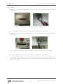
2.4 Connecting the EC19 to the EC301 . . . . . . . . . . . . . . . . . . . . . . . . . . . . . . . . 22
2.4.1 Necessary Items . . . . . . . . . . . . . . . . . . . . . . . . . . . . . . . . . . . . . . 22
2.4.2 Steps . . . . . . . . . . . . . . . . . . . . . . . . . . . . . . . . . . . . . . . . . . . . 23
3 Operation 24
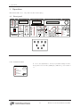
3.1 Front panel . . . . . . . . . . . . . . . . . . . . . . . . . . . . . . . . . . . . . . . . . . . . . 24
3.1.1 Power-on reset . . . . . . . . . . . . . . . . . . . . . . . . . . . . . . . . . . . . . . . 24
3.1.2 Bandwidth limit . . . . . . . . . . . . . . . . . . . . . . . . . . . . . . . . . . . . . . 25
3.1.3 CE limit . . . . . . . . . . . . . . . . . . . . . . . . . . . . . . . . . . . . . . . . . . 25
3.1.4 Cell . . . . . . . . . . . . . . . . . . . . . . . . . . . . . . . . . . . . . . . . . . . . . 25
3.1.5 External electrometer . . . . . . . . . . . . . . . . . . . . . . . . . . . . . . . . . . . 26
3.1.6 Voltage . . . . . . . . . . . . . . . . . . . . . . . . . . . . . . . . . . . . . . . . . . . 26
3.1.7 Current . . . . . . . . . . . . . . . . . . . . . . . . . . . . . . . . . . . . . . . . . . . 26
3.1.8 Mode . . . . . . . . . . . . . . . . . . . . . . . . . . . . . . . . . . . . . . . . . . . . 27
3.1.9 Rotating electrode . . . . . . . . . . . . . . . . . . . . . . . . . . . . . . . . . . . . . 27
3.1.10 Analog output . . . . . . . . . . . . . . . . . . . . . . . . . . . . . . . . . . . . . . . 28
3.1.11 Current range . . . . . . . . . . . . . . . . . . . . . . . . . . . . . . . . . . . . . . . 29
3.1.12 IR compensation . . . . . . . . . . . . . . . . . . . . . . . . . . . . . . . . . . . . . . 30
3.1.13 External input . . . . . . . . . . . . . . . . . . . . . . . . . . . . . . . . . . . . . . . 31
3.1.14 Measurement setup/control . . . . . . . . . . . . . . . . . . . . . . . . . . . . . . . . 33
3.1.15 Knob . . . . . . . . . . . . . . . . . . . . . . . . . . . . . . . . . . . . . . . . . . . . 33
3.1.16 Configure . . . . . . . . . . . . . . . . . . . . . . . . . . . . . . . . . . . . . . . . . . 34
3.1.17 Remote status . . . . . . . . . . . . . . . . . . . . . . . . . . . . . . . . . . . . . . . 35
3.2 Rear panel . . . . . . . . . . . . . . . . . . . . . . . . . . . . . . . . . . . . . . . . . . . . . . 36
3.2.1 Power entry . . . . . . . . . . . . . . . . . . . . . . . . . . . . . . . . . . . . . . . . 36
3.2.2 GPIB interface . . . . . . . . . . . . . . . . . . . . . . . . . . . . . . . . . . . . . . . 36
3.2.3 Ethernet interface . . . . . . . . . . . . . . . . . . . . . . . . . . . . . . . . . . . . . 37
3.2.4 Current interrupt synchronization . . . . . . . . . . . . . . . . . . . . . . . . . . . . 37
3.2.5 Timebase synchronization input . . . . . . . . . . . . . . . . . . . . . . . . . . . . . 37
3.2.6 Scan trigger input . . . . . . . . . . . . . . . . . . . . . . . . . . . . . . . . . . . . . 38
3.2.7 Program E/I output . . . . . . . . . . . . . . . . . . . . . . . . . . . . . . . . . . . 40
3.2.8 Scan synchronization output . . . . . . . . . . . . . . . . . . . . . . . . . . . . . . . 41
3.2.9 Auxiliary ADC inputs (1-3) . . . . . . . . . . . . . . . . . . . . . . . . . . . . . . . 42
3.2.10 Resistance temperature detector (RTD) input . . . . . . . . . . . . . . . . . . . . . 43
3.2.11 Grounding posts . . . . . . . . . . . . . . . . . . . . . . . . . . . . . . . . . . . . . . 44
3.2.12 Raw analog outputs . . . . . . . . . . . . . . . . . . . . . . . . . . . . . . . . . . . . 45
3.2.13 CE monitor . . . . . . . . . . . . . . . . . . . . . . . . . . . . . . . . . . . . . . . . 46
3.2.14 Synchronous ADC input . . . . . . . . . . . . . . . . . . . . . . . . . . . . . . . . . 47
3

Contents
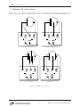
4 Making cell connections 48
4.1 Floating operation . . . . . . . . . . . . . . . . . . . . . . . . . . . . . . . . . . . . . . . . . 49
4.1.1 Overview . . . . . . . . . . . . . . . . . . . . . . . . . . . . . . . . . . . . . . . . . . 49
4.1.2 Grounded Working Electrode . . . . . . . . . . . . . . . . . . . . . . . . . . . . . . . 50
4.1.3 Grounded Counter Electrode . . . . . . . . . . . . . . . . . . . . . . . . . . . . . . . 50
4.2 Working with grounded electrodes . . . . . . . . . . . . . . . . . . . . . . . . . . . . . . . . . 51
5 Performing scans using the front panel 54
5.1 Setting scan parameters – potentiostat mode . . . . . . . . . . . . . . . . . . . . . . . . . . . 54
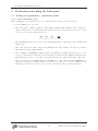
5.1.1 Cyclic voltammetry (CV) . . . . . . . . . . . . . . . . . . . . . . . . . . . . . . . . . 54
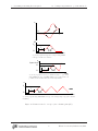
5.1.2 Linear sweep voltammetry (LSV) . . . . . . . . . . . . . . . . . . . . . . . . . . . . 56
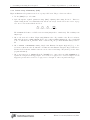
5.1.3 Steps . . . . . . . . . . . . . . . . . . . . . . . . . . . . . . . . . . . . . . . . . . . . 58
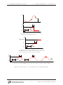
5.1.4 Holds . . . . . . . . . . . . . . . . . . . . . . . . . . . . . . . . . . . . . . . . . . . . 60
5.2 Setting scan parameters – galvanostat mode . . . . . . . . . . . . . . . . . . . . . . . . . . . 61
5.2.1 Cyclic current ramp . . . . . . . . . . . . . . . . . . . . . . . . . . . . . . . . . . . . 61
5.2.2 Linear current ramp . . . . . . . . . . . . . . . . . . . . . . . . . . . . . . . . . . . . 62
5.2.3 Current step . . . . . . . . . . . . . . . . . . . . . . . . . . . . . . . . . . . . . . . . 63
5.2.4 Current hold . . . . . . . . . . . . . . . . . . . . . . . . . . . . . . . . . . . . . . . . 64
5.3 Basic scan controls . . . . . . . . . . . . . . . . . . . . . . . . . . . . . . . . . . . . . . . . . 65
5.4 Triggering scans . . . . . . . . . . . . . . . . . . . . . . . . . . . . . . . . . . . . . . . . . . . 65
5.4.1 Triggering a scan from the front panel . . . . . . . . . . . . . . . . . . . . . . . . . . 65
5.4.2 Triggering a scan with the scan trigger input . . . . . . . . . . . . . . . . . . . . . . 65
5.4.3 Triggering a scan from the remote interface . . . . . . . . . . . . . . . . . . . . . . . 65
5.5 Setting the end of scan condition . . . . . . . . . . . . . . . . . . . . . . . . . . . . . . . . . 65
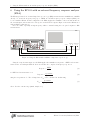
6 Using the EC301 with an external frequency response analyzer (FRA) 67
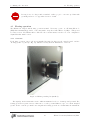
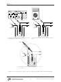
7 Boosted current operation 68
7.1 System installation . . . . . . . . . . . . . . . . . . . . . . . . . . . . . . . . . . . . . . . . . 68
7.2 Ventilation and cooling . . . . . . . . . . . . . . . . . . . . . . . . . . . . . . . . . . . . . . . 69
7.3 Entering boosted operation . . . . . . . . . . . . . . . . . . . . . . . . . . . . . . . . . . . . . 70
7.4 Current interrupt under boosted operation . . . . . . . . . . . . . . . . . . . . . . . . . . . . 71
7.5 Bandwidth limitation under boosted operation . . . . . . . . . . . . . . . . . . . . . . . . . . 72
7.6 Returning to normal operation . . . . . . . . . . . . . . . . . . . . . . . . . . . . . . . . . . . 72
7.7 Initial booster checkout . . . . . . . . . . . . . . . . . . . . . . . . . . . . . . . . . . . . . . . 72
7.7.1 Open circuit test . . . . . . . . . . . . . . . . . . . . . . . . . . . . . . . . . . . . . . 72
7.7.2 Short circuit test . . . . . . . . . . . . . . . . . . . . . . . . . . . . . . . . . . . . . . 73
8 Remote programming 75
8.1 Command syntax . . . . . . . . . . . . . . . . . . . . . . . . . . . . . . . . . . . . . . . . . . 75
8.2 Argument formats . . . . . . . . . . . . . . . . . . . . . . . . . . . . . . . . . . . . . . . . . . 75
8.3 Detailed command list . . . . . . . . . . . . . . . . . . . . . . . . . . . . . . . . . . . . . . . 76
8.3.1 Firmware and hardware revisions . . . . . . . . . . . . . . . . . . . . . . . . . . . . 76
8.3.2 Program E/I setup (with external input) . . . . . . . . . . . . . . . . . . . . . . . . 76
8.3.3 Control loop commands . . . . . . . . . . . . . . . . . . . . . . . . . . . . . . . . . . 79
8.3.4 Cell switch . . . . . . . . . . . . . . . . . . . . . . . . . . . . . . . . . . . . . . . . . 81
8.3.5 IR compensation . . . . . . . . . . . . . . . . . . . . . . . . . . . . . . . . . . . . . . 82
8.3.6 Scan trigger commands . . . . . . . . . . . . . . . . . . . . . . . . . . . . . . . . . . 84
8.3.7 Rotating working electrode commands . . . . . . . . . . . . . . . . . . . . . . . . . 85
8.3.8 Analog output commands . . . . . . . . . . . . . . . . . . . . . . . . . . . . . . . . . 86
8.3.9 Voltage (E) measurement setup . . . . . . . . . . . . . . . . . . . . . . . . . . . . . 88
8.3.10 Current (I) measurement setup . . . . . . . . . . . . . . . . . . . . . . . . . . . . . 89
8.3.11 Reading single measurement results . . . . . . . . . . . . . . . . . . . . . . . . . . . 91
8.3.12 Streaming data . . . . . . . . . . . . . . . . . . . . . . . . . . . . . . . . . . . . . . 93
8.3.13 Remote interface commands . . . . . . . . . . . . . . . . . . . . . . . . . . . . . . . 97
4EC301 Potentiostat/Galvanostat/ZRA

Contents
8.3.14 Timebase commands . . . . . . . . . . . . . . . . . . . . . . . . . . . . . . . . . . . 100
8.3.15 Status reporting commands . . . . . . . . . . . . . . . . . . . . . . . . . . . . . . . . 101
8.3.16 Pulsed waveform generation commands . . . . . . . . . . . . . . . . . . . . . . . . . 111
8.3.17 Ramp generation commands . . . . . . . . . . . . . . . . . . . . . . . . . . . . . . . 117
8.3.18 Arbitrary waveform generation commands . . . . . . . . . . . . . . . . . . . . . . . 122
8.3.19 Reading temperature measurements . . . . . . . . . . . . . . . . . . . . . . . . . . . 127
8.3.20 Booster operation commands . . . . . . . . . . . . . . . . . . . . . . . . . . . . . . . 128
8.4 Programming examples . . . . . . . . . . . . . . . . . . . . . . . . . . . . . . . . . . . . . . . 129
8.4.1 Normal pulse . . . . . . . . . . . . . . . . . . . . . . . . . . . . . . . . . . . . . . . . 129
8.4.2 Cyclic voltammetry . . . . . . . . . . . . . . . . . . . . . . . . . . . . . . . . . . . . 130
8.4.3 Current interrupt IR compensation . . . . . . . . . . . . . . . . . . . . . . . . . . . 131
8.4.4 Arbitrary waveform . . . . . . . . . . . . . . . . . . . . . . . . . . . . . . . . . . . . 132
Bibliography 133
A Measuring cell voltages at the cell 134
B Pinouts 136
B.1 Cell interface (25 pins) . . . . . . . . . . . . . . . . . . . . . . . . . . . . . . . . . . . . . . . 136
B.2 RTD interface (5 pins) . . . . . . . . . . . . . . . . . . . . . . . . . . . . . . . . . . . . . . . 136
C Major symbols and abbreviations 138
Alphabetical command index 139
5EC301 Potentiostat/Galvanostat/ZRA

1 General information
1 General information
1.1 Safety and preparation for use
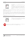
Warning
Dangerous voltages, capable of causing injury or death, are present in this instrument. Use
extreme caution whenever the instrument covers are removed. Do not remove the covers while
the unit is plugged into a live outlet.
Line fuse
Verify that the correct line fuse(s) are installed before connecting the line cord. Fuse size is 3AB/3AG
“slo-blo” (φ6.3×32 mm). For 100 V/120 V, use a single 3 A fuse; for 220 V/240 V, use two 1.5 A fuses.
Line cord
The EC301 has a detachable, three-wire power cord for connection to the power source and to a protective
ground. The exposed metal parts of the instrument are connected to the outlet ground to protect against
electrical shock. Always use an outlet which has a properly connected protective ground.
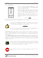
Service
Do not attempt to service or adjust this instrument unless another person, capable of providing first aid or
resuscitation, is present.
Do not install substitute parts or perform any unauthorized modification to this instrument. Contact the
factory for instructions on how to return the instrument for authorized service and adjustment.
6EC301 Potentiostat/Galvanostat/ZRA

1 General information 1.2 Unpacking
1.2 Unpacking
The following lists describe the standard and optional equipment supplied with the EC301. Open the
box(es) and inspect all equipment and components, comparing the contents against your original order and
the checklists below. Report any discrepancies, or any shipping damage, to Stanford Research Systems
immediately.
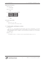
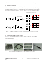
1.2.1 Standard equipment
1. EC301 main unit
2. EC19
3. EC19 terminal cables (6 color coded)
4. Alligator clips (6)
5. Color coded boots for alligator clips (6)
6. Umbilical cable
7. Test board
8. RTD connector
9. This manual
Note: the SRSLab software is included free of charge as a download from the SRS web site, www.thinkSRS.com.
1.2.2 Accessories
1. Replacement terminal cables / clips / boots (order O100CAB)
2. RTD probe (order O100RTD)
3. Rack mount kit (order O301RM)
4. Replacement manual (order M301)
1.2.3 Optional equipment
1. 5 Amp current booster (orderO100BST)
2. 10 Amp current booster (order O200BST)
3. 20 Amp current booster (order O400BST)
4. Quartz crystal microbalance (order QCM200)
7EC301 Potentiostat/Galvanostat/ZRA

1 General information 1.3 Symbols you may find on SRS products
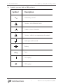
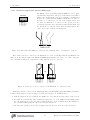
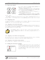
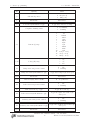
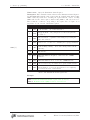
1.3 Symbols you may find on SRS products
Symbol Description
Alternating current
Caution - risk of electric shock
Frame or chassis terminal
Caution - refer to accompanying documents
Earth (ground) terminal
Battery
Fuse
On (supply)
Off (supply)
8EC301 Potentiostat/Galvanostat/ZRA

1 General information 1.4 Specifications
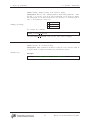
1.4 Specifications
Voltage and current measurement accuracy
•Voltage measurement accuracy
±0.2% of reading (VRE −VWE SENSE)±5mV
•Current measurement accuracy, 1 A range
±0.5% of reading (IWE)±0.2% of range
•Current measurement accuracy, other ranges
±0.2% of reading (IWE)±0.2% of range
•Power amplifier
–Compliance voltage
≥ ±30V full compliance
–Maximum output current
≥ ±1A
–Slew rate (power amplifier in isolation)
≥10V/µs
–Output short-circuit protected
9EC301 Potentiostat/Galvanostat/ZRA

1 General information 1.4 Specifications
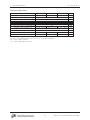
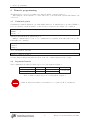
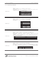
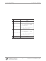
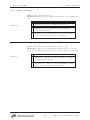
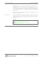
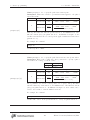
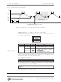
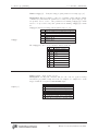
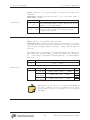
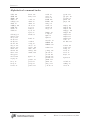
Boosted operation
Option O100BST O200BST O400BST units
Maximum DC Current ±5±10 ±20 Amps
Max. system compliance voltage ±20 V
Applied potential accuracy 0.5% of reading ±5 mV
Current measurement accuracy 1% of reading ±3 mA
Current measurement rise time(1) 45 (at ±2.5 V) 40 (at ±5 V) 40 (at ±10 V) µs
Potentiostatic analog bandwidth (2) 10 kHz
Applied voltage risetime (1) 45 (at ±2.5 V) 40 (at ±5 V) 35 (at ±10 V) µs
Applied current accuracy 0.5% of reading ±3 mA
Measured potential accuracy 0.2% of reading ±5 mV
Galvanostatic analog bandwidth (3) 3 3 1.25 kHz
Applied current risetime (1) 50 (at ±2.5 V) 100 (at ±5 V) 200(at ±10 V) µs
Notes
(1) 10% – 90%, 1 kHz square wave, 0.5 Ω load, at specified amplitude.
(2) −3 dB, 1 Vrms, 1 Ω load.
(3) −3 dB, 1 Amp rms, 0.5 Ω load.
10 EC301 Potentiostat/Galvanostat/ZRA

1 General information 1.4 Specifications
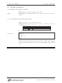
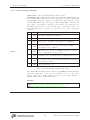
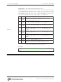
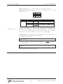
Potentiostat mode
•Applied potential accuracy:
Potential versus reference within Accuracy
±5V ±0.2% of setting ±5mV
±10V ±0.5% of setting ±5mV
±15V ±1% of setting ±5mV
•Applied potential resolution:
Mode Resolution
General (potential set with thumbwheel or remote interface) 500µV
Performing an automatic scan (CV or LSV) 200µV
•Noise and ripple
<20µVrms (1Hz →10kHz)
•Applied E range
±15V versus reference (|CE|<30V versus signal ground)
11 EC301 Potentiostat/Galvanostat/ZRA

1 General information 1.4 Specifications
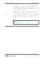
Galvanostat mode
•Applied current accuracy:
±0.5% of setting ±0.2% of current range, 1 A range
±0.2% of setting ±0.2% of current range, all other ranges
ZRA mode
•Voltage offset
CE sense and WE sense electrodes held within 5 mV of each other
•Output current
1 A range: −1 A min, +1 A max
All other ranges: −2×full scale min, +2×full scale max
12 EC301 Potentiostat/Galvanostat/ZRA

1 General information 1.4 Specifications
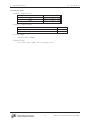
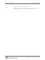
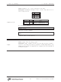
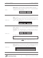
General control loop
•Bandwidth control
Bandwidth limits
10Hz, 100Hz, 1kHz, 10kHz, 100kHz, >1MHz
(10kΩ resistive load, <100µA output cur-
rent)
•Compliance limiting
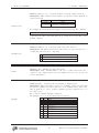
Voltage limit accuracy
Cell current ICEAccuracy
≤10mA ±250 mV
≤1A ±1V
13 EC301 Potentiostat/Galvanostat/ZRA

1 General information 1.4 Specifications
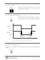
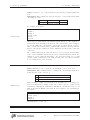
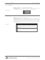
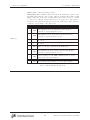
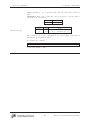
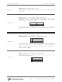
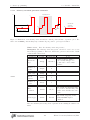
IR compensation
•Current interrupt
Switching time (on →off) <5µs (1 kΩ resistive load)
Interrupt time 100µs→1s
Interrupt frequency 0.1 Hz →300 Hz
•Positive feedback
Range
Irange Ru
boosted (5 A, 10 A, 20 A) 0 →0.3 Ω
1 A 0 →3 Ω
100 mA 0 →30 Ω
10 mA 0 →300 Ω
1 mA 0 →3 kΩ
100 µA 0 →30 kΩ
10 µA 0 →300 kΩ
1µA 0 →3 MΩ
100 nA 0 →30 MΩ
10 nA 0 →300 MΩ
1 nA 0 →3 GΩ
Resolution 1 mΩ for 1A range
1 MΩ for 1nA range
14 EC301 Potentiostat/Galvanostat/ZRA

1 General information 1.4 Specifications
General system
•Remote interfaces
LAN (10/100 base-T Ethernet)
GPIB (IEEE-488)
•Dimensions (W ×H×D)
–Main box
17 ×18.5 ×5.25 inches
–External box
3.25 ×4.75 ×2.5 inches
–Umbilical
36 inches
–Weight
–Power
•RTD measurement
–Temperature sensor
User supplied 100Ω Pt RTD, α= 0.00385 Ω/Ω/℃
–Range
−100 ℃to +200 ℃
–Resistance measurement accuracy
±0.3 Ω
15 EC301 Potentiostat/Galvanostat/ZRA

1 General information 1.4 Specifications
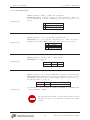
Front panel connectors
•External input
±15V analog input in potentiostat mode, ±2V in galvanostat mode
Input impedance: 10kΩ k50pF
•Rotating electrode output BNC
0→10V analog output
Accuracy: ±1% of setting ±5mV
Output impedance: 10Ω
10mA max output current
•Voltage (E) output BNC
±15V analog output
Accuracy: ±0.2% of VRE −VWE Sense ±5 mV
Output impedance: 50Ω
10mA max output current
•Current (I) output BNC
±2V analog input
Accuracy: IWE within ±0.5% of (VBNC ×Irange)±0.2% ×Irange, 1 A range
Accuracy: IWE within ±0.2% of (VBNC ×Irange)±0.2% ×Irange, other ranges
Output impedance: 50Ω
10mA max output current
16 EC301 Potentiostat/Galvanostat/ZRA

1 General information 1.4 Specifications
Rear panel connectors
•Timebase input BNC
Frequency: 10MHz
Level: 1Vpp (nominal)
•TTL measurement synchronization BNCs
Current interrupt and scan synchronization outputs, scan trigger input
•Program E/I output BNC
±15V analog output
Accuracy: ±0.2% of total program voltage (internal sources + external input) ±5 mV
Output impedance: 10Ω
10mA max output current
•Auxiliary ADC input BNCs
Three ±10V analog to digital inputs
input impedance: 100kΩ
1mV resolution
•Signal / floating ground banana jacks
Signal ground ohmically connected to chassis ground
Floating ground can float ±8 V relative to signal ground
Signal/floating ground isolation: 10 MΩ
•RTD input
5-pin connector for Pt RTD temperature probe
•Booster interface
9-pin connector to support optional boosted operation
•Raw E output BNC
±15V analog output
Accuracy: ±0.2% of VRE −VWE SENSE ±5mV
Output impedance: 50Ω
10mA max output current
•Raw I output BNC
±2V analog input
Accuracy: IWE within ±0.5% of (VBNC ×Irange)±0.2% ×Irange, 1 A range
Accuracy: IWE within ±0.2% of (VBNC ×Irange)±0.2% ×Irange, other ranges
Output impedance: 50Ω
10mA max output current
•CE/3 output BNC
±10V analog output
Accuracy: ±1% of VCE/3±10mV
Output impedance: 50Ω
10mA max output current
17 EC301 Potentiostat/Galvanostat/ZRA

1 General information 1.4 Specifications
•Synchronous ADC input
Sampled synchronously with E and I ADCs
±10V analog to digital input
input impedance: 100kΩ
16-bit resolution
•Ethernet interface
•IEEE 488 interface
•Chassis ground
•Power entry module
18 EC301 Potentiostat/Galvanostat/ZRA

1 General information 1.5 Serial number and firmware revision
Differential electrometer
•Input impedance
>1TΩ k20pF
•Input bias current
<20pA
•Common-mode rejection ratio (CMRR)
Bandwidth CMRR (dB)
10 kHz 80 (90 typ.)
100 kHz 60 (70 typ.)
•Bandwidth
>10MHz
Cell current input (WE)
•Ranges
10 decades – 1A to 1nA
Boosted operation: ±5 A, ±10 A, ±20 A
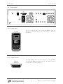
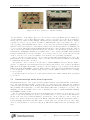
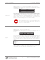
1.5 Serial number and firmware revision
•Serial number
If you need to contact Stanford Research Systems, please have the serial number of your unit
available. The 5-digit serial number is printed on a label affixed to the rear panel. the unit is powered
on. The serial number can also be displayed on the front panel after the unit is powered on by pressing
the [DISPLAY] key.
•Firmware revision
The firmware revision code is shown on the front panel when the unit is powered on.
19 EC301 Potentiostat/Galvanostat/ZRA

2 EC301 basics
2 EC301 basics
2.1 Software
The EC301 is intended to operate with the SRSLab Windows software package. SRSLab can be downloaded
from the SRS web site, www.thinkSRS.com. Complete instructions for SRSLab, in the form of documentation
videos, are also available on the website.
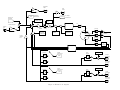
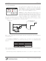
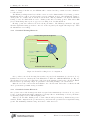
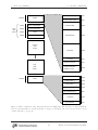
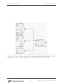
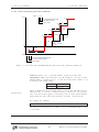
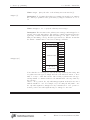
2.2 Functional block diagram
Figure 1 illustrates the major signal paths in the EC301.
20 EC301 Potentiostat/Galvanostat/ZRA
Page is loading ...
Page is loading ...
Page is loading ...
Page is loading ...
Page is loading ...
Page is loading ...
Page is loading ...
Page is loading ...
Page is loading ...
Page is loading ...
Page is loading ...
Page is loading ...
Page is loading ...
Page is loading ...
Page is loading ...
Page is loading ...
Page is loading ...
Page is loading ...
Page is loading ...
Page is loading ...
Page is loading ...
Page is loading ...
Page is loading ...
Page is loading ...
Page is loading ...
Page is loading ...
Page is loading ...
Page is loading ...
Page is loading ...
Page is loading ...
Page is loading ...
Page is loading ...
Page is loading ...
Page is loading ...
Page is loading ...
Page is loading ...
Page is loading ...
Page is loading ...
Page is loading ...
Page is loading ...
Page is loading ...
Page is loading ...
Page is loading ...
Page is loading ...
Page is loading ...
Page is loading ...
Page is loading ...
Page is loading ...
Page is loading ...
Page is loading ...
Page is loading ...
Page is loading ...
Page is loading ...
Page is loading ...
Page is loading ...
Page is loading ...
Page is loading ...
Page is loading ...
Page is loading ...
Page is loading ...
Page is loading ...
Page is loading ...
Page is loading ...
Page is loading ...
Page is loading ...
Page is loading ...
Page is loading ...
Page is loading ...
Page is loading ...
Page is loading ...
Page is loading ...
Page is loading ...
Page is loading ...
Page is loading ...
Page is loading ...
Page is loading ...
Page is loading ...
Page is loading ...
Page is loading ...
Page is loading ...
Page is loading ...
Page is loading ...
Page is loading ...
Page is loading ...
Page is loading ...
Page is loading ...
Page is loading ...
Page is loading ...
Page is loading ...
Page is loading ...
Page is loading ...
Page is loading ...
Page is loading ...
Page is loading ...
Page is loading ...
Page is loading ...
Page is loading ...
Page is loading ...
Page is loading ...
Page is loading ...
Page is loading ...
Page is loading ...
Page is loading ...
Page is loading ...
Page is loading ...
Page is loading ...
Page is loading ...
Page is loading ...
Page is loading ...
Page is loading ...
Page is loading ...
Page is loading ...
Page is loading ...
Page is loading ...
Page is loading ...
Page is loading ...
Page is loading ...
Page is loading ...
Page is loading ...
-
 1
1
-
 2
2
-
 3
3
-
 4
4
-
 5
5
-
 6
6
-
 7
7
-
 8
8
-
 9
9
-
 10
10
-
 11
11
-
 12
12
-
 13
13
-
 14
14
-
 15
15
-
 16
16
-
 17
17
-
 18
18
-
 19
19
-
 20
20
-
 21
21
-
 22
22
-
 23
23
-
 24
24
-
 25
25
-
 26
26
-
 27
27
-
 28
28
-
 29
29
-
 30
30
-
 31
31
-
 32
32
-
 33
33
-
 34
34
-
 35
35
-
 36
36
-
 37
37
-
 38
38
-
 39
39
-
 40
40
-
 41
41
-
 42
42
-
 43
43
-
 44
44
-
 45
45
-
 46
46
-
 47
47
-
 48
48
-
 49
49
-
 50
50
-
 51
51
-
 52
52
-
 53
53
-
 54
54
-
 55
55
-
 56
56
-
 57
57
-
 58
58
-
 59
59
-
 60
60
-
 61
61
-
 62
62
-
 63
63
-
 64
64
-
 65
65
-
 66
66
-
 67
67
-
 68
68
-
 69
69
-
 70
70
-
 71
71
-
 72
72
-
 73
73
-
 74
74
-
 75
75
-
 76
76
-
 77
77
-
 78
78
-
 79
79
-
 80
80
-
 81
81
-
 82
82
-
 83
83
-
 84
84
-
 85
85
-
 86
86
-
 87
87
-
 88
88
-
 89
89
-
 90
90
-
 91
91
-
 92
92
-
 93
93
-
 94
94
-
 95
95
-
 96
96
-
 97
97
-
 98
98
-
 99
99
-
 100
100
-
 101
101
-
 102
102
-
 103
103
-
 104
104
-
 105
105
-
 106
106
-
 107
107
-
 108
108
-
 109
109
-
 110
110
-
 111
111
-
 112
112
-
 113
113
-
 114
114
-
 115
115
-
 116
116
-
 117
117
-
 118
118
-
 119
119
-
 120
120
-
 121
121
-
 122
122
-
 123
123
-
 124
124
-
 125
125
-
 126
126
-
 127
127
-
 128
128
-
 129
129
-
 130
130
-
 131
131
-
 132
132
-
 133
133
-
 134
134
-
 135
135
-
 136
136
-
 137
137
-
 138
138
-
 139
139


Ask a question and I''ll find the answer in the document
Finding information in a document is now easier with AI
Related papers

Other documents
-
 INSE 15 Carded Stick Vacuum Cleaner User manual
-
 Kett PM-410 Operating instructions
-
KEPCO BOP-1KW (MG, ME) Operating instructions
-
-
 Gamry Instruments Reference 600 User guide
-
 INSE V70 User manual
-
MTT MS3700MS3727 User manual
-
 HOZAN F-109 Owner's manual
-
Ludlum Measurements 9-4 Owner's manual
-
 Newtons4th PSM3750 NumetriQ Communications Manual


