Page is loading ...

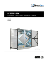
HE07IN
HE10IN
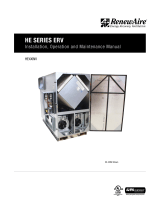
HE SERIES ERV
Installation, Operation and Maintenance Manual
Model: HE10INV shown

1.800.627.44992
HE-Series Indoor
ERV
EC motors (ECM) are NOT suitable for use with solid state
speed control. They already have speed control built into the
motor electronics.
WARNING
Les moteurs EC (ECM) ne conviennent PAS pour une
utilisation avec un contrôle de vitesse à semi-conducteurs.
Ils ont déjà un contrôle de vitesse intégré à l'électronique
du moteur.
AVERTISSEMENT
ARC FLASH AND ELECTRIC SHOCK HAZARD
Arc flash and electric shock hazard. Disconnect all electric
power supplies, verify with a voltmeter that electric power
is off and wear protective equipment per NFPA 70E before
working within electric control enclosure. Failure to comply can
cause serious injury or death.
Customer must provide earth ground to unit, per NEC, CEC and
local codes, as applicable.
Before proceeding with installation, read all instructions, veri-
fying that all the parts are included and check the nameplate to
be sure the voltage matches available utility power.
The line side of the disconnect switch contains live
high-voltage.
The only way to ensure that there is NO voltage inside the unit
is to install and open a remote disconnect switch and verify
that power is off with a volt meter. Refer to unit electrical
schematic. Follow all local codes.
WARNING
RISK OF ELECTRIC SHOCK OR EQUIPMENT DAMAGE
Whenever electrical wiring is connected, disconnected or
changed, the power supply to the ERV and its controls must
be disconnected. Lock and tag the disconnect switch or circuit
breaker to prevent accidental reconnection of electric power.
CAUTION
RISK OF CONTACT WITH HIGH SPEED MOVING PARTS
Disconnect all local and remote power supplies, verify with
a voltmeter that electric power is off and all fan blades have
stopped rotating before working on the unit.
Do not operate this unit with any cabinet panels removed.
CAUTION
This equipment is to be installed by following Industry Best
Practices and all applicable codes. Any damage to compo-
nents, assemblies, subassemblies or the cabinet which is
caused by improper installation practices will void
the warranty.
IMPORTANT
This unit is for ventilating finished structures only. It is not to
be used until after all construction has been completed and
construction debris and dust are cleaned from the
Occupied Space.
IMPORTANT
This unit is intended for general ventilating and heating only.
Do not use to exhaust hazardous or explosive materials and
vapors. Do not connect this equipment to range hoods, fume
hoods or collection systems for toxics.
IMPORTANT

31.800.627.4499
HE-Series Indoor ERV
OWNER INFORMATION
READ AND SAVE THIS MANUAL/LIRE ET CONSERVER CE MANUEL
UNIT INFORMATION
Record information as shown below.
In the unlikely event that factory assistance is ever required, information located on the unit
label will be needed.
Locate the RenewAire unit label found on the outside of the unit.
NOTE: This information is for purposes of identifying the unit-specific option data from the
Option Code.
H-
- IE -
J N -
Option Code:
Serial Number:
SO #:
NOTE: This page
is to be completed
by the installing
contractor. The completed
document is to be turned
over to the owner after
start up.
UNIT INFORMATION
UNIT LABEL (TYPICAL)
This manual contains space for maintaining written records of unit maintenance and/
or repairs. See Section 7.7 Maintenance Records. At the time the ERV is commissioned, a
maintenance schedule should be developed by the user to incorporate monthly and seasonal
maintenance and include start up maintenance tasks as described in this manual.
NOTICE NOTE: This unit is
an Energy Recovery
Ventilator, or ERV.
It is commonly referred to
throughout this manual as
an ERV.

1.800.627.44994
HE-Series Indoor
ERV
TABLE OF CONTENTS
1.0 OVERVIEW 7
1.1 DESCRIPTION .........................................................7
1.2 AIRFLOW ................................................................8
2.0 COMPONENT DESCRIPTIONS 8
2.1 CABINET ................................................................8
2.2 ENTHALPIC CORES .................................................8
2.3 IMPELLER/MOTOR ASSEMBLIES .............................8
2.4 E-BOX ....................................................................9
2.5 FILTERS .................................................................9
2.6 FACTORY INSTALLED OPTIONS ................................9
3.0 SHIPPING/RECEIVING/HANDLING 10
3.1 UNIT WEIGHTS AND DIMENSIONS .........................10
3.1.1 HE07IN Unit Dimensions and Weight: ................................. 10
3.1.2 HE07IN Maximum Shipping Dimensions and Weight ........... 10
3.1.3 HE10IN Unit Dimensions and Weight: ................................. 10
3.1.4 HE10IN Maximum Shipping Dimensions and Weight ...........10
3.2 RIGGING AND CENTER OF GRAVITY .......................11
3.2.1 HE07IN/HE10IN Hoisting Weights and COG ........................ 11
3.3 RECEIVING ...........................................................12
3.4 STORAGE .............................................................12
4.0 UNIT PLACEMENT 13
4.1 BEFORE YOU BEGIN ..............................................13
4.2 SERVICE CLEARANCES .........................................13
4.3 SOUND ATTENUATION ........................................... 15
4.3.1 Ducts ............................................................................... 15
4.3.2 Radiated Noise ................................................................. 15
4.3.3 Connecting Ducts to Unit .................................................. 15
5.0 INSTALLATION 16
5.1 DUCTWORK ..........................................................16
5.1.1 Ducts to the Outside .......................................................... 16
5.1.2 Inside Ductwork System .................................................... 16
5.1.3 Duct Insulation ..................................................................16
5.1.4 Adjust Fan Speed to Set and Balance Airflow Rates ........... 16
5.2 FLOOR INSTALLATION ........................................... 16
5.3 SUSPENDED MOUNT ............................................16
5.3.1 Hanging Unit From Structure ............................................ 16
5.3.2 Hanging Vibration Isolators ...............................................16
5.3.3 Hanging Bracket Kit .......................................................... 17
5.4 ELECTRICAL REQUIREMENTS ................................ 18
5.4.1 Factory-Recommended Electric Service Entry .................... 18
5.4.2 Low Voltage Control System ............................................. 19
5.4.3 How to Reset the 24VAC Circuit Breaker ............................ 19
5.4.4 Limits of Power Output .................................................... 19
5.5 WIRING SCHEMATICS............................................20
5.6 EXTERNAL CONTROL CONNECTIONS .....................22
5.6.1 Fan Enable Field Circuit .....................................................22
5.6.2 Fan Speed Selection Field Circuit ......................................22
5.6.3 Fan Speed Adjustment ...................................................... 22
5.6.4 Analog Signal for Controlling SPEED 2 ............................... 22
5.7 QUICK-START FOR TESTING CORRECT
PH WIRING ...........................................................22
6.0 OPERATION 23
6.1 PRINCIPLE OF OPERATION ....................................23
6.2 PRE-START UP .....................................................23
6.2.1 Verify Voltages ..................................................................23
6.2.2 Verify Transformer Wiring .................................................23
6.2.3 Inspect Filters ..................................................................23
6.2.4 Inspect Foam Gasketing ....................................................23
6.2.5 Inspect Fans .....................................................................23
6.2.6 Inspect and Clean the Cabinet Interior ............................... 23
6.2.7 Inspect Ductwork Connections .......................................... 23
6.3 UNIT START UP .....................................................23
6.3.1 Starting Up ECM Units.......................................................23
6.4 BALANCING AIRFLOW ...........................................24
6.4.1 Filter Pressure Drop ..........................................................25
6.5 NORMAL OPERATION ............................................26
6.6 OPERATION IN EXTREME COLD WEATHER .............27
7.0 MAINTENANCE 27
7.1 MAINTENANCE 24 HRS. AFTER START UP .............27
7.2 MAINTENANCE 30 DAYS AFTER START UP ............. 27
7.3 MAINTENANCE SCHEDULE .................................... 27
7.4 FILTERS ...............................................................27
7.5 IMPELLER MOTOR ................................................27
7.6 ENTHALPIC CORE .................................................28
7.6.1 Enthalpic Core Maintenance ..............................................28
7.6.2 Enthalpic Core Removal ....................................................28
7.6.3 Enthalpic Core Replacement ..............................................28
7.7 MAINTENANCE RECORDS .....................................29
7.8 SERVICE PARTS .................................................... 30
8.0 TROUBLESHOOTING 31
9.0 FACTORY ASSISTANCE 31

51.800.627.4499
HE-Series Indoor ERV
TABLE OF CONTENTS
TABLE OF ILLUSTRATIONS
Figure 1.2.0 Airflow Orientations .........................................................................................................8
Figure 2.4.0 E-Box Without Controls ...................................................................................................9
Figure 3.2.0 HE07INH Weights and COG ............................................................................................ 11
Figure 3.2.1 HE07INV Weights and COG ............................................................................................ 11
Figure 3.2.2 HE10INH Weights and COG ............................................................................................ 12
Figure 3.2.3 HE10INV Weights and COG ............................................................................................ 12
Figure 4.2.0 HE07INH Service Clearances, Top View ......................................................................... 13
Figure 4.2.1 HE07INV Service Clearances, Top View .......................................................................... 13
Figure 4.2.2 HE10INH Service Clearances, Top View .......................................................................... 14
Figure 4.2.3 HE10INV Service Clearances, Top View .......................................................................... 14
Figure 5.3.0 Ceiling Hung with Optional Vibration Isolators ................................................................ 17
Figure 5.3.1 Hanging Bracket Kit ....................................................................................................... 17
Figure 5.4.0 E-Box Wiring Entry Points .............................................................................................. 18
Figure 5.5.0 Single Phase Unit, Standard ..........................................................................................20
Figure 5.5.1 Three Phase Unit, Standard (HE10IN Only) .....................................................................21
Figure 5.6.0 Field Circuit Detail .........................................................................................................22
Figure 6.4.0 Pressure Port Locations ................................................................................................ 24
Figure 6.4.1 Initial Pressure Drop of MERV 8 Filters, Supplied with HE07 ........................................... 25
Figure 6.4.2 Initial Pressure Drop of MERV 13 Filters, Available as an HE07 Accessory ....................... 25
Figure 6.4.3 Initial Pressure Drop of MERV 8 Filters, Supplied with HE10 ........................................... 26
Figure 6.4.4 Initial Pressure Drop of MERV 13 Filters, Available as an HE10 Accessory ....................... 26
Figure 7.8.0 HE07IN Service Parts ....................................................................................................30
Figure 7.8.1 HE10IN Service Parts ..................................................................................................... 31

1.800.627.44996
HE-Series Indoor
ERV
CONFIGURATION CODE
HE MODELS
CONFIGURATION GUIDE
Note: Not all options are available on every model.
For Technical Support E-mail: [email protected]
To Place an Order E-mail: [email protected]
MODEL NUMBER H E J - - - -
DIGIT NUMBER 1 2 3 4 5 6 7 8 9 10 11 12 13 14 15 16 17 18 19 20 21 22 23 24 25
Digits 1–5: Model Digit 18: Flow Control* (see Restrictions 12, 13, & 14)
"HE07-", "HE10-", "HE1.5", "HE-2X", "-" = No Isolation Dampers (with no Bypass)
"HE-3X", "HE-4X", "HE-6X", "HE-8X" "D" = Motorized Damper both Airstreams (with no Bypass)
"E" = Motorized Damper EA or RA Airstream (with no Bypass)
Digits 7–8: Location "F" = Motorized Damper FA or OA Airstream (with no Bypass)
"IN" = Indoor "S" = Backdraft Damper OA Airstream (with no Bypass)
"RT" = Rooftop "R" = Backdraft Damper EA Airstream (with no Bypass)
"B" = Backdraft Damper both Airstreams (with no Bypass)
Digit 9: Orientation (see Restriction 1) "T" = Motorized Damper OA, Backdraft Damper EA (with no Bypass)
"V", "H" (Indoor Units) "0" = Dry Bulb Face and Bypass Dampers only
"V", "H", "R", "F", "C" (Rooftop Units) "1" = Dry Bulb Bypass with Motorized Dampers all Airstreams
"4" = Dry Bulb Bypass with Backdraft Damper OA Airstream
Digit 11: Wall Type "5" = Enthalpy Face and Bypass Dampers only
"S" = Single "6" = Enthalpy Bypass with Motorized Dampers all Airstreams
"D" = Double "9" = Enthalpy Bypass with Backdraft Damper OA Airstream
Digit 12: Phase (See Restriction 2, 8, 11, & 20) Digit 19: Unit Control (see Restrictions 15, 16, 17, 18, 19, 20, & 21)
"1" = Single Phase "A" = Standard Unit Control Wiring
"3" = Three Phase "D" = Independent Blower Control (HE1.5 only)
"V" = Onboard VFD Both Airstreams
Digit 13: Voltage (see Restrictions 3, 4, 5, 6, 7, 11, & 19) "G" = Terminal Strip for EC Motors or Impellers
"1" = 120V
"4" = 460V Digit 20: Disconnect
"5" = 208-230V "N" = Non-Fused (Standard)
"8" = 575V "F" = Fused
"9" = 277V
Digit 21: Unit Control Enhancements (see Restrictions 16 & 22)
Digit 14: FA Horsepower (see Restrictions 7, 8, 9, 10, & 21) "T" = Transformer with Isolation Relay (Standard)
"E" = EC Direct Drive Motors (HE07-, HE-10-, and HE1.5 only) "1" = Enhanced Controls
"A" = Advanced EC Direct Drive Motorized Impellers (HE07- and HE10- only) "2" = Premium Controls
"B" = Intermediate EC Direct Drive Motorized Impellers (HE07- only) "3" = Enhanced Controls with BACnet License
"S" = Standard Impellers (HE1.5 only) "4" = Premium Controls with BACnet License
"U" = 1.5HP (HE-2X only)
"V" = 2HP (HE-2X, HE-3X, HE-4X only) Digit 22: Filter Options (see Restriction 22)
"W" = 3HP (HE-3X, HE-4X only) "-" = None (Standard)
"X" = 5HP (HE-3X, HE-4X, HE-6X, HE-8X only) "F" = Filter Monitor Both Airstreams
"Y" = 7.5HP (HE-6X, HE-8X only)
"Z" = 10HP (HE-8X only) Digit 23: Other Options
"-" = None (Reserved)
Digit 15: EA Horsepower (see Restrictions 7, 8, 9, 10, & 21)
"E" = EC Direct Drive Motors (HE07-, HE-10-, and HE1.5 only) Digit 24: Paint and Customization
"A" = Advanced EC Direct Drive Motorized Impellers (HE07- and HE10- only) "-" = None
"B" = Intermediate EC Direct Drive Motorized Impellers (HE07- only) "W" = White Paint
"S" = Standard Impellers (HE1.5 only) "C" = Custom Paint
"U" = 1.5HP (HE-2X only) "X" = Custom Unit
"V" = 2HP (HE-2X, HE-3X, HE-4X only)
"W" = 3HP (HE-3X, HE-4X only) Digit 25: Safety Listing (see Restriction 23)
"X" = 5HP (HE-3X, HE-4X, HE-6X, HE-8X only) "L" = Listed
"Y" = 7.5HP (HE-6X, HE-8X only) "N" = Non-Listed
"Z" = 10HP (HE-8X only)
*NOTES:
Digit 6 "J" = G5 Core Type. Digits 10, 16, and 17 are not used in these models.
*Digit 18: For units with the Bypass Option, the face damper also acts as an isolation damper in the EA or RA airstream.
Restrictions:
1: Orientation Code "C" not available with models HE07-, HE10-, HE-6X, HE-8X, HE1.5
2: Phase Code “3” not available with model HE07-.
3: Voltage Codes "1" & "9" only available with Phase Code "1" (Single-Phase).
4: Voltage Codes "4" & "8" only available with Phase Code "3" (Three-Phase).
5: Voltage Code "8" (575V) not available with models HE07-, HE10-, & HE1.5.
CONFIGURATION CODE
NOTE: Not all options are available on every model.
MODEL NUMBER H E - J I N - - -
DIGIT NUMBER 1 2 3 4 5 6 7 8 9 10 11 12 13 14 15 16 17 18 19 20 21 22 23 24 25

71.800.627.4499
HE-Series Indoor ERV
1.0 OVERVIEW
1.1 DESCRIPTION
OVERVIEW
The HE07IN/HE10IN Energy Recovery Ventilator (ERV) is a device for recovering both sensible energy
(heat) and latent energy (moisture) from the Exhaust Air from an Occupied Space and injecting those
energies into an incoming Outside Air stream. It accomplishes this task by forcing the two airstreams
through enthalpic cores, where the energy exchange takes place. The two airstreams pass through
the enthalpic cores at right angles and the airstreams never mix together. See Section 2.2 Enthalpic
Cores in this manual.
Each ERV has two electric impellers, one for each airstream. Impellers have electronically
commutated motors controlled by a printed circuit board, a RenewAire Commercial Controller, or by
a BMS. There are a number of different control devices available to control the operation or speed of
the unit fans. For further information on available control accessories, see the HE RenewAire catalog.
There are two types of HE07/HE10 units, one for indoor installations and one for rooftop, or outdoor,
installation. This manual is for the HE07IN/HE10IN, which is the indoor unit. For information on the
outdoor version of this product, see the HE07RT/HE10RT Installation and Operation Manual.
These ERVs are commonly installed as part of an air-handling system that provides heating and
cooling of Supply Air. They can also be installed to operate as stand-alone devices when ducted
directly to and from the Occupied Space.
Each unit has an integral 24VAC power supply that is used internally and can also be used as a
power source for other optional control devices.
The HE07IN/HE10IN units are low-maintenance, requiring periodic replacement of the air filters
and annual vacuuming of the enthalpic cores. See Section 7.0 Unit Maintenance in this manual.
IMPORTANT
It is important to understand and use the equipment airstream terminology as it is used in
this manual. The airstreams are defined as:
u OUTSIDE AIR (OA): Air taken from the external atmosphere and, therefore, not previously
circulated through the system.
u SUPPLY AIR (SA): Air that is downstream of the enthalpic cores and is ready for condition-
ing or for return to the Occupied Space.
u RETURN AIR (RA): Air that is returned to the ERV from a conditioned space.
u EXHAUST AIR (EA): Air that is removed from a heating or cooling appliance or from the
Occupied Space and discharged.

1.800.627.44998
HE-Series Indoor
ERV
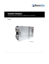
1.2 AIRFLOW
FIGURE 1.2.0 AIRFLOW ORIENTATIONS
MODEL DESCRIPTION OF DUCT
CONNECTION CONFIGURATION
HE07INV
HE10INV
Return Air [RA] and Outside Air [OA] enter on the opposite sides
of unit.
HE07INH
HE10INH Return Air [RA] and Outside Air [OA] enter on the same side of unit.
SA
EA
RA OA
HEIN except 6x 8x, LEIN
INV
SA
OA
EA
RA
HEIN except 6x 8x, LEIN
INH
There are two different airflow options for the HE07IN/HE10IN. They are:
u HE07INV/HE10INV
u HE07INH/HE10INH
The airflow configuration is indicated by digit 9 of the Configuration Code.
2.0 COMPONENT DESCRIPTIONS
2.1 CABINET
The cabinet for the HE07IN/HE10IN is made of 20 gauge galvanized steel and has 1" thick high-
density, foil-backed insulation on the inside. Units are available in either single-wall or double-
wall construction. Doors are hinged and are fitted with stainless steel machine screws through
the faces to prevent accidental opening of the doors when the unit is in operation. Doors may be
completely removed by removing the hinge pins. Duct flanges are available as an accessory for
all airstream openings for connection of field-supplied ductwork.
2.2 ENTHALPIC CORES
All HE07IN/HE10IN ERVs use a static-plate enthalpic core. The enthalpic cores transfer both
latent and sensible energies between the airstreams. Gasketing is pre-installed on the cores
and must be positioned to provide a proper air seal. For information on annual maintenance of
the cores, see Section 7.0 Maintenance in this manual.
2.3 IMPELLER/MOTOR ASSEMBLIES
Low airflow can cause
fouling of the enthalpic
cores. The ERV must
never be operated without
clean filters in place and
minimum airflow must be
greater than 250 CFM per
full-sized core.
CAUTION
There are two impeller and motor assemblies in each ERV.
COMPONENT DESCRIPTIONS

91.800.627.4499
HE-Series Indoor ERV
2.4 E-BOX
Every HE07IN/HE10IN is equipped with what is known as an “E-Box.” High-voltage supply
wiring and low-voltage control wiring is all terminated here. If optional integrated programmable
controls are installed, an additional 24VAC transformer is installed here to power both the
controller and its dedicated sensors.
COMPONENT DESCRIPTIONS
FIGURE 2.4.0 E-BOX WITHOUT CONTROLS
GROUND BUS
POWER SUPPLY WIRING
CONNECTED HERE ON TOP
OF DISCONNECT SWITCH
OPTIONAL UNIT FUSING
24VAC STEP-DOWN TRANSFORMER
(WITH BUILT-IN CIRCUIT BREAKER)
EC CONTROL BOARD DISCONNECT SWITCH
POTENTIOMETER FOR SPEED 2 ADJUSTMENT
BOARD-MOUNTED
POTENTIOMETERS FOR
SPEED 1 ADJUSTMENT
(USE 5/64" SLOTTED
SCREWDRIVER)
2.5 FILTERS
All HE07IN units come equipped with two MERV 8 14" x 20" x 2" (nominal) pleated filters. All
HE10IN units come equipped with two MERV 8 20" x 20" x 2" (nominal) pleated filters. MERV
13 filters can be ordered as an accessory and are shipped loose.
u HE07IN: (2) 14" x 20" x 2" (nominal) pleated filters. Actual size: 13.5" x 19.5" x 1.75"
u HE10IN: (2) 20" x 20" x 2" (nominal) pleated filters. Actual size: 19.5" x 19.5" x 1.75"
u Minimum recommended effectiveness: MERV 6.
2.6 FACTORY INSTALLED OPTIONS
All HE07IN/HE10IN units can be ordered with factory installed options. See Unit Configuration
Code on page 6.
Options will have supplemental manuals shipped with the unit.
For Commercial Controls, see Enhanced Controls Supplemental Manual or Premium Controls
Supplemental Manual.
For Filter Alarm, see Filter Alarm Supplemental Manual.
For Isolation Dampers, see Isolation Dampers Supplemental Manual.
For Economizer/Bypass, see Bypass Economizer Supplemental Manual.

1.800.627.449910
HE-Series Indoor
ERV
SHIPPING/RECEIVING
3.1 UNIT WEIGHTS AND DIMENSIONS
3.1.1 HE07IN Unit Dimensions and Weight:
49 1/2" L x 17 1/2" W x 50 1/4" H
148-278 lbs., varies by option(s)
3.0 SHIPPING/RECEIVING/HANDLING
HE07IN/HE10IN units are palletized at the factory and then shipped by common carrier.
Upon receipt by the installer, the shipment should be inspected for shipping damage, prior to
unloading. Any discovered shipping damage should be immediately reported to the RenewAire
sales rep and the damage must be recorded on the Bill Of Lading, prior to signing for
acceptance of the shipment. The unit can be handled with a fork lift or equipment hoist.
Prior to moving the unit, verify that all latches and securing bolts on the cabinet doors are
tightly fastened.
If an equipment hoist is used for moving the HE07IN/HE10IN unit, unscrew the sheet metal
plates that hold the unit to the pallet. Use straps and a spreader bar to hoist the unit. The
straps must be spaced to ensure the unit is level and the center of gravity is positioned properly
between them. Unit hoisting weights and Center of Gravity are detailed in Sections 3.1 and 3.2
in this manual.
Perform a test lift to make sure the unit is being hoisted level and is secure.
Place the HE07IN/HE10IN unit on a flat surface where it will be protected from the weather and
incidental damage. Do not remove protective coverings from any duct openings and keep the
doors secured and tightly closed.
3.1.2 HE07IN Maximum Shipping Dimensions and Weight
60" L x 30" W x 55 1/4" H
310 lbs.
3.1.3 HE10IN Unit Dimensions and Weight:
49 1/2" L x 23 3/4" W x 50 1/4"
194-350 lbs., varies by option(s)
3.1.4 HE10IN Maximum Shipping Dimensions and Weight
60" L x 30" W x 55 1/4" H
385 lbs.

111.800.627.4499
HE-Series Indoor ERV
SHIPPING/RECEIVING
36.45 (W)
10.38 (L)
19.82 (A)
4.19 (B)
LR
RR
RF
LF
000
REVISION
DESCRIPTION
DATE
BY
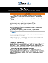
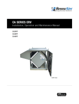
BASIC UNIT WEIGHTS (lbs.)
Motors
UNIT
LF
LR
RR
RF
Standard (1P/208-230V)
148 40 27 32 48
Intermediate (1P/208-230V)
158 43 29 35 51
Advanced (1P/115V)
158 43 29 35 51
Advanced (1P/208-230V)
170 46 31 37 55
ADDITIONAL WEIGHTS FOR OPTIONS (lbs.)
Options
UNIT
LF
LR
RR
RF
Double Wall
53 13.25 13.25 13.25 13.25
Bypass
10010
RA or EA Damper
12.5 6.25 6.25 0 0
OA or FA Damper
12.5 6.25 6.25 0 0
Total Selected Weights
INDICATES LOCATIONS AT WHICH CORNER WEIGHTS ARE
CALCULATED: LEGS.
Center of gravity: From Left A = 19.82", From Front B = 4.19" (+/- 2")
SEE BILL OF MATERIALS
SEE BILL OF MATERIALS
ASSEMBLY
CORNER WEIGHTS HE07INH
147623
FINISH:
MATERIAL:
UNLESS OTHERWISE SPECIFIED
DIMENSIONS ARE IN INCHES
TOLERANCES:
LINEAR
0.015
HOLE SIZE
0.005
ANGULARITY
3
SURFACE FINISH =
63 MICRONINCH MINIMUM
X.X
INSPECTION
REMOVE ALL BURRS, BREAK SHARP EDGES,
APPLICABLE STANDARDS: DIM.
AND TOL. ANSI Y14.5
10/2/2023
CRF
THIS DOCUMENT CONTAINS INFORMATION
WHICH IS PROPRIETARY TO RENEWAIRE LLC.
THE INFORMATION CONTAINED HEREON
SHALL NOT BE DISCLOSED, DUPLICATED, USED
IN WHOLE OR IN PART FOR ANY PURPOSE
OTHER THAN TO EVALUATE THIS DOCUMENT
WITHOUT WRITTEN CONSENT OF RENEWAIRE
LLC.
DWG NO.
RENEWAIRE LLC.
201 RAEMISCH RD. WAUNAKEE, WI. 53597 USA
TEL: (608) 221-4499 FAX: (608) 221-2824 TOLL FREE: (800) 627-4499
LBS
180.48
WEIGHT:
1
OF
1
SHEET
TITLE:
DO NOT SCALE THIRD ANGLE PROJECTION
1:12
SCALE:
000
REV
A
SIZE
CHECKED:
DRAWN:
eSIGNATURES
DATE
A A
B B
2
2
1
1
FIGURE 3.2.0 HE07INH WEIGHTS AND COG
36.45 (W)
10.38 (L)
17.92 (A)
4.20 (B)
LR
RR
RF
LF
000
REVISION
DESCRIPTION
DATE
BY
BASIC UNIT WEIGHTS (lbs.)
Motors
UNIT
LF
LR
RR
RF
Standard (1P/208-230V)
148 45 30 29 43
Intermediate (1P/208-230V)
158 48 33 31 46
Advanced (1P/115V)
158 48 33 31 46
Advanced (1P/208-230V)
170 51 35 34 50
ADDITIONAL WEIGHTS FOR OPTIONS (lbs.)
Options
UNIT
LF
LR
RR
RF
Double Wall
53 13.25 13.25 13.25 13.25
Bypass
10100
RA or EA Damper
12.5 0 0 6.25 6.25
OA or FA Damper
12.5 6.25 6.25 0 0
Total Selected Weights
INDICATES LOCATIONS AT WHICH CORNER WEIGHTS ARE
CALCULATED: LEGS.
Center of gravity: From Left A = 17.92", From Front B = 4.20" (+/- 2")
SEE BILL OF MATERIALS
SEE BILL OF MATERIALS
ASSEMBLY
BEDROCK 450 V4
FINISH:
MATERIAL:
UNLESS OTHERWISE SPECIFIED
DIMENSIONS ARE IN INCHES
TOLERANCES:
LINEAR
0.015
HOLE SIZE
0.005
ANGULARITY
3
SURFACE FINISH =
63 MICRONINCH MINIMUM
X.X
INSPECTION
REMOVE ALL BURRS, BREAK SHARP EDGES,
APPLICABLE STANDARDS: DIM.
AND TOL. ANSI Y14.5
10/2/2023
CRF
THIS DOCUMENT CONTAINS INFORMATION
WHICH IS PROPRIETARY TO RENEWAIRE LLC.
THE INFORMATION CONTAINED HEREON
SHALL NOT BE DISCLOSED, DUPLICATED, USED
IN WHOLE OR IN PART FOR ANY PURPOSE
OTHER THAN TO EVALUATE THIS DOCUMENT
WITHOUT WRITTEN CONSENT OF RENEWAIRE
LLC.
DWG NO.
RENEWAIRE LLC.
201 RAEMISCH RD. WAUNAKEE, WI. 53597 USA
TEL: (608) 221-4499 FAX: (608) 221-2824 TOLL FREE: (800) 627-4499
LBS
182.30
WEIGHT:
1
OF
1
SHEET
TITLE:
DO NOT SCALE THIRD ANGLE PROJECTION
1:12
SCALE:
000
REV
A
SIZE
CHECKED:
DRAWN:
eSIGNATURES
DATE
A A
B B
2
2
1
1
FIGURE 3.2.1 HE07INV WEIGHTS AND COG
3.2 RIGGING AND CENTER OF GRAVITY
3.2.1 HE07IN/HE10IN Hoisting Weights and COG
Spreader bars and straps are recommended in order to avoid damage to the unit.

1.800.627.449912
HE-Series Indoor
ERV
SHIPPING/RECEIVING
36.46 (W)
16.57 (L)
20.49 (A)
7.31 (B)
LR
RR
RF
LF
000
REVISION
DESCRIPTION
DATE
BY
BASIC UNIT WEIGHTS (lbs.)
Motors
UNIT
LF
LR
RR
RF
Standard (1P/208-230V)
204 50 39 51 64
Advanced (1P/115V)
194 47 37 48 61
Advanced (1P/208-230V)
194 47 37 48 61
Advanced (3P/460V)
226 55 44 56 71
ADDITIONAL WEIGHTS FOR OPTIONS (lbs.)
Options
UNIT
LF
LR
RR
RF
Double Wall
86 21.5 21.5 21.5 21.5
Bypass
10010
RA or EA Damper
16 8 8 0 0
OA or FA Damper
16 8 8 0 0
Total Selected Weights
INDICATES LOCATIONS AT WHICH CORNER WEIGHTS ARE
CALCULATED: LEGS.
Center of gravity: From Left A = 20.49", From Front B = 7.31" (+/- 2")
SEE BILL OF MATERIALS
SEE BILL OF MATERIALS
ASSEMBLY
CORNER WEIGHTS HE10INH
147625
FINISH:
MATERIAL:
UNLESS OTHERWISE SPECIFIED
DIMENSIONS ARE IN INCHES
TOLERANCES:
LINEAR
0.015
HOLE SIZE
0.005
ANGULARITY
3
SURFACE FINISH =
63 MICRONINCH MINIMUM
X.X
INSPECTION
REMOVE ALL BURRS, BREAK SHARP EDGES,
APPLICABLE STANDARDS: DIM.
AND TOL. ANSI Y14.5
10/3/2023
CRF
THIS DOCUMENT CONTAINS INFORMATION
WHICH IS PROPRIETARY TO RENEWAIRE LLC.
THE INFORMATION CONTAINED HEREON
SHALL NOT BE DISCLOSED, DUPLICATED, USED
IN WHOLE OR IN PART FOR ANY PURPOSE
OTHER THAN TO EVALUATE THIS DOCUMENT
WITHOUT WRITTEN CONSENT OF RENEWAIRE
LLC.
DWG NO.
RENEWAIRE LLC.
201 RAEMISCH RD. WAUNAKEE, WI. 53597 USA
TEL: (608) 221-4499 FAX: (608) 221-2824 TOLL FREE: (800) 627-4499
LBS
254.12
WEIGHT:
1
OF
1
SHEET
TITLE:
DO NOT SCALE THIRD ANGLE PROJECTION
1:12
SCALE:
000
REV
A
SIZE
CHECKED:
DRAWN:
eSIGNATURES
DATE
A A
B B
2
2
1
1
FIGURE 3.2.2 HE10INH WEIGHTS AND COG
3.3 RECEIVING
Upon receipt of the HE07IN/HE10IN, inspect the unit for obvious external damage. If damage
is observed, take digital pictures and report the damage to your RenewAire representative.
Note the damage on the carrier’s Bill of Lading. Depending on expected transport and storage
conditions, the unit may have only the duct openings covered, it may be stretch-wrapped or it
may be crated. Do not unwrap the unit at this time. The unit will normally be moved to its final
location while still wrapped and attached to its pallet.
The preferred method of hoisting the HE07IN/HE10IN from the carrier truck is by using a
construction forklift or a crane.
Once the unit is unwrapped, prevent dirt and debris from entering the cabinet by covering any
duct openings that do not have attached dampers. Keep the duct openings covered until it’s
time to connect ductwork.
36.46 (W)
16.57 (L)
18.22 (A)
7.31 (B)
LR
RR
RF
LF
000
REVISION
DESCRIPTION
DATE
BY
BASIC UNIT WEIGHTS (lbs.)
Motors
UNIT
LF
LR
RR
RF
Standard (1P/208-230V)
204 57 45 45 57
Advanced (1P/115V)
194 54 43 43 54
Advanced (1P/208-230V)
194 54 43 43 54
Advanced (3P/460V)
226 63 50 50 63
ADDITIONAL WEIGHTS FOR OPTIONS (lbs.)
Options
UNIT
LF
LR
RR
RF
Double Wall
86 21.5 21.5 21.5 21.5
Bypass
10100
RA or EA Damper
16 0 0 6.25 6.25
OA or FA Damper
16 8 8 0 0
Total Selected Weights
INDICATES LOCATIONS AT WHICH CORNER WEIGHTS ARE
CALCULATED: LEGS.
Center of gravity: From Left A = 18.22", From Front B = 7.31" (+/- 2")
SEE BILL OF MATERIALS
SEE BILL OF MATERIALS
ASSEMBLY
CORNER WEIGHTS HE10INV
147626
FINISH:
MATERIAL:
UNLESS OTHERWISE SPECIFIED
DIMENSIONS ARE IN INCHES
TOLERANCES:
LINEAR
0.015
HOLE SIZE
0.005
ANGULARITY
3
SURFACE FINISH =
63 MICRONINCH MINIMUM
X.X
INSPECTION
REMOVE ALL BURRS, BREAK SHARP EDGES,
APPLICABLE STANDARDS: DIM.
AND TOL. ANSI Y14.5
10/3/2023
CRF
THIS DOCUMENT CONTAINS INFORMATION
WHICH IS PROPRIETARY TO RENEWAIRE LLC.
THE INFORMATION CONTAINED HEREON
SHALL NOT BE DISCLOSED, DUPLICATED, USED
IN WHOLE OR IN PART FOR ANY PURPOSE
OTHER THAN TO EVALUATE THIS DOCUMENT
WITHOUT WRITTEN CONSENT OF RENEWAIRE
LLC.
DWG NO.
RENEWAIRE LLC.
201 RAEMISCH RD. WAUNAKEE, WI. 53597 USA
TEL: (608) 221-4499 FAX: (608) 221-2824 TOLL FREE: (800) 627-4499
LBS
254.12
WEIGHT:
1
OF
1
SHEET
TITLE:
DO NOT SCALE THIRD ANGLE PROJECTION
1:12
SCALE:
000
REV
A
SIZE
CHECKED:
DRAWN:
eSIGNATURES
DATE
A A
B B
2
2
1
1
FIGURE 3.2.3 HE10INV WEIGHTS AND COG
3.4 STORAGE
Units that must be stored prior to installation should be left on their pallets and protected from
weather and physical damage. Units must be placed on a level surface to prevent wracking of
the pallet and the HE07IN/HE10IN. All access doors must be secured with all available hardware
(door latches and securing bolts) and all openings into the cabinet must be sealed to prevent
entry of dust, dirt and debris.

131.800.627.4499
HE-Series Indoor ERV
4.0 UNIT PLACEMENT
4.1 BEFORE YOU BEGIN
The HE07IN/HE10IN is designed for installation in a sheltered location, out of the weather. The
preferred mounting location is to place the unit on a concrete floor, although it can also be
suspended from a ceiling or other structural support. See Section 5.3, Suspended Mount, in
this manual.
For all installations, maintain needed service clearances as shown on the dimensioned
drawings located in Section 4.2 of this manual. In addition, if the optional Bypass Economizer
is ordered, additional clearance will be required for the extra bypass duct. See the RenewAire
Supplemental Manual for Bypass Economizer or further information and clearance details
specific to the HE07IN/HE10IN units.
For all floor-mount installations, the unit should be set on its factory-provided adjustable legs
and leveled. Select a location that is central to the inside duct runs and close to both the
exhaust duct (to the outside) and also to the OA duct (from the outside).
The EA outlet and the OA inlet on the outside of the building should be at least 10' apart to
avoid cross-contamination. Comply with all local building codes in the positioning of the duct
openings. Do not position the EA outlet in a location where it will dump EA into any enclosed or
occupied space. The duct inlets and outlets should be screened against insects and vermin and
should be shielded from the weather to prevent entry of rain or snow.
4.2 SERVICE CLEARANCES
37 5/8" Case
5" Damper
Farme. Typ.
1 3/8" Duct
Flange, Typ.
C
L
15 1/2"
Alternate
7/8" Knockout
Power In
Bottom of Unit
RA
OA
EA
SA
Pressure
Ports (4) Typ.
Leveling
Feet (4)
Door-interlocked
Disconnect Switch
1 7/8"
5 1/8"
34 1/4"
2 3/4"
50 1/4" Overall
12"x12" Duct Flanges,
Accessory
10"x10" Airflow
Opening
Alternate
7/8" Knockout
Control In
10"x10 7/8" Airflow
Opening
10 5/8"
34 3/8"
2", Typ.
15 7/8"
Case
49 1/2" Case
7/8" Knockouts
Power In and
Control In
7/8" Knockouts
for Potentiometers
(Standard Control)
12"x12" Duct Flanges,
Accessory
EA Damper
Location
(Optional)
SA Damper
Location
(Optional)
10"x10 7/8"
Airflow
Opening
17 1/2"
Overall
44" Overall
with Dampers
40 1/4" Overall
36 1/2" Minimum
Service Area
37 3/4" Minimum
Service Area
Door
Swing
LEFT VIEW
FRONT VIEW
RIGHT VIEW
TOP VIEW
Model: HE07INH
Drawing Type: Unit Dimension
Version: AUG23
ABBREVIATIONS
EA: Exhaust Air to Outside
OA: Outside Air Intake
RA: Room Air to be Exhausted
SA: Supply Air to Inside
INSTALLATION ORIENTATION
Unit may be installed in any
orientation.
NOTE
1. UNLESS OTHERWISE SPECIFIED,
DIMENSIONS ARE ROUNDED TO THE
NEAREST EIGHTH OF AN INCH.
2. SPECIFICATIONS MAY BE SUBJECT
TO CHANGE WITHOUT NOTICE.
FIGURE 4.2.0 HE07INH SERVICE CLEARANCES, TOP VIEW
UNIT PLACEMENT
37 5/8" Case
5" Damper
Farme. Typ.
1 3/8" Duct
Flange, Typ.
C
L
15 1/2"
Alternate
7/8" Knockout
Power In
Bottom of Unit
RA
OA
EA
SA
Pressure
Ports (4) Typ.
Leveling
Feet (4)
Door-interlocked
Disconnect Switch
1 7/8"
5 1/4"
34 1/4"
2 3/4"
50 1/4" Overall
12"x12" Duct Flanges,
Accessory
10"x10" Airflow
Opening
Alternate
7/8" Knockout
Control In
10"x10 7/8" Airflow
Opening
EA Damper
Location
(Optional)
10 5/8"
34 1/4"
1 7/8", Typ.
15 7/8"
Case
49 1/2" Case
7/8" Knockouts
Power In and
Control In
7/8" Knockouts
for Potentiometers
(Standard Control)
12"x12" Duct Flanges,
Accessory
SA Damper
Location
(Optional)
10"x10 7/8"
Airflow
Opening
17 1/2"
Overall
47 3/4" Overall
with Dampers
40 3/8" Overall
36 1/2" Minimum
Service Area
37 3/4" Minimum
Service Area
Door
Swing
LEFT VIEW
FRONT VIEW
RIGHT VIEW
TOP VIEW
Model: HE07INV
Drawing Type: Unit Dimension
Version: AUG23
ABBREVIATIONS
EA: Exhaust Air to Outside
OA: Outside Air Intake
RA: Room Air to be Exhausted
SA: Supply Air to Inside
INSTALLATION ORIENTATION
Unit may be installed in any
orientation.
NOTE
1. UNLESS OTHERWISE SPECIFIED,
DIMENSIONS ARE ROUNDED TO THE
NEAREST EIGHTH OF AN INCH.
2. SPECIFICATIONS MAY BE SUBJECT
TO CHANGE WITHOUT NOTICE.
FIGURE 4.2.1 HE07INV SERVICE CLEARANCES, TOP VIEW

1.800.627.449914
HE-Series Indoor
ERV
UNIT PLACEMENT
It is the installer’s responsibility to make sure that the screws or bolts used for securing the
units are properly selected for the loads and substrates involved. Secure the HE07IN/HE10IN
so that it cannot fall or tip in the event of accident, structural failure or earthquake. See
Rigging Information for unit weight.
CAUTION
C
L
17 3/8"
Alternate
7/8" Knockout
Power In
Bottom of Unit
5" Damper
Frame, Typ.
1 1/4" Duct
Flange, Typ.
37 5/8" Case
RA
OA
EA
SA
Pressure
Ports (4) Typ.
Leveling
Feet (4)
Door-interlocked
Disconnect Switch
3 5/8"
33 7/8"
50 1/4" Overall
4 3/8", Typ.
14"x14" Duct Flanges,
Accessory
12"x12" Airflow
Opening, Typ.
Alternate
7/8" Knockout
Control In
8 7/8"
34"
4 1/2", Typ.
22"
Case
49 1/2" Case
7/8" Knockouts
Power In and
Control In
7/8" Knockouts
for Potentiometers
(Standard Control)
14"x14" Duct Flanges,
Accessory
EA Damper
Location
(Optional)
SA Damper
Location
(Optional)
23 3/4"
Overall
44" Overall
with Dampers
40 1/4" Overall
36 1/2" Minimum
Service Area
37 3/4" Minimum
Service Area
Door
Swing
LEFT VIEW
FRONT VIEW
RIGHT VIEW
TOP VIEW
Model: HE10INH
Drawing Type: Unit Dimension
Version: AUG23
ABBREVIATIONS
EA: Exhaust Air to Outside
OA: Outside Air Intake
RA: Room Air to be Exhausted
SA: Supply Air to Inside
INSTALLATION ORIENTATION
Unit may be installed in any
orientation.
NOTE
1. UNLESS OTHERWISE SPECIFIED,
DIMENSIONS ARE ROUNDED TO THE
NEAREST EIGHTH OF AN INCH.
2. SPECIFICATIONS MAY BE SUBJECT
TO CHANGE WITHOUT NOTICE.
FIGURE 4.2.2 HE10INH SERVICE CLEARANCES, TOP VIEW
C
L
17 3/8"
Alternate
7/8" Knockout
Power In
Bottom of Unit
5" Damper
Frame, Typ.
1 1/4" Duct
Flange, Typ.
37 5/8" Case
RA
OA
EA
SA
Pressure
Ports (4) Typ.
Leveling
Feet (4)
Door-interlocked
Disconnect Switch
33 7/8"
50 1/4" Overall
4 3/8", Typ.
3 3/4"
14"x14" Duct Flanges,
Accessory
12"x12" Airflow
Opening, Typ.
Alternate
7/8" Knockout
Control In
EA Damper
Location
(Optional)
8 7/8"
33 7/8"
4 1/2", Typ.
22"
Case
49 1/2" Case
7/8" Knockouts
Power In and
Control In
7/8" Knockouts
for Potentiometers
(Standard Control)
14"x14" Duct Flanges,
Accessory
SA Damper
Location
(Optional)
23 3/4"
Overall
47 3/4" Overall
with Dampers
40 1/4" Overall
36 1/2" Minimum
Service Area
37 3/4" Minimum
Service Area
Door
Swing
LEFT VIEW
FRONT VIEW
RIGHT VIEW
TOP VIEW
Model: HE10INV
Drawing Type: Unit Dimension
Version: AUG23
ABBREVIATIONS
EA: Exhaust Air to Outside
OA: Outside Air Intake
RA: Room Air to be Exhausted
SA: Supply Air to Inside
INSTALLATION ORIENTATION
Unit may be installed in any
orientation.
NOTE
1. UNLESS OTHERWISE SPECIFIED,
DIMENSIONS ARE ROUNDED TO THE
NEAREST EIGHTH OF AN INCH.
2. SPECIFICATIONS MAY BE SUBJECT
TO CHANGE WITHOUT NOTICE.
FIGURE 4.2.3 HE10INV SERVICE CLEARANCES, TOP VIEW

151.800.627.4499
HE-Series Indoor ERV
UNIT PLACEMENT
4.3 SOUND ATTENUATION
Take these simple steps to attenuate noise from the unit.
4.3.1 Ducts
Make sure the ductwork at the unit outlets is stiff enough to resist the flexure and resulting
booming associated with system start up and shut off, as well as the turbulent flow conditions
at the impeller outlets.
In general, provide smooth transitions from the ERV’s outlets to the duct. The ducts connecting
to the outlets should be straight for a sufficient distance, with gradual transitions to the final
duct size.
These guidelines are consistent with SMACNA recommended duct layout practices for efficient
and quiet air movement. Follow SMACNA guidelines.
4.3.2 Radiated Noise
The HE07IN/HE10IN is insulated with Expanded Polystyrene (EPS) foam. This provides
significant attenuation of radiated sound from the unit itself.
The inlet ducts can be significant sources of radiated sound as well. The RA duct should be
insulated for sound control. This insulation should start at the unit. At a minimum the first 10' of
duct should be insulated. All parts of the SA and RA ducts located in a mechanical space with
noise-generating equipment also should be insulated for sound control, both to minimize sound
radiation out of the RA duct, and also to control sound radiation into both ducts.
4.3.3 Connecting Ducts to Unit
Flanged duct connections are available as an accessory for the duct connections of the
HE07/10INH units. These allow for connection of ducts insulated on the inside or the outside, or
for installation of lined duct. Please refer to dimension drawings for duct flange sizes.

1.800.627.449916
HE-Series Indoor
ERV
5.0 INSTALLATION
5.1.1 Ducts to the Outside
The exhaust outlet and fresh air inlet on the outside of the building should be at least 10' apart
to avoid cross-contamination. The exhaust outlet should not dump air into an enclosed space or
any other structure. The inlets and outlets should be screened against insects and vermin and
shielded from the weather to prevent the entry of rain or snow.
Ducts connecting the HE07IN/HE10IN to the outside must be insulated, with sealed vapor
barrier on both inside and outside of the insulation. Insulate both the OA and EA ducts.
5.1 DUCTWORK
Tape both inner and outer
vapor barriers of insulated
duct to collars on duct
adapters. This is critical
to prevent migration of
moisture into insulation.
Build-up of moisture can
result in failure of the
duct system and/or frost
in the insulation. Make
sure any tears in the inner
and outer vapor barriers
are sealed.
CAUTION
NOTE: Ducts inside
a building that are
connected to the
outside must be
insulated with a sealed
vapor barrier on both the
inside and the outside of
the insulation.
5.1.2 Inside Ductwork System
Follow Engineer’s Ductwork Design; ductwork should be designed by an engineer to allow the
unit to provide the required airflow.
5.1.4 Adjust Fan Speed to Set and Balance Airflow Rates
In most applications, the airflow rate for both the SA and the EA should be roughly equal (or
“balanced”) for best performance of the HE07IN/HE10IN unit. See unit specification sheet for
CFM/ESP operating envelopes for available motors.
5.1.3 Duct Insulation
If the inside ducts run through un-conditioned spaces, they must be insulated, with a sealed
vapor barrier on both inside and outside of insulation.
5.2 FLOOR INSTALLATION
Most units are installed in a location specified by others. In general, it’s preferable to install the
unit on a flat, reasonably level surface, such as a concrete floor. The factory-installed leveling
legs are to be used to level the unit before connecting ductwork. When positioning the unit, it is
not to be slid on its adjustable legs because they can be bent.
NOTE: To prevent
the entry of rain
through the outside
air inlet duct, observe the
following:
1. Velocity at face of inlet
hood should not exceed
500 FPM.
2. Inlet duct must be
at least 12" inside
diameter.
3. Centerline length along
duct from weather hood
to unit inlet must be at
least 48".
4. Inlet duct must pitch
downward to the out-
side; centerline of inlet
hood must be at least
18" below the centerline
of the unit inlet.
5. Outlet duct must pitch
downward to the outside
with a slope of at least
¼" to the foot.
5.3 SUSPENDED MOUNT
5.3.1 Hanging Unit From Structure
HE07IN/HE10IN units can also be suspended from a ceiling or other structural member and may
be hung in any orientation. The preferred method of support is to remove the four adjustable
legs and bolt heavy-gauge Unistrut or other structural channels to the underside of the unit,
using the 3/8"-16 threaded holes where the adjustable legs were located. Install 3/8"-16 bolts
through the channels, into the bottom of the unit. Support the channels from threaded rods,
located in an appropriate location that maintains required service clearances.
5.3.2 Hanging Vibration Isolators
When suspending HE07IN/HE10IN units from a ceiling or structure, it may be necessary to
isolate the unit from transmitting vibration to the structural members. Hanging Vibration
Isolators are available as an accessory for the HE07IN/HE10IN. Use the corner weights
depicted in Figures 3.2.0 through 3.2.3 to select isolators with the proper load ratings. The
isolators are designed for use with 3/8" threaded rod. Attach the threaded rod to the support
rails for the unit as shown in Figure 5.3.0. For mounting details, see the isolator specification
sheets at the links below.
https://www.thevmcgroup.com/Frontend/Media/Model%20HS-1B%2020-85%20lbs.%20
Spring%20hangers%201%20inch%20defelction_rev.5.pdf
https://www.thevmcgroup.com/Frontend/Media/Model%20HS-1C%2050-370%20lbs.%20
Spring%20hangers%201%20inch%20deflection_rev.6.pdf
INSTALLATION

171.800.627.4499
HE-Series Indoor ERV
5.3.3 Hanging Bracket Kit
The HE07IN/HE10IN can also be mounted to structural members using the Hanging Bracket Kit,
available as an accessory. Remove the four adjustable legs and use the included 3/8"-16 bolts
and washers to attach the hanging brackets to the unit as shown in Figure 5.3.1. The hanging
brackets may be attached directly to a structural member or used in combination with threaded
rod and the hanging vibration isolators described in section 5.3.2.
If the spacing of the unit mount points does not fit the application, the hanging brackets may
alternatively be attached directly to the cabinet using (16) #12 x 3/4" long self-tapping sheet
metal screws (not provided). Ensure that the unit is adequately supported at all four corners and
that the placement of the brackets maintains required service clearances.
INSTALLATION
FIGURE 5.3.0 CEILING HUNG WITH OPTIONAL VIBRATION ISOLATORS
FIGURE 5.3.1 HANGING BRACKET KIT

1.800.627.449918
HE-Series Indoor
ERV
INSTALLATION
Before bringing power to the unit check unit nameplate to confirm it matches the voltage
and phase of the power you are supplying. Remember that your field connections need to be
accessible for inspection.
CAUTION
5.4 ELECTRICAL REQUIREMENTS
Electrical Options and Ratings are identified on the Unit Label (located near electrical box). Find
the complete Unit Model Number in the lower left corner of the Unit Label.
NOTE: Your unit is
equipped with EC
Motors (ECM).
Use conduit, strain reliefs,
etc. as required
by code to secure the
field wiring.
5.4.1 Factory-Recommended Electric Service Entry
The HE07IN/10IN has an internal E-box in the lower left corner of the unit. 7/8" knockouts
are provided on the sides and bottom of the unit for high-voltage power and low-voltage
control entry. Install the wiring in accordance with local codes and provide strain relief at the
E-box opening.
High-voltage supply wiring is to be connected on the top side of the disconnect switch. See
image below.
FIGURE 5.4.0 E-BOX WIRING ENTRY POINTS
HIGH-VOLTAGE SUPPLY
WIRING ENTRY
HIGH-VOLTAGE SUPPLY
WIRING IS TERMINATED
ON THE TOP OF THE
DISCONNECT SWITCH
LOW-VOLTAGE CONTROL
WIRING ENTRY
HIGH-VOLTAGE SUPPLY WIRING
ENTRY (ALTERNATIVE)

191.800.627.4499
HE-Series Indoor ERV
INSTALLATION
1. Connect only to components intended for use with 24VAC power.
2. Do not undersize the low-voltage wires connected to this device. Observe the wire length
and gauge limits indicated in this manual.
3. Do not overload this unit’s 24VAC power supply system. Confirm that the power require-
ments of devices you connect to this power supply system do not exceed 8VA in total.
4. If an external source of 24VAC power is used to control the unit, consult the wiring
schematics and connect the external power only to the specified terminals in order to
avoid damaging the unit or external controls. Connect only CLASS II power to the control
terminals of this unit.
CAUTION
5.4.3 How to Reset the 24VAC Circuit Breaker
If the transformer is subjected to an excessive load or a short circuit, the circuit breaker will trip
to prevent the failure of the transformer. When it trips the circuit breaker’s button pops up. Shut
off the primary-side power to the unit, and remove the excessive load or the short. The circuit
breaker can be reset about fifteen seconds after it trips by pressing in the button.
If primary-side voltage
is 230VAC, move black
primary-side lead from
transformer’s “208V” ter-
minal to the transformer’s
terminal marked “240V”
(“230V” in some units).
Do not move the black
primary-side lead that is
connected to the trans-
former’s “COM” terminal.
NOTICE
Be careful if the external
control system provides
24VAC power at its
control output: make
sure blue and red leads
are separately capped
and not connected to any
other wires.
CAUTION
5.4.4 Limits of Power Output
If limits on wire gauge and length are observed, you may connect control devices that draw
up to 8VA to the blue and red wires. More than one device can be connected as long as total
steady-state load does not exceed 8VA.
5.4.2 Low Voltage Control System
This ERV is provided with a Class II 24VAC power supply system that operates the unit’s EC
control board. The ERV’s 24VAC Power Supply can also be used to power the externally-
installed controls system: up to 8VA of power is available.
The unit’s power supply system includes isolation relay(s) so you can use external controls
whose contact ratings are as low as 50 mA (1.2 VA). Also, it is possible to operate the isolation
relays with 24VAC power from an external source (with proper wiring connections).
A built-in circuit-breaker prevents damage to the transformer and other low-voltage
components in the event of a short-circuit or overload. In extreme cases, the transformer itself
is designed to fail safely.
Specifications:
u Nominal Output Voltage under load: 24VAC
u Typical Output Voltage at no load: 29–31 V
u Minimum contact rating for connected control device: 50 mA (1.2 VA)
u Circuit Breaker Trip Point: 3 A
Wire Gauge #22 #20 #18 #16 #14 #12
Circuit Length 100' 150' 250' 400' 700' 1000'
“Circuit Length” is distance from ERV to Control Device.
Observe these limits to wire length and gauge in order to ensure reliable operation of the
control system.

1.800.627.449920
HE-Series Indoor
ERV
INSTALLATION
5.5 WIRING SCHEMATICS
FIGURE 5.5.0 SINGLE PHASE UNIT, STANDARD
CHANGESNAMEREV. DATE
Description
Family
Config
No Damper
RenewAire
1
ABCDE
New1 8/29/2023 shreyat
HE07,10-Jxxx-x11,15xx--xGxTx-xx_001
2
3
4
5
6
7
8
9
10
11
12
13
HE07,10-Jxxx-x11,15xx---GxTx-xx_001
1
2
3
4
1
2
3
4
1
2
3
4
DOORKILL1
DOORKILL2
24VAC
BK
RD
PU
YL
VAR
EN
24VAC
COM
Circuit Board
J1
BYPASS
YL
PU
OR
YL
PU
OR
SFGND
SFW
SF10V
EFGND
EFW
EF10V
1
2
3
4
5
6
BYPASSCOM
EA/RA
OA/FA
COM
Input Power
115 VAC, 1 Phase
208-230 VAC, 1 Phase
GND
N/L3
L1
YL
BU
BK
BU
RD
L(L+)
N(L-)
GND
GND
0-10 V
4
5
SF ECM
BK
RD
XF1
BK
BURD
F2
L(L+)
N(L-)
GND
GND
0-10 V
4
5
EF ECM
SF EF
YL
YL
YL
BU
SF
EF
/