01
Disclaimer
02
Warnings
06
ESC Setup
Set the throttle range
CAUTIONS
Thank you for purchasing this HOBBYWING product!
Please read the following statement carefully before use and,
once used, it is considered to be an acceptance of all the
contents. Please strictly observe and adhere to the manual
installation with this product. Unauthorized modification may
result in personal injury and product damage. We reserve the
rights to update the design and performance of the Product
without notice. Different languages are available. Chinese
language will be available to the mainland of China while
English language will be available to the rest of the world.
ATTENTION
1
• The ESC uses a special process, coupled with an innovative waterproof design, to increase waterproofing and dust-proofing performance in different climates. It is
easy to deal with the harsh conditions containing sediment, ice and snow, water accumulation.
• Built-in ultra-powerful switch mode BEC with a continuous current of 8A, an instant 25A, and support for 6V/7.4V/8.4V switching, supporting a wide range of
powerful and high-voltage servos.
• Supports turbo timing setting, the timing response is remarkable when used with the matching motor(such as EZRUN 56118SD G2).
• Multiple protection functions: battery low voltage protection, ESC and motor overheat protection, signal loss protection, current protection.
• Supports LED program card, LCD G2 program box, OTA programmer (Note: optional) to set the parameters of the ESC.
• Data logging function to view various running data on the HW LINK app using the OTA Bluetooth module.
• Supports the firmware upgrade of the ESC (The multi-function LCD G2 program box or OTA Programmer is needed to purchase), you can enjoy the latest functions.
Note *: The range of KV value here is the recommended value under the standard application (combined with the rpm supported by the motor and
the actual load of the whole vehicle), and does not represent the maximum rpm supported by esc.
When first use the ESC or the transmitter changes “TRIM” tune, D/R,EPA and other parameters, the throttle range is need to reset. We strongly recommend to open
the fail safe function of the transmitter, set the no signal protection of throttle channel (“F/S”) to close the output or set the protection value to the throttle neutral
position. Thus the motor can stop running if the receiver cannot receive the signal of the transmitter. The calibrating steps of throttle is as follows:
Power on/of f and beep instructions
2
Programming method
4
07 Explanation for LED status
Factory reset
5
Below are several ways to recover factory parameters:
1) The SET button:
When the throttle trigger is in the neutral position, press and hold the SET button continuously for about 10 seconds, the red and green lights will flash at the same time,
indicating that the factory reset is successful and needs to be re-powered before it can be run.
2) The LED program card:
Once the LED program card is connected to the ESC, press the “RESET” key and then press “OK” to save to restore the factory settings.
3) The LCD G2 program box:
Once the LCD G2 program box is connected to the ESC, the “Restore Default” item is selected by the ITEM option and saved by pressing the OK (R/P) button to restore to
the factory settings.
4 The OTA Bluetooth module:
After the OTA module is connected, go to the Parameter Settings and click the “Reset” button to restore to the factory settings.
1. The run status indication:
1) The throttle trigger is in the neutral point and the LED lights are off.
2) When advancing, the red light is constantly on, and when the throttle is at full throttle, the green light is on.
3) When reversing, the red light is constantly on; If the reversing force is set to 100%, the green light is also lit when the throttle is at the maximum of the
reverse.
2. What the LED means when the relevant protection function is triggered:
1) The red light flashes (single flash, “ , , ”): enters the low voltage protection state.
2) The green light flashes (single flash, “ , , ”): enters the esc overheat protection state.
3) The green light flashes (double flash, “ , , ”): enters the motor overheat protection state.
Note: Motor overheat protection is effective only when Hobbywing supporting motor (such as EZRUN 56118SD G2) is used. When non
Hobbywing supporting motor is used, there is no motor overheat protection function.
4) The green light flashes (three flashes, “ , , ”): enters the current protection state.
5) The green light flashes (five flashes, ” , , ”): enters the capacitor overheat protection state.
• Before using this product, read the instruction manual carefully. Ensure that the equipment is used appropriately to avoid damaging the ESC. The wrong usage
will overheat and damage the electronics.
• It is important to ensure that all wires soldered are properly secured to avoid short circuits from happening. A good soldering station is recommended to do such
a job to avoid overheating the circuit board as well as to ensure connections are properly soldered.
• Even though the product has relevant protective measures, always use it in a safe manner in accordance with the operating environment noted in the manual
(e.g, voltage, current, temperature and etc).
• Always remember to disconnect the battery each time after using it. Failure to do so will cause the battery to be completely discharged, resulting in an
unpredictable danger.
20230420
03
Features
04
Specifications
05
Connections
08 Trouble Shooting
Cont. / Peak Current
Motor Type
Applications
Lipo Cells
BEC Output
Cooling Fan
Size / Weight
Programming Port
250A / 1600A
Sensored / Sensorless Brushless Motor
1/5th Buggy, Truck
With 8S Lipo: KV 1200
With 12S Lipo: KV800 56118 size motor
6-12S Lipo
6V/7.4V/8.4V adjustable, continuous current 8A (Switch-mode)
A stable 6V or 7.4V or 8.4V from the built-in BEC
94.5(L) x 59.4(W) x 50.9(H)mm / 428.5g (Included input wires)
Independent programming port
MODEL EZRUN MAX5 HV G2
Motor Limit (Note*)
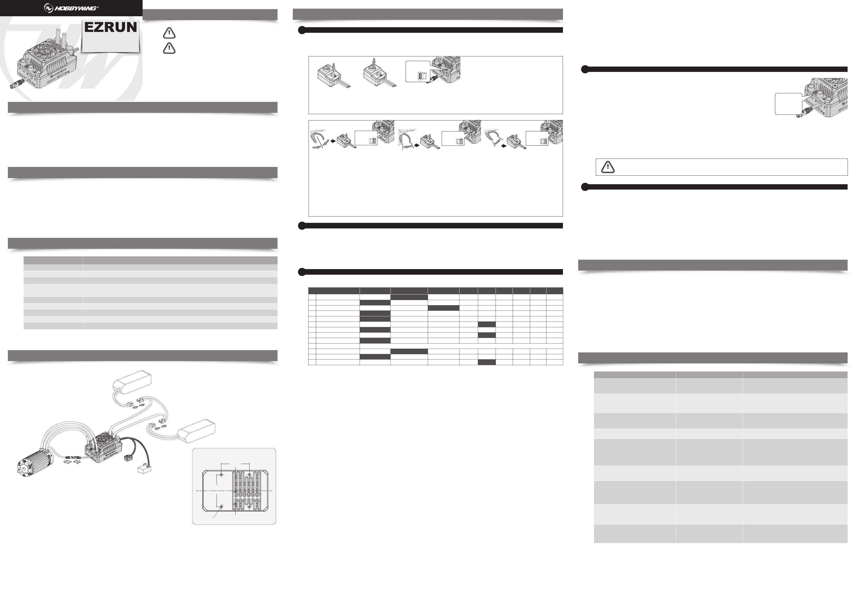
Refer to the wiring instructions and wiring diagram:
1. Motor connection:
There is a difference between connecting a sensored brushless motor and a sensorless brushless motor:
A. When connecting to a sensored brushless motor:
There are strict wire sequencing requirements for connecting the ESC to the motor, the three A/B/C
ESC wires must connect to the three A/B/C motor wires correspondingly, otherwise, it may
damage the ESC. Next, connect the sensor cable of the esc and motor according to the arrow mark
on the sensor connector. If you don’t plug the sensor cable in, your ESC will still work in sensorless
mode even if you’re using a sensored motor.
Note: If the motor direction is reversed, change the parameter on item 4 “Motor rotation direction” to achieve the correct setting.
B. When connecting to a sensorless brushless motor:
There are no wire sequencing requirements needed when using a sensorless brushless motor, you can swap two wires if the motor runs in opposite direction.
2. Recevier connection:
Connect the ESC throttle cable to the throttle channel on the receiver. Since the throttle cable of esc will have BEC voltage output to the receiver and servo, please do
not supply additional power to the receiver, otherwise the esc may be damaged. If additional power is required, disconnect the red wire on the throttle plug from the ESC.
3. Battery connection:
Make sure that the (+) pole of the ESC is connected to the (+) pole of the battery and (-) to the (-). If the connection is reversed, the ESC will be damaged and will not
be covered by the warranty service.
1. Turn on the transmitter, ensure all parameters (D/R, EPA, ATL)
on the throttle channel are at default (100%). For transmitter
without LCD, please turn the knob to the maximum, and the
throttle “TRIM” to 0. (If the transmitter without LCD, turn
the knob to the middle point). You don't need to do this
step if the transmitter's settings are default, and you
can start from the second step directly.
2. Start by turning on the transmitter with the ESC turned off but connected to a battery. Holding the“SET” button then press the “ON/OFF” button, the RED
LED on the ESC starts to flash (The motor beeps at the same time), and then release the “SET” button immediately.
Note : Beeps from the motor may be low sometimes, and you can check the LED status instead.
Hold the SET
button
Press the
ON/OFF
button Release the SET
button once the
LED
flashes.
3. Set the neutral point, the full throttle endpoint and the full brake endpoint.
• Leave transmitter at the neutral position, press the “SET” button, the RED LED dies out and the GREEN LED flashes 1 time and the motor beeps 1 time to accept the
neutral position.
• Pull the throttle trigger to the full throttle position, press the “SET” button, the GREEN LED blinks 2 times and the motor beeps 2 times to accept the full throttle
endpoint.
• Push the throttle trigger to the full brake position, press the “SET” button, the GREEN LED blinks 3 times and the motor beeps 3 times to accept the full brake
endpoint.
Note:
• The end position of forward: Pull the trigger to the maximum throttle position if it is pistol-style transmitter. Push the throttle to the top if it is
board-style transmitter.
• The end position of backward: Push the trigger to the maximum brake position if it is pistol-style transmitter. Pull the throttle to the bottom if it is
board-style transmitter.
4. The motor can be started after the ESC/Radio calibration is complete.
Move the throttle trigger to the neutral
position and press the SET button.
The Green LED flashes
once and motor emits
“Beep” tone.
Move the throttle trigger to the end position
of forward and press the SET button.
The Green LED flashes
twice and motor emits
“Beep-Beep”
tone.
Move the throttle trigger to the end position
of backward and press the SET button.
The Green LED flashes
three times and motor
emits “Beep-
Beep-Beep”
tone.
Switch instructions: short press ON/OFF key to power-on, long press on ON/OFF key to shut down
Power-on beep description: Under normal circumstances, the ESC will emit a few “beep” to indicate the number of lithium cells. A short “beep-” means the #1,
and a long ”beep—“ means the #5. For example: “beep—, beep-”means 6 cells, “beep—, beep-beep-beep-“ means 8 cells,
”beep—beep—“ means 10 cells, ”beep—beep—, beep- beep-“ means 12 cells.
Note: Motor beeping at the same time, the ESC light flashes synchronously. For example: when the motor makes a long beep, the esc flashes for a long time, and
when the motor makes a short beep, the esc flashes for a short time.
Instruction for programmable items
3
The column of white words on black background in the following table are the default values of programmable items.
1. Running Mode:
Option 1: Forward with brake
The vehicle can only move forward and has brake function. This is also commonly acceptable at races.
Option 2: Forward/Reverse and Brake
This option is known to be the “training” mode with “Forward/Reverse with Brake” function. The vehicle only brakes on the first time you push the
throttle trigger to the reverse/brake zone. If the motor stops when the throttle trigger return to the neutral zone and then re-push the trigger to
reverse zone, the vehicle will reverse, if the motor does not completely stop, then your vehicle won’t reverse but still brake, you need to return the
throttle trigger to the neutral zone and push it to reverse zone again. This method is for preventing vehicle from being accidentally reversed.
Option 3: Forward and Reverse
When the throttle trigger is pushed from neutral to reverse point, the motor reverses. This mode is generally used in special vehicles.
2. Lipo Cells:
Set the correct value according to the actual number of Lipo batteries used. The default is automatically calculated.
3. Low Voltage Cut-Off:
This function is mainly to prevent excessive discharge of lithium batteries causing damage. The ESC monitors the battery voltage at all times, and once the
voltage falls below the set threshold, the power output is reduced and the power output is completely cut off after a few seconds. When the voltage protection
is entered, the red LED flashes in the “-, -, -”. The three levels of low, medium and high here correspond to 2.8V/Cell, 3.1V/Cell and 3.4V/Cell respectively. For
NiMH batteries, it is recommended to set this parameter to “Disabled”.
4. Motor Rotation:
Setting the rotation of the motor. Due to some differences with the drivetrains on different car kits, it is possible to that the car will go in the opposite direction
upon full throttle. In the event that this happens, you can set the“motor rotation direction” to the opposite direction; “CW” or “CCW”.
5. BEC Voltage:
BEC voltage support 6V/7.4V/8.4V. Generally, 6.0V is suitable for standard servos, while 7.4V/8.4V is suitable for high-voltage servos. Please set according to the
servo specifications.
WARNING! Do not set the BEC voltage above the maximum operating voltage of the servo, as this may damage the servo or even the ESC.
6. Max. Brake Force:
This ESC provides proportional braking function; the braking effect is decided by the position of the throttle trigger. It sets the percentage of available braking
power when full brake is applied. Large amount will shorten the braking time but it may damage your pinion and spur gear.
7. Max. Reverse Force:
Refers to the reversing speed. Selecting different parameter values can produce different reversing speed. It is recommended to use a smaller reversing speed to
avoid errors caused by reversing too quickly.
8. Punch:
Set in 1-9 stages, the higher the set value, the faster the acceleration. Kindly take into consideration according to the site, tire grip characteristics, vehicle
configuration, etc. An aggressive setting may cause the tire to slip, the starting current to be too large and adversely affect the electronics performace.
9. Drag Brake Force:
Refers to the brake force generated by the motor when the throttle trigger returns to neutral position. Choose the appropriate value according to the type of
vehicle, configuration, site, etc.Due to different devices for setting this esc, there are two different display contents, as follows:
When the LED program box is used, there are 8 option values for the drag brake force that can be adjusted, see the row of “Drag Brake Force (LED Box)” in the
above table.
When using LCD program box or OTA Bluetooth module, the drag brake force is 0-100% adjustable, and the adjust step is 1%, see the row of " Drag Brake
Force (LCD Box / OTA)" in the above table.
10. Initial Throttle Force:
It also called as minimum throttle force. You can set it according to wheel tire and traction. If the ground is slippery, please set a small throttle force.
11. Turbo Timing:
The Turbo timing can additionally increase the motor rpm.It will initiate at full throttle. It is usually used on a long straight road to release the maximum power
of the motor. The higher this value is, the more the rpm of the motor will increase, and the greater the running current will be, the higher the temperature of
the motor and esc. Therefore, please set this value reasonably.
12. Turbo Delay:
When “TURBO DELAY” is set to “INSTANT”, the Turbo Timing will be activated right after the throttle trigger is moved to the full throttle position. When other
value(s) is applied, you will need to hold the throttle trigger at the full throttle position (as you set) till the Turbo Timing initiates.
Option 1
Running Mode
Lipo Cells
Cutoff Voltage
Motor Rotation
BEC Voltage
Max.Brake Force
Max.Reverse Force
Punch
Drag Brake Force(LED Box)
Drag Brake Force(LCD Box / OTA)
Initial Throttle Force
Turbo Timing
Turbo Delay
0-100%(Adjust Step 1%), Default 0%.
1
2
3
4
5
6
7
8
9
9
10
11
12
Option 2 Option 3 Option 4 Option 5 Option 6 Option 7 Option 8 Option 9
7S
40%
4%
16°
8S 9S 10S 11S 12S
Auto (high)
50%
100%
Level 4
20%
3%
12°
0.15s
87.50%
Level 7
80%
6%
24°
0.5s
100%
Level 8
100%
7%
0.7s
Disabled
Level 9
8%
1.0s
Item
Forward / Reverse with Brake
1%
Auto (medium)
Level 5
62.50%
0.2s
Auto
CCW
6.0V
25%
0%
0°
8.4V
37.50%
75%
Level 3
10%
2%
8°
0.1s
Forward with brake Forward with reverse
12.50%
Disabled
Level 1
0.5%
Instant
6S
Auto (low)
CW
7.4V
25%
50%
Level 2
5%
4°
0.05s
75%
Level 6
60%
5%
20°
0.3s
1. The LED program card is used to set the parameters:
Connect the program card to the ESC and power up. Using the “ITEM” and “VALUE” buttons on the program
card to quickly select and change the values. Press “OK” to save the parameters.
2. The LCD G2 program box is used to set the parameters:
You can program this ESC via a multifunction LCD G2 program box or via a multifunction LCD G2 program box
& a PC (HOBBYWING USB LINK software needs to be installed on the PC). Before programming, you need to
connect your ESC and the LCD G2 program box via a cable with two JR male connectors and turn on the ESC;
Press any button on the program box to initiate the communication between your ESC and the program box.
Seconds later,you can adjust the setting via“ITEM” & “VALUE” buttons, and press the “OK” button to save new
settings to your ESC.
3. The OTA Bluetooth module is used to set the parameters:
Attach the OTA Bluetooth module to the ESC, and install the HOBBYWING HW LINK app on your phone for parameter settings.
4. View the ESC data after running:
After connecting the OTA Bluetooth module to the esc and establishing communication, You can view the real-time running data in the [Data Log] menu in HW link app.
This independent
programming port
for connecting LED/
LCD program box/
OTA programmer.
The program box needs to be connected to the independent programming port. Otherwise, it will not work!
ATTENTION
Troubles SolutionPossible Causes
1. The battery voltage is not output to the ESC;
2. The switch is damaged.
The battery pack voltage is not within the
range of support.
1. The throttle signal is not detected by the ESC;
2. The neutral point of the ESC is not calibrated
correctly.
The transmission on the car kit is different
1. Possible interference;
2. The ESC enters into low-voltage protection
state;
3. The ESC enters into overheat protection state.
1. The neutral point of the remote control
throttle channel deviates from the brake area;
2. The parameter item "Runnig Mode" is set
incorrectly;
3. The ESC is damaged.
1. The motor is connected incorrectly;
2. ESC fault (partial power pipe MOSFET
burned out).
1. Check the battery,and whether the connection between battery and
esc is good and whether the plug is soldered well;
2. Replace the switch.
Check the battery voltage or change the battery for test.
1. Check if the throttle wire is plugged into the correct channel. Check if
your transmitter is turned on. Check if the receiver ok.
2. Recalibrate the throttle travel.
Set the parameter item “Motor Rotation” to the opposite direction.
1. Check the cause of the interference in the receiver and check the
battery level of the transmitter;
2. Replace the battery if red light keeps flashing;
3. The green light continues to flash for temperature protection, please
continue to use after the ESC or motor temperature is reduced (it is
recommended to reduce the load on the vehicle).
1. Recalibrate the esc,when the throttle trigger is at the neutral point,
the esc lights are off;
2. The parameter item “Runnig Mode” is set to incorrectly;
3. Contact the distributor to handle the repair.
1. Check the plugs and the solder points and whether the sequence of A,
B and C wires is correct.;
2. Contact the dealer to handle the repair.
Connect the program box with the correct interface, which to the
independent programming port, not throttle cable.
1. Check whether the throttle cable is correctly connected to the receiver.
2. If the servo works normally,you can connect the throttle cable of esc to
the steering channel to have a test, or change the transmitter/receiver
system for test directly.
The motor does not start after power-up, with a “beep-
beep-, beep-beep-” warning tone accompanied by a
flashing red light (approximately 0.5 seconds for each set
of two-tone intervals)
After power on, the red light flashes quickly
The light does not turn on after power-up, the motor
does not start, and the fan does not work
The car is going in the reversed direction when the
forward throttle is applied
The motor stuttered and unable to start.
Going forward normally, but not reverse.
LED displays three end horizontal lines all the time
— — — when connecting LED program card; Or
displays “Connecting ESC” when connecting LCD
program box.
The throttle travel setting could not be completed.
The motor suddenly stopped or significantly reduced the
output in running.
The program box is connected incorrectly to
the ESC.
The ESC did not receive the correct throttle
signal.
USER MANUAL
EZRUN MAX5 HV G2
Brushless Electronic Speed Controller
Battery
Battery
Switch
Receiver
Receiver
Motor
Electronic Speed Controller
Mounting Hole Template