
SecurView® DX/RT Workstation
User Guide
MAN-07257-001 Revision 002


SecurView
®
DX/RT
Breast Imaging Workstation
User Guide
For Software Version 11.0
Part Number MAN-07257-001
Revision 002
July 2021

© 2020-2021 Hologic, Inc. Printed in the USA. This manual was originally written in English.
Hologic, Cenova, C-View, EmphaSize, Genius AI, ImageChecker, Intelligent 2D, LesionMetrics, Mammography Prior
Enhancement, MultiView, PeerView, Quantra, RightOn, SecurView, Selenia, TechMate and associated logos are trademarks
and/or registered trademarks of Hologic, Inc., and/or its subsidiaries in the United States and/or other countries. All other
trademarks, registered trademarks, and product names are the property of their respective owners.
This product may be protected by one or more U.S. or foreign patents as identified at www.Hologic.com/patent-information.
Softcopy reading software © 2002–2020 MeVis Medical Solutions AG. All rights reserved. This product and related
documentation are protected by copyright and are distributed under licenses restricting their use, copying, distribution, and
decompilation. No part of this product or related documentation may be reproduced in any form by any means without prior
written authorization of MeVis Medical Solutions AG and its licensors, if any. FlowBack, FlowNext, MammoNavigator, and
ReportFlow are trademarks of MeVis BreastCare GmbH & Co. KG. This product may be protected by one or more of the
following patents: 7,283,857, 6,891,920.
Libraries
Libtiff library © 1988-1997 Sam Leffler, 1991-1997 Silicon Graphics, Inc. OFFIS_DCMTK © 1994–2005, OFFIS MergeCOM-3
Advanced Integrator's Tool Kit – Version 5.6.0 PostgreSQL – Version 11.2.1 Portions Copyright © 1996-2019, The PostgreSQL
Global Development Group, Portions Copyright © 1994, The Regents of the University of California jpeglib © 1991-1998,
Thomas G. Lane xerces © 1999-2010 The Apache Software Foundation 7-Zip © 1999-2009 Igor Pavlov Qt 4.8.6 © 2014 Digia
Plc and/or its subsidiary(-ies), licensed under LGPL v2.1. This Qt library has been adapted by MeVis Medical Solutions AG. You
may obtain the complete corresponding source code by sending an order to MeVis Medical Solutions AG, Support Department,
Caroline-Herschel-Str. 1, 28359 Bremen, Germany.
Product Support
USA: +1.877.371.4372
Europe: +32 2 711 4690
Asia: +852 37487700
Australia: +1 800 264 073
All Other: +1 781 999 7750
Email: BreastHealth.Support@hologic.com

SecurView DX-RT 11.0 Workstation User Guide
Table of Contents
MAN-07257-001 Revision 002 v
Table of Contents
List of Figures _________________________________________________________________ xi
List of Tables _________________________________________________________________ xv
1: Introduction __________________________________________________________________1
1.1 Overview .................................................................................................................................................................. 1
1.2 Intended Use............................................................................................................................................................ 2
1.2.1 SecurView DX Diagnostic Workstation Intended Use ........................................................................ 2
1.2.2 SecurView RT Technologist Workstation Intended Use ..................................................................... 2
1.3 Using This Guide .................................................................................................................................................... 2
1.4 Resources Available................................................................................................................................................ 3
1.5 Warnings and Precautions ..................................................................................................................................... 4
1.5.1 System Operation ..................................................................................................................................... 4
1.5.2 Installation and Maintenance .................................................................................................................. 6
1.6 Product Complaints ................................................................................................................................................ 7
1.7 Warranty Statement ................................................................................................................................................ 7
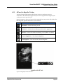
2: Workstation Description _______________________________________________________9
2.1 Workstation Overview ........................................................................................................................................... 9
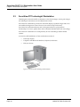
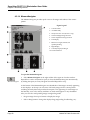
2.2 SecurView DX Diagnostic Workstation ............................................................................................................. 10
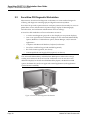
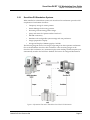
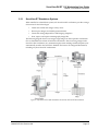
2.2.1 SecurView DX Standalone Systems ..................................................................................................... 11
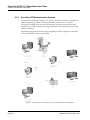
2.2.2 SecurView DX Multiworkstation Systems .......................................................................................... 12
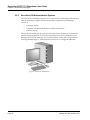
2.3 SecurView RT Technologist Workstation .......................................................................................................... 14
2.3.1 SecurView RT Standalone Systems ...................................................................................................... 15
2.3.2 SecurView RT Multiworkstation Systems ........................................................................................... 16
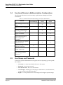
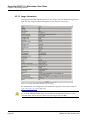
2.4 Functional Division in Multiworkstation Configurations ............................................................................... 18
2.5 User Groups and Passwords ............................................................................................................................... 18
2.6 Startup and Shutdown ......................................................................................................................................... 20
2.7 Logging into SecurView ....................................................................................................................................... 21
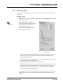
2.8 Accessing Unique Device Identifier Information ............................................................................................. 22
3: Patient Manager _____________________________________________________________23
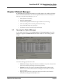
3.1 Opening the Patient Manager ............................................................................................................................. 23
3.2 Using the Patient List ........................................................................................................................................... 24
3.2.1 Selecting Patients .................................................................................................................................... 24
3.2.2 Patient List Buttons ................................................................................................................................ 25
3.2.3 Patient List Columns .............................................................................................................................. 26
3.2.4 Reading States ......................................................................................................................................... 28
3.2.5 Auto-Fetching Patient Data ................................................................................................................... 29
3.2.6 Using the Shortcut Menu ....................................................................................................................... 30
3.2.7 Merging Patient Data ............................................................................................................................. 30
3.2.8 Searching for Patients ............................................................................................................................ 32

SecurView DX-RT 11.0 Workstation User Guide
Table of Contents
vi MAN-07257-001 Revision 002
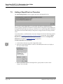
3.3 Creating Sessions .................................................................................................................................................. 34
3.4 Importing DICOM Images ................................................................................................................................... 35
3.5 Synchronizing Patient List with MultiView ...................................................................................................... 36
4: Reviewing Patients ___________________________________________________________37
4.1 Displaying Patient Studies ................................................................................................................................... 37
4.1.1 Patient List Worklists ............................................................................................................................. 37
4.1.2 Automatically Generated Worklists ..................................................................................................... 38
4.1.3 Session Worklists .................................................................................................................................... 39
4.1.4 MG Viewer .............................................................................................................................................. 40
4.2 Displaying Patient Images ................................................................................................................................... 41
4.2.1 Navigating Patients ................................................................................................................................ 42
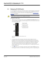
4.2.2 Using the Keypad ................................................................................................................................... 43
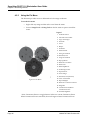
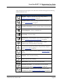
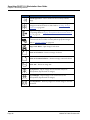
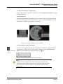
4.2.3 Using the Pie Menu ................................................................................................................................ 44
4.2.4 Using a ReportFlow ................................................................................................................................ 47
4.2.5 Patient Reading and Lock States During Review ............................................................................... 47
4.2.6 Panning Images ....................................................................................................................................... 48
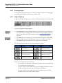
4.2.7 Image Hangings ...................................................................................................................................... 48
4.2.8 Temporary Single Tiling Mode ............................................................................................................. 49
4.2.9 Intelligent Roaming ................................................................................................................................ 50
4.2.10 Scaling Modes ......................................................................................................................................... 52
4.2.11 Pixel Meter ............................................................................................................................................... 53
4.2.12 Stack and Timepoint Indicators ............................................................................................................ 54
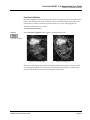
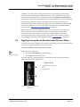
4.2.13 Working with Ultrasound Images ........................................................................................................ 55
4.2.14 MammoNavigator .................................................................................................................................. 58
4.2.15 Image Information .................................................................................................................................. 60
4.2.16 Patient Information Overlays ................................................................................................................ 61
4.2.17 MG Secondary Captures and MM ScreenCaptures ........................................................................... 63
4.3 Visualizing Image Details .................................................................................................................................... 63
4.3.1 Magnifier and Inverted Magnifier ........................................................................................................ 65
4.3.2 AIE and the Magnifier Toolbar ............................................................................................................. 67
4.3.3 Continuous Zoom ................................................................................................................................... 68
4.3.4 Window/Level and Gamma Adjustments........................................................................................... 69
4.3.5 Applying VOI LUTs ............................................................................................................................... 71
4.3.6 MPE Images ............................................................................................................................................. 72
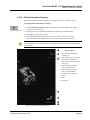
4.3.7 DICOM 6000 Overlays ........................................................................................................................... 73
4.3.8 CLAHE Image Enhancement ................................................................................................................ 75
4.4 Using CAD ............................................................................................................................................................. 75
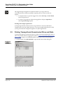
4.4.1 Displaying CAD Information ................................................................................................................ 75
4.4.2 Hologic CAD ........................................................................................................................................... 76
4.4.3 Hologic Imaging Biomarkers ................................................................................................................ 81
4.4.4 Switching Between Multiple Mammography CAD SRs ................................................................... 82
4.5 Creating and Viewing Annotations .................................................................................................................... 82
4.5.1 Marking an Image ................................................................................................................................... 83
4.5.2 Describing a Region of Interest ............................................................................................................. 85

SecurView DX-RT 11.0 Workstation User Guide
Table of Contents
MAN-07257-001 Revision 002 vii
4.5.3 Viewing Annotations ............................................................................................................................. 86
4.6 Sending and Viewing Notices ............................................................................................................................. 88
4.6.1 Sending Notices ...................................................................................................................................... 88
4.6.2 Viewing Notices ...................................................................................................................................... 89
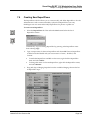
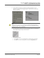
4.7 Closing a Study ..................................................................................................................................................... 90
4.7.1 Closing a Study as a Radiologist .......................................................................................................... 90
4.7.2 Closing a Study as a Technologist ........................................................................................................ 92
4.7.3 Closing a Study from an External Application ................................................................................... 93
4.8 Printing Options .................................................................................................................................................... 93
4.9 Patient Synchronization with an External Application ................................................................................... 96
4.9.1 Manual Synchronization ....................................................................................................................... 96
4.9.2 Automatic Synchronization .................................................................................................................. 96
4.9.3 Synchronization When You Receive a Message ................................................................................. 97
5: Working with Tomosynthesis Images __________________________________________99
5.1 Overview of Tomosynthesis Imaging ................................................................................................................ 99
5.2 Navigating Tomosynthesis Images .................................................................................................................. 101
5.2.1 Tomosynthesis Navigation Buttons ................................................................................................... 101
5.2.2 Viewing Tomosynthesis Slices or Slabs ............................................................................................. 102
5.2.3 Changing Slab Thickness ..................................................................................................................... 103
5.2.4 Annotating a Tomosynthesis Image .................................................................................................. 104
5.2.5 Using Cine Mode .................................................................................................................................. 105
5.2.6 Using Local Cine Mode ....................................................................................................................... 106
5.2.7 Smart Mapping ..................................................................................................................................... 106
5.2.8 Scrolling Through Linked Tiles .......................................................................................................... 108
5.2.9 Exporting a Movie ................................................................................................................................ 109
5.3 Displaying 3D CAD Results .............................................................................................................................. 110
5.4 Tagging Tomosynthesis Reconstructed Slices or Slabs ................................................................................. 111
5.5 Printing Tomosynthesis Reconstructed Slices and Slabs ............................................................................... 112
6: Setting User Preferences _____________________________________________________115
6.1 Workflow Preferences ........................................................................................................................................ 116
6.2 Image Presentation Preferences ........................................................................................................................ 118
6.3 Tools and Overlays Preferences ........................................................................................................................ 120
6.4 User Profile Preferences ..................................................................................................................................... 124
7: Hanging Snapshots and ReportFlows _________________________________________127
7.1 Viewing ReportFlows ......................................................................................................................................... 127
7.2 Viewing Hanging Snapshots ............................................................................................................................. 128
7.3 Creating and Modifying Hanging Snapshots ................................................................................................. 129
7.3.1 Creating New Hanging Snapshots ..................................................................................................... 130
7.3.2 Copying and Editing a Hanging Snapshot ....................................................................................... 134
7.3.3 Renaming a Hanging Snapshot .......................................................................................................... 134
7.3.4 Changing a Hanging Snapshot Icon .................................................................................................. 135

SecurView DX-RT 11.0 Workstation User Guide
Table of Contents
viii MAN-07257-001 Revision 002
7.4 ReportFlows ......................................................................................................................................................... 136
7.5 Linking a ReportFlow to a Procedure .............................................................................................................. 138
7.6 Creating New ReportFlows ............................................................................................................................... 139
7.7 ReportFlows Preferences .................................................................................................................................... 142
7.7.1 Workflow Selection .............................................................................................................................. 142
7.7.2 Overview Hanging Configuration ..................................................................................................... 143
8: Administrator Tasks _________________________________________________________145
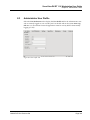
8.1 Opening the Administration Module .............................................................................................................. 145
8.2 Managing User Profiles ...................................................................................................................................... 146
8.3 Administrator User Profile ................................................................................................................................ 149
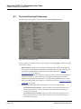
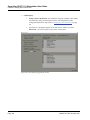
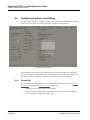
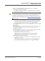
8.4 Configuring System-Level Settings .................................................................................................................. 150
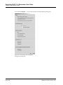
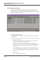
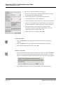
8.4.1 Scheduling ............................................................................................................................................. 150
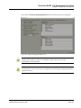
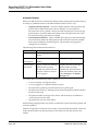
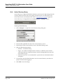
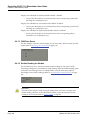
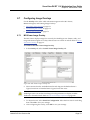
8.4.2 Disk Space Monitoring and Auto-Deletion ....................................................................................... 151
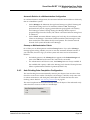
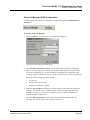
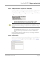
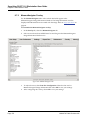
8.4.3 Auto-Fetching/Auto-Completion Configuration ............................................................................. 153
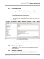
8.4.4 Active Directory Setup ......................................................................................................................... 156
8.4.5 Study List Manager (SLM) Configuration ......................................................................................... 157
8.4.6 Application Event Logging ................................................................................................................. 158
8.4.7 UnifiTM Analytics ................................................................................................................................... 160
8.4.8 Search on PACS..................................................................................................................................... 161
8.4.9 Configure Synchronization Interface ................................................................................................. 161
8.4.10 Worklists ................................................................................................................................................ 163
8.4.11 Date/Time Format and Units .............................................................................................................. 163
8.4.12 Multimodality Viewer .......................................................................................................................... 163
8.4.13 Manufacturer Settings .......................................................................................................................... 164
8.4.14 CAD/Case Score .................................................................................................................................... 166
8.4.15 Double Reading for Studies ................................................................................................................ 166
8.4.16 Sending Annotations, Tagged Tomo, Study State ........................................................................... 167
8.4.17 Local Institution .................................................................................................................................... 167
8.4.18 Secondary Capture ............................................................................................................................... 168
8.4.19 Adoption of Institution Name and Address ..................................................................................... 168
8.5 Configuring System-Level Hanging Snapshots and ReportFlows .............................................................. 168
8.5.1 Current–Prior Time Range .................................................................................................................. 169
8.6 Configuring Examination Procedure Names .................................................................................................. 169
8.7 Configuring Image Overlays ............................................................................................................................. 171
8.7.1 MG Viewer Image Overlay ................................................................................................................. 171
8.7.2 MammoNavigator Overlay ................................................................................................................. 172
8.7.3 Printing Image Overlay ....................................................................................................................... 173
8.8 Maintaining the Database .................................................................................................................................. 173
8.8.1 Backing Up the Database ..................................................................................................................... 173
8.8.2 Scheduling Database Maintenance .................................................................................................... 175
8.8.3 Clusterwide Log File Collection ......................................................................................................... 175

SecurView DX-RT 11.0 Workstation User Guide
Table of Contents
MAN-07257-001 Revision 002 ix
9: Case Administrator Tasks ____________________________________________________177
9.1 Opening the Administration Module .............................................................................................................. 177
9.2 Deleting Patients ................................................................................................................................................. 178
10: Patient and ReportFlow Files ________________________________________________179
10.1 Exporting Currently Displayed Image Files ................................................................................................... 179
10.2 Exporting DICOM Files ..................................................................................................................................... 180
10.3 Importing and Exporting ReportFlows ........................................................................................................... 182
10.3.1 Importing ReportFlows from a USB drive to SecurView ................................................................ 182
10.3.2 Exporting ReportFlows from SecurView to a USB Drive ............................................................... 182
Appendix A Keyboard Shortcuts ________________________________________________183
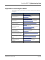
Appendix B Technologist’s Guide ______________________________________________185
Index ________________________________________________________________________187


SecurView DX-RT 11.0 Workstation User Guide
Table of Contents
MAN-07257-001 Revision 002 xi
List of Figures
Figure 1: SecurView DX Diagnostic Workstation ....................................................................................................... 10
Figure 2: Information Flow with a Standalone SecurView DX Workstation........................................................... 11
Figure 3: SecurView DX Manager ................................................................................................................................. 12
Figure 4: Information Flow in a SecurView DX Multiworkstation System ............................................................. 13
Figure 5: SecurView RT Technologist Workstation .................................................................................................... 14
Figure 6: Information Flow with Standalone SecurView DX and RT Workstations .............................................. 15
Figure 7: Image Flow in a SecurView DX and RT Multiworkstation Installation .................................................. 16
Figure 8: Physician Annotations Flow in a SecurView DX and RT MultiWorkstation Installation ..................... 17
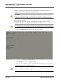
Figure 9: Login Window ................................................................................................................................................. 20
Figure 10: Shutdown Message ....................................................................................................................................... 20
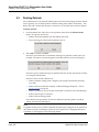
Figure 11: Startup Screen ................................................................................................................................................ 21
Figure 12: Patient List ...................................................................................................................................................... 23
Figure 13: Example Studies and Associated Image Series ......................................................................................... 24
Figure 14: Patient List Buttons ....................................................................................................................................... 25
Figure 15: Patient List Search Buttons ........................................................................................................................... 26
Figure 16: Select Primary Patient Dialog Box .............................................................................................................. 31
Figure 17: Local Search Criteria ..................................................................................................................................... 32
Figure 18: PACS Search Criteria .................................................................................................................................... 33
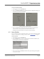
Figure 19: Sessions Tab ................................................................................................................................................... 34
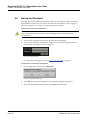
Figure 20: Bar Code Scanner .......................................................................................................................................... 37
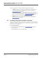
Figure 21: Worklist Section Combined RTI .................................................................................................................. 38
Figure 22: Automatic Worklists Buttons....................................................................................................................... 39
Figure 23: Example List of Sessions .............................................................................................................................. 39
Figure 24: MG Viewer – Left Display ............................................................................................................................ 40
Figure 25: MG Viewer – Right Display ......................................................................................................................... 40
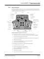
Figure 26: SecurView DX Keypad ................................................................................................................................. 43
Figure 27: Pie Menu ......................................................................................................................................................... 44
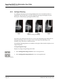
Figure 28: Predefined Image Hangings ........................................................................................................................ 48
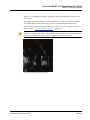
Figure 29: Intelligent Roaming ....................................................................................................................................... 50
Figure 30: Intelligent Roaming Indicator ...................................................................................................................... 51
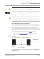
Figure 31: Pixel Meters .................................................................................................................................................... 53
Figure 32: Pixel Meters with White Background Indicating Interpolated Pixel Values ........................................ 54
Figure 33: Stack Indicator ............................................................................................................................................... 54
Figure 34: Stack & Timepoint Indicators ...................................................................................................................... 54
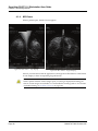
Figure 35: Ultrasound Image Navigation ..................................................................................................................... 56
Figure 36: Ultrasound Multi-frame Image Navigation .............................................................................................. 57
Figure 37: Example DICOM Information for an Image .............................................................................................. 60
Figure 38: Patient Information Overlays ...................................................................................................................... 61
Figure 39: Image Evaluation Tools ................................................................................................................................ 63
Figure 40: Magnifier ........................................................................................................................................................ 66
Figure 41: Inverted Magnifier ........................................................................................................................................ 66
Figure 42: Magnifier and AIE Toolbar .......................................................................................................................... 67

SecurView DX-RT 11.0 Workstation User Guide
Table of Contents
xii MAN-07257-001 Revision 002
Figure 43: Window Level Dialog Box ........................................................................................................................... 70
Figure 44: Example List of VOI LUT ............................................................................................................................. 71
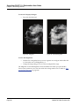
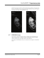
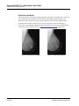
Figure 45: Without MPE Processing .............................................................................................................................. 73
Figure 46: With MPE Processing .................................................................................................................................... 73
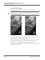
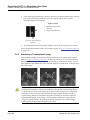
Figure 47: Original Image ............................................................................................................................................... 74
Figure 48: Image with DICOM 6000 Overlay ............................................................................................................... 74
Figure 49: ImageChecker CAD and Genius AI Detection Overlay ........................................................................... 77
Figure 50: ImageChecker CAD failed for the image ................................................................................................... 77
Figure 51: CAD without EmphaSize ............................................................................................................................. 78
Figure 52: CAD with EmphaSize ................................................................................................................................... 78
Figure 53: PeerView Off .................................................................................................................................................. 79
Figure 54: PeerView On .................................................................................................................................................. 79
Figure 55: Hologic Imaging Biomarkers Per Subject and Per Breast Tabs ............................................................... 81
Figure 56: Example CAD SR List ................................................................................................................................... 82
Figure 57: Freehand ......................................................................................................................................................... 83
Figure 58: Ellipse .............................................................................................................................................................. 83
Figure 59: Arrow .............................................................................................................................................................. 83
Figure 60: Measurement.................................................................................................................................................. 83
Figure 61: Ruler ................................................................................................................................................................ 84
Figure 62: Annotation Dialog Box ................................................................................................................................. 85
Figure 63: Example Annotations .................................................................................................................................... 86
Figure 64: Selecting a Reviewer from the Pie Menu.................................................................................................... 87
Figure 65: Example Third-party GSPS Annotation Indicator .................................................................................... 87
Figure 66: Send All Notices Submenu ........................................................................................................................... 88
Figure 67: Send Image Notice Submenu ....................................................................................................................... 89
Figure 68: Close Study Message for Patients with Received Notices ....................................................................... 93
Figure 69: MG Viewer Print Dialog Box ....................................................................................................................... 95
Figure 70: Tomosynthesis: Reconstructed Slices (schematic representation) .......................................................... 99
Figure 71: Tomosynthesis Navigation Buttons .......................................................................................................... 101
Figure 72: Slider Tool..................................................................................................................................................... 102
Figure 73: V-Split Cursor .............................................................................................................................................. 103
Figure 74: Slab Thickness Indicator ............................................................................................................................. 104
Figure 75: Cine Button and Speed Control Slider...................................................................................................... 106
Figure 76: Export Tomosynthesis Movie Dialog Box ................................................................................................ 109
Figure 77: Tomosynthesis Slider with 3D CAD Indicators ...................................................................................... 110
Figure 78: Slider Tool with Tag Indicators ................................................................................................................. 111
Figure 79: MG Viewer Print Dialog Box ..................................................................................................................... 112
Figure 80: User Preferences Workflow Tab (partial view) ....................................................................................... 115
Figure 81: Workflow Tab .............................................................................................................................................. 116
Figure 82: Read Time Mix Configuration ................................................................................................................... 116
Figure 83: Image Presentation Tab .............................................................................................................................. 118
Figure 84: Tools and Overlays Tab .............................................................................................................................. 120
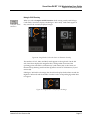
Figure 85: CAD Display Configuration Screen .......................................................................................................... 122
Figure 86: –Hologic Imaging Biomarkers Tab ........................................................................................................... 123
Figure 87: User Profile Tab ........................................................................................................................................... 124

SecurView DX-RT 11.0 Workstation User Guide
Table of Contents
MAN-07257-001 Revision 002 xiii
Figure 88: ReportFlows Tab ......................................................................................................................................... 127
Figure 89: Hanging Snapshots Tab .............................................................................................................................. 128
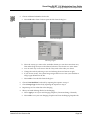
Figure 90: Selected Tile Region .................................................................................................................................... 131
Figure 91: Example ReportFlow (partial view) .......................................................................................................... 136
Figure 92: User Setup Tab ............................................................................................................................................. 145
Figure 93: User Setup Buttons ...................................................................................................................................... 146
Figure 94: New User Dialog Box ................................................................................................................................. 147
Figure 95: User Profile Tab ........................................................................................................................................... 149
Figure 96: Settings Window ......................................................................................................................................... 150
Figure 97: Disk Space Monitoring and Auto-Deletion Settings .............................................................................. 151
Figure 98: Auto-Fetching/Auto-Completion Configuration Dialog Box ................................................................ 154
Figure 99: Active Directory Setup Dialog Box ........................................................................................................... 156
Figure 100: SLM Configuration Dialog Box ............................................................................................................... 157
Figure 101: Synchronization Interface Configuration Dialog Box .......................................................................... 162
Figure 102: Manufacturer Settings Dialog Box .......................................................................................................... 164
Figure 103: Examination Procedure Identification Window ................................................................................... 169
Figure 104: MG Viewer Image Overlay Tab .............................................................................................................. 171
Figure 105: MammoNavigator Tab ............................................................................................................................. 172
Figure 106: Printing Image Overlay Tab..................................................................................................................... 173
Figure 107: Maintenance Tab ....................................................................................................................................... 174
Figure 108: Windows Dialog Box for CD/DVD Write Mode ................................................................................... 181


SecurView DX-RT 11.0 Workstation User Guide
Table of Contents
MAN-07257-001 Revision 002 xv
List of Tables
Table 1: Functional Division Between Manager and Client Workstations .............................................................. 18
Table 2: User Groups and Rights ................................................................................................................................... 19
Table 3: Reading State Definitions ................................................................................................................................. 29


SecurView DX-RT 11.0 Workstation User Guide
Chapter 1: Introduction
MAN-07257-001 Revision 002 Page 1
1: Introduction
This chapter provides an overview of Hologic SecurView® DX and RT workstations, with
information about this guide, product support resources, and safety precautions.
1.1 Overview
This guide provides instructions for operating the SecurView workstations:
• SecurView DX Diagnostic Workstation
• SecurView RT Technologist Workstation
In addition, this guide provides instructions for working with the following
supplemental Hologic software applications:
• ImageChecker® Computer Aided Detection
• Quantra™ Breast Density Assessment
• Application Synchronization
• Study List Manager
For information regarding the Advanced Multimodality Option, refer to the SecurView
Advanced Multimodality Option User Guide.
SecurView workstations provide a dedicated softcopy review environment for diagnostic
and screening mammography. The system user interface and workflow are optimized to
support experienced mammography reviewers in high-volume reading. Efficiency and
reading quality are supported by specialized features including:
• Predefined Hanging Snapshots
• Best matching ReportFlow
• Workflow keypad
• Patient Bar Code Scanner
• Individual user login and user preference settings
• Automatically generated worklists
• Predefined standard views
• Support for double reading
SecurView provides access to additional patient data:
• MammoNavigator to support easy access to non-standardized image material
such as additional views, mosaics, and scanned documents
• Mammography CAD Structured Report (CAD SR) integration
• Automatic synchronization with external applications
• Application event logging to support compliance with patient privacy policies
• Study List Manager adds non-local patients to patient list to facilitate automatic
synchronization
Chapter 1

SecurView DX-RT 11.0 Workstation User Guide
Chapter 1: Introduction
Page 2 MAN-07257-001 Revision 002
1.2 Intended Use
United States federal law restricts this device to use by, or on the order of, a physician.
1.2.1 SecurView DX Diagnostic Workstation Intended Use
The Hologic SecurView DX device is intended for selection, display, manipulation,
filming, and media interchange of multimodality images from a variety of different
modality systems. It also interfaces to various image storage and printing devices using
DICOM or similar interface standards. The device used with FDA-cleared monitors may
be used by a trained physician for display, manipulation and interpretation of lossless
compressed or non-compressed mammographic images for screening and diagnostic
mammography and digital breast tomosynthesis, as well as any other DICOM
multimodality image. SecurView DX is typically used by trained professionals,
including, but not limited to physicians, radiologists, nurses, medical technicians and
assistants.
1.2.2 SecurView RT Technologist Workstation Intended Use
The SecurView RT Technologist Workstation is a softcopy display system intended for
viewing only and does not support diagnostic reading of mammography. It is capable of
retrieving prior mammography images for display from PACS and other DICOM image
storage systems.
1.3 Using This Guide
This guide is organized as follows:
• Introduction provides background information on the system and the guides.
• Workstation Description provides an overview of the SecurView workstations,
including component descriptions. It also explains how to start up and shut
down the system, and how to log in.
• Patient Manager explains the Patient List, which includes all patients, studies,
and images currently in the SecurView database. The chapter also explains how
to set up reviewing Sessions.
• Reviewing Patients describes how to open patients for viewing, how to use the
viewing and annotation tools, how to close studies, and printing options.
• Working with Tomosynthesis Images describes how to view and work with
tomosynthesis images.
• Setting User Preferences explains how to define preferences for individual users.
• Hanging Snapshots and ReportFlows describes Hanging Snapshots and
ReportFlows, how a Radiologist user can select specific ReportFlows for
everyday use, and how to create new Hanging Snapshots and ReportFlows.

SecurView DX-RT 11.0 Workstation User Guide
Chapter 1: Introduction
MAN-07257-001 Revision 002 Page 3
• Administrator Tasks describes system administrator tasks such as managing
users, configuring system-level settings, and backing up the patient database.
• Case Administrator Tasks describes how the case administrator can delete
patient data.
• Patient and ReportFlow Files provides procedures intended to support the
technologist in managing patient and ReportFlow files.
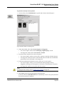
1.4 Resources Available
In addition to this guide, the following resources are available to assist you when
working with SecurView workstations.
• Training: For new systems, the Hologic Applications team provides remote in-depth
training for radiologists and technologists. For additional personalized instruction,
contact your Hologic representative.
• Hologic Training Center: This website provides quick access to guides and training
materials for Hologic products and is available at no charge to our customers under
warranty or Hologic service contract. You can find the Training Center by visiting
the Hologic website (www.hologic.com).
• Additional Documentation: In addition to this guide, Hologic supplies the following
documents for the SecurView workstations:
• SecurView DX/RT Workstation Release Notes
• SecurView DX Workstation Quality Control Manual
• SecurView DX/RT Workstation Installation & Service Manual
• SecurView Workstation DICOM Conformance Statements
• SecurView Advanced Multimodality Option User Guide
• SecurView Advanced Multimodality Option Installation & Service Manual
The SecurView User Guide and Advanced Multimodality Option User Guide are
available online by selecting the Help icon on the SecurView workstation toolbar.
You can obtain additional copies of printed guides and manuals through your
Hologic representative. The DICOM Conformance Statements are available at
www.hologic.com.
• Product Support and Service: For information, refer to the copyright page of this
guide.

SecurView DX-RT 11.0 Workstation User Guide
Chapter 1: Introduction
Page 4 MAN-07257-001 Revision 002
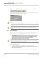
1.5 Warnings and Precautions
This guide uses the following conventions to provide technical and safety information of
special interest.
Warning:
An instruction that, if not followed, can result in a hazardous condition.
Caution
An instruction that, if not followed, can result in damage to the system.
Important
An instruction provided to ensure correct results and optimal performance, or to clarify
limitations of the device.
Note
Information provided to clarify a particular step or procedure.
Before using the system, read the following warnings and precautions.
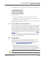
1.5.1 System Operation
Warning:
The system is intended for use only by personnel who have read this guide
and received training on how to use the system. Hologic does not accept
responsibility for injury or damage associated with improper or unsafe
system operation.
Warning:
If Administrative users access the operating system or file system other than
as instructed in this guide or by Hologic trained personnel, system corruption
or changes that render the system unusable could result.
Warning:
Use the system only outside the patient environment. The system is rated for
use only in an office environment.
Page is loading ...
Page is loading ...
Page is loading ...
Page is loading ...
Page is loading ...
Page is loading ...
Page is loading ...
Page is loading ...
Page is loading ...
Page is loading ...
Page is loading ...
Page is loading ...
Page is loading ...
Page is loading ...
Page is loading ...
Page is loading ...
Page is loading ...
Page is loading ...
Page is loading ...
Page is loading ...
Page is loading ...
Page is loading ...
Page is loading ...
Page is loading ...
Page is loading ...
Page is loading ...
Page is loading ...
Page is loading ...
Page is loading ...
Page is loading ...
Page is loading ...
Page is loading ...
Page is loading ...
Page is loading ...
Page is loading ...
Page is loading ...
Page is loading ...
Page is loading ...
Page is loading ...
Page is loading ...
Page is loading ...
Page is loading ...
Page is loading ...
Page is loading ...
Page is loading ...
Page is loading ...
Page is loading ...
Page is loading ...
Page is loading ...
Page is loading ...
Page is loading ...
Page is loading ...
Page is loading ...
Page is loading ...
Page is loading ...
Page is loading ...
Page is loading ...
Page is loading ...
Page is loading ...
Page is loading ...
Page is loading ...
Page is loading ...
Page is loading ...
Page is loading ...
Page is loading ...
Page is loading ...
Page is loading ...
Page is loading ...
Page is loading ...
Page is loading ...
Page is loading ...
Page is loading ...
Page is loading ...
Page is loading ...
Page is loading ...
Page is loading ...
Page is loading ...
Page is loading ...
Page is loading ...
Page is loading ...
Page is loading ...
Page is loading ...
Page is loading ...
Page is loading ...
Page is loading ...
Page is loading ...
Page is loading ...
Page is loading ...
Page is loading ...
Page is loading ...
Page is loading ...
Page is loading ...
Page is loading ...
Page is loading ...
Page is loading ...
Page is loading ...
Page is loading ...
Page is loading ...
Page is loading ...
Page is loading ...
Page is loading ...
Page is loading ...
Page is loading ...
Page is loading ...
Page is loading ...
Page is loading ...
Page is loading ...
Page is loading ...
Page is loading ...
Page is loading ...
Page is loading ...
Page is loading ...
Page is loading ...
Page is loading ...
Page is loading ...
Page is loading ...
Page is loading ...
Page is loading ...
Page is loading ...
Page is loading ...
Page is loading ...
Page is loading ...
Page is loading ...
Page is loading ...
Page is loading ...
Page is loading ...
Page is loading ...
Page is loading ...
Page is loading ...
Page is loading ...
Page is loading ...
Page is loading ...
Page is loading ...
Page is loading ...
Page is loading ...
Page is loading ...
Page is loading ...
Page is loading ...
Page is loading ...
Page is loading ...
Page is loading ...
Page is loading ...
Page is loading ...
Page is loading ...
Page is loading ...
Page is loading ...
Page is loading ...
Page is loading ...
Page is loading ...
Page is loading ...
Page is loading ...
Page is loading ...
Page is loading ...
Page is loading ...
Page is loading ...
Page is loading ...
Page is loading ...
Page is loading ...
Page is loading ...
Page is loading ...
Page is loading ...
Page is loading ...
Page is loading ...
Page is loading ...
Page is loading ...
Page is loading ...
Page is loading ...
Page is loading ...
Page is loading ...
Page is loading ...
Page is loading ...
Page is loading ...
Page is loading ...
Page is loading ...
Page is loading ...
Page is loading ...
Page is loading ...
Page is loading ...
Page is loading ...
Page is loading ...
Page is loading ...
Page is loading ...
Page is loading ...
Page is loading ...
Page is loading ...
Page is loading ...
-
 1
1
-
 2
2
-
 3
3
-
 4
4
-
 5
5
-
 6
6
-
 7
7
-
 8
8
-
 9
9
-
 10
10
-
 11
11
-
 12
12
-
 13
13
-
 14
14
-
 15
15
-
 16
16
-
 17
17
-
 18
18
-
 19
19
-
 20
20
-
 21
21
-
 22
22
-
 23
23
-
 24
24
-
 25
25
-
 26
26
-
 27
27
-
 28
28
-
 29
29
-
 30
30
-
 31
31
-
 32
32
-
 33
33
-
 34
34
-
 35
35
-
 36
36
-
 37
37
-
 38
38
-
 39
39
-
 40
40
-
 41
41
-
 42
42
-
 43
43
-
 44
44
-
 45
45
-
 46
46
-
 47
47
-
 48
48
-
 49
49
-
 50
50
-
 51
51
-
 52
52
-
 53
53
-
 54
54
-
 55
55
-
 56
56
-
 57
57
-
 58
58
-
 59
59
-
 60
60
-
 61
61
-
 62
62
-
 63
63
-
 64
64
-
 65
65
-
 66
66
-
 67
67
-
 68
68
-
 69
69
-
 70
70
-
 71
71
-
 72
72
-
 73
73
-
 74
74
-
 75
75
-
 76
76
-
 77
77
-
 78
78
-
 79
79
-
 80
80
-
 81
81
-
 82
82
-
 83
83
-
 84
84
-
 85
85
-
 86
86
-
 87
87
-
 88
88
-
 89
89
-
 90
90
-
 91
91
-
 92
92
-
 93
93
-
 94
94
-
 95
95
-
 96
96
-
 97
97
-
 98
98
-
 99
99
-
 100
100
-
 101
101
-
 102
102
-
 103
103
-
 104
104
-
 105
105
-
 106
106
-
 107
107
-
 108
108
-
 109
109
-
 110
110
-
 111
111
-
 112
112
-
 113
113
-
 114
114
-
 115
115
-
 116
116
-
 117
117
-
 118
118
-
 119
119
-
 120
120
-
 121
121
-
 122
122
-
 123
123
-
 124
124
-
 125
125
-
 126
126
-
 127
127
-
 128
128
-
 129
129
-
 130
130
-
 131
131
-
 132
132
-
 133
133
-
 134
134
-
 135
135
-
 136
136
-
 137
137
-
 138
138
-
 139
139
-
 140
140
-
 141
141
-
 142
142
-
 143
143
-
 144
144
-
 145
145
-
 146
146
-
 147
147
-
 148
148
-
 149
149
-
 150
150
-
 151
151
-
 152
152
-
 153
153
-
 154
154
-
 155
155
-
 156
156
-
 157
157
-
 158
158
-
 159
159
-
 160
160
-
 161
161
-
 162
162
-
 163
163
-
 164
164
-
 165
165
-
 166
166
-
 167
167
-
 168
168
-
 169
169
-
 170
170
-
 171
171
-
 172
172
-
 173
173
-
 174
174
-
 175
175
-
 176
176
-
 177
177
-
 178
178
-
 179
179
-
 180
180
-
 181
181
-
 182
182
-
 183
183
-
 184
184
-
 185
185
-
 186
186
-
 187
187
-
 188
188
-
 189
189
-
 190
190
-
 191
191
-
 192
192
-
 193
193
-
 194
194
-
 195
195
-
 196
196
-
 197
197
-
 198
198
-
 199
199
-
 200
200
-
 201
201
-
 202
202
-
 203
203
-
 204
204
-
 205
205
-
 206
206


Ask a question and I''ll find the answer in the document
Finding information in a document is now easier with AI
Related papers
-
 Hologic SecurView DX-RT User guide
-
 Hologic SecurView DX/RT User guide
-
 Hologic SecurView DX/RT User guide
-
 Hologic SecurView DX/RT User guide
-
 Hologic SecurView DX/RT Breast Imaging Workstation User guide
-
 Hologic SecurView DX Reference guide
-
 Hologic SecurView DX/RT User guide
-
 Hologic SecurView DX Tomosynthesis Imaging User guide
-
 Hologic SecurView DX/RT 10.1 User guide
-
 Hologic SecurView DX/RT Breast Imaging Workstation User guide


Other documents
-
Trendnet TV-IP121W User guide
-
Trendnet TV-IP110 Owner's manual
-
Trendnet Security Camera SecurView PoE Dome Internet Camera User manual
-
Trendnet TV-IP212W User guide
-
-
Trendnet Pan/Tilt Internet Camera Server User manual
-
Trendnet TV-IP312 Owner's manual
-
-
Trendnet TV-IP110WN User guide
-