CEN-TECH CEN-TECH 37772 Digital Multimeter User manual
- Category
- Multimeters
- Type
- User manual
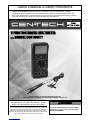
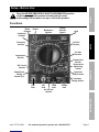
CEN-TECH CEN-TECH 37772 Digital Multimeter is a versatile tool designed to measure voltage, current, resistance, capacitance, frequency, temperature, and test diodes and transistors. It features a large LCD display, a rotary switch for selecting functions and ranges, a push-button for holding data, and overload protection. With its various measurement capabilities and safety features, this multimeter is a valuable tool for electricians, technicians, and hobbyists.
CEN-TECH CEN-TECH 37772 Digital Multimeter is a versatile tool designed to measure voltage, current, resistance, capacitance, frequency, temperature, and test diodes and transistors. It features a large LCD display, a rotary switch for selecting functions and ranges, a push-button for holding data, and overload protection. With its various measurement capabilities and safety features, this multimeter is a valuable tool for electricians, technicians, and hobbyists.


-
 1
1
-
 2
2
-
 3
3
-
 4
4
-
 5
5
-
 6
6
-
 7
7
-
 8
8
-
 9
9
-
 10
10
-
 11
11
-
 12
12


CEN-TECH CEN-TECH 37772 Digital Multimeter User manual
- Category
- Multimeters
- Type
- User manual
CEN-TECH CEN-TECH 37772 Digital Multimeter is a versatile tool designed to measure voltage, current, resistance, capacitance, frequency, temperature, and test diodes and transistors. It features a large LCD display, a rotary switch for selecting functions and ranges, a push-button for holding data, and overload protection. With its various measurement capabilities and safety features, this multimeter is a valuable tool for electricians, technicians, and hobbyists.
Ask a question and I''ll find the answer in the document
Finding information in a document is now easier with AI

