SONY CDX-R3300/R3300S/R3000 (GB,ES,CT) 3-261-846-21 (1)
SONY CDX-R3300/R3300S/R3000 (GB,ES,CT) 3-261-846-21 (1)
182 mm
53 mm
Precautions
•Choose the installation location carefully so
that the unit will not interfere with normal
driving operations.
•Avoid installing the unit in areas subject to
dust, dirt, excessive vibration, or high
temperatures, such as in direct sunlight or
near heater ducts.
•Use only the supplied mounting hardware for
a safe and secure installation.
Mounting angle adjustment
Adjust the mounting angle to less than 45°.
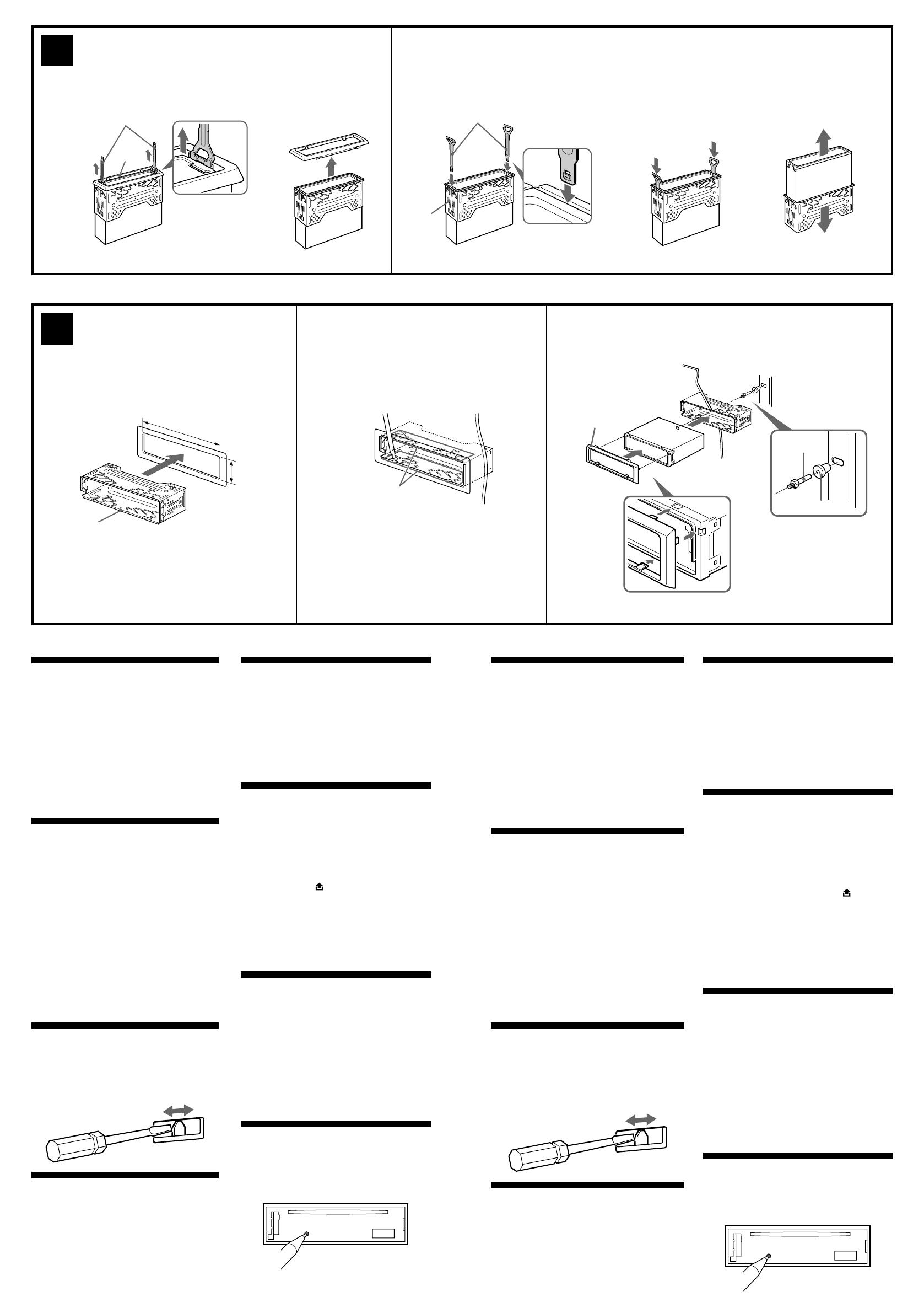
Removing the protection collar
and the bracket (4)
Before installing the unit, remove the
protection collar 5 and the bracket 1 from
the unit.
1 Remove the protection collar 5.
1 Engage the release keys 6 together with
the protection collar 5.
2 Pull out the release keys 6 to remove the
protection collar 5.
2 Remove the bracket 1.
1 Insert both release keys 6 together
between the unit and the bracket 1 until
they click.
2 Pull down the bracket 1, then pull up
the unit to separate.
Frequency select switch
The AM (FM) tuning interval is factory-set to the 9
k (50 k) position. If the frequency allocation system
of your country is based on 10 kHz (200 kHz)
interval, set the switch on the bottom of the unit to
the 10 k (200 k) position before making connections.
Mounting example (5)
Installation in the dashboard
Notes
• Bend these claws outwards for a tight fit, if
necessary (5-2).
• Make sure that the 4 catches on the protection
collar 5 are properly engaged in the slots of the
unit (5-3).
Mounting the unit in a Japanese
car (6)
You may not be able to install this unit in some
makes of Japanese cars. In such a case, consult
your Sony dealer.
Note
To prevent malfunction, install only with the
supplied screws 4.
How to detach and attach the
front panel (7)
Before installing the unit, detach the front
panel.
7-A To detach
Before detaching the front panel, be sure to
press (OFF). Press , then pull it off towards
you.
7-B To attach
Attach part A of the front panel to part B of the
unit as illustrated and push the left side into
position until it clicks.
Warning when installing in a car
without ACC (accessory)
position on the ignition key
switch
After turning off the ignition, be sure to
press and hold (OFF) on the unit until the
display disappears.
Otherwise, the display does not turn off and this
causes battery drain.
RESET button
When the installation and connections are
completed, be sure to press the RESET button
with a ballpoint pen, etc., after detaching the
front panel.
4
1 23
5
1
1
Dashboard
Salpicadero
5
1
2
5
6
6
c
c
c
1
Face the hook inwards.
El gancho debe
encontrarse en la parte
interior.
Claws
Pestañas
Orient the release key
correctly.
Oriente la llave de
liberación en la
dirección correcta.
Precauciones
•Elija cuidadosamente el lugar de montaje de
forma que la unidad no interfiera las funciones
normales de conducción.
•Evite instalar la unidad donde pueda quedar
sometida a altas temperaturas, como a la luz
solar directa o a conductos de calefacción, o a
polvo, suciedad o vibraciones excesivas.
•Para realizar una instalación segura y firme,
utilice solamente las herramientas de montaje
suministrada.
Ajuste del ángulo de montaje
Ajuste el ángulo de montaje a menos de 45°.
Extracción del marco de
protección y del soporte (4)
Antes de instalar la unidad, retire el marco de
protección 5 y el soporte 1 de la misma.
1 Retire el marco de protección 5.
1 Una las llaves de liberación 6 al marco de
protección 5.
2 Retire la llave de liberación 6 para extraer
el marco de protección 5.
2 Retire el soporte 1.
1 Inserte ambas llaves de liberación 6 entre
la unidad y el soporte 1 hasta que encajen.
2 Presione el soporte 1 y, a continuación,
levante la unidad para separar ambos
elementos.
Selector de frecuencia
El intervalo de sintonía de AM (FM) ha sido ajustado
en fábrica a la posición 9 k (50 k). Si el sistema de
asignación de frecuencias de su país se basa en el
intervalo de 10 kHz (200 kHz), ponga este selector,
situado en la base de la unidad, en la posición 10 k
(200 k) antes de realizar las conexiones.
Ejemplo de montaje (5)
Instalación en el salpicadero
Notas
• Si es necesario, doble estas pestañas hacia fuera
para que encaje firmemente (5-2).
• Compruebe que los 4 enganches del marco de
protección 5 estén bien fijados en las ranuras de la
unidad (5-3).
Montaje de la unidad en un
automóvil japonés (6)
No podrá instalar esta unidad en algunos
automóviles japoneses. En tal caso, consulte a su
proveedor Sony.
Nota
Para evitar que se produzcan fallos, realice la
instalación solamente con los tornillos suministrados
4.
Forma de extraer e instalar el
panel frontal (7)
Antes de instalar la unidad, extraiga el panel
frontal.
7-A Para extraerlo
Antes de extraer el panel frontal, asegúrese de
presionar (OFF). Después presione y tire de
él hacia usted.
7-B Para instalarlo
Coloque el orificio A del panel frontal en el eje
B de la unidad, como se muestra en la
ilustración, y después presione la parte
izquierda.
Advertencia sobre la instalación
en un automóvil que no
disponga de posición ACC
(accesorio) en el interruptor de
la llave de encendido
Tras apagar el motor, asegúrese de
mantener presionado (OFF) hasta que
desaparezca la indicación.
De lo contrario, la indicación no se apagará y la
batería se descargará.
Botón RESET
Cuando finalice la instalación y las conexiones,
asegúrese de pulsar el botón RESET con un
bolígrafo, etc.
Fire wall
Cortafuegos
2
3

