Page is loading ...

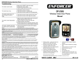
Motion Entry Alert
PI
CZN2
MI_RC
-
135Q_160123.docx
SECO-LARM
®
U.S.A., Inc.
16842 Millikan Avenue, Irvine, CA 92606
Website: www.seco
-
larm.com
Phone: (949) 261
-
2999 | (800) 662
-
0800
Email: sales@seco
-
larm.com
Installation and Important Notes:
1. Using a small screwdriver, remove the battery covers from the sensor and receiver.
2. Install the correct batteries (Sensor – 3 AAA batteries, Receiver – 3 C-cell batteries, not included) for the sensor
and then the receiver using correct polarity as indicated, but do not turn the receiver on at this time. Wait 30
seconds for the sensor to power up. Replace battery covers. Note that receiver can be powered by a 6VDC 2.1mm
power adapter (not included).
3. The sensor and receiver must first be paired before use. To pair the units, turn on the receiver and trigger the sensor with any motion until you hear an
audible and/or visible alert from the receiver to indicate that pairing has been successful. If pairing is not completed within 30 seconds, make sure that both
units' batteries are fresh and that the two units are within range, turn off the receiver, wait a few seconds, and turn on to try pairing again. Note: Each time the
receiver is turned off, the units must again be paired when turned on by triggering the sensor within 30 seconds of turning on the receiver.
4. Determine the location of sensor and receiver units, ensure that the receiver is turned on and paired (see above), and temporarily place them at their
intended location. Turn the receiver's switch to "High" and wait up to 30 seconds for two short beeps to sound, indicating that the receiver is ready. Test the
reception by triggering the sensor. If the receiver does not signal an alert, try changing the position of either unit until a consistent alert trigger is received.
5. Using screws provided, mount the sensor on a flat surface at least 3 feet (1m) above ground level and such that the sensor is facing the area to be
monitored. Note that the sensor detects heat and as such must not face a heat source such as heating vents, strong lights, or direct sunlight and should not
be blocked by other objects or projections. Test to ensure that the sensor is able to detect movement in the intended area to be monitored and readjust
mounting location if needed.
6. Using the screws provided, mount the receiver on a flat vertical surface or place on a horizontal surface. Note that the receiver is not weather-proof and is
meant for indoor use.
Operation:
1. Turn on the power to the receiver and pair it to the sensor as described above. The receiver power switch has four positions:
a. High – A louder alert (approximately 92dB ±5dB) will sound and the LED will flash when sensor is triggered
b. Low – A quieter alert (approximately 80dB ±5dB) will sound and the LED will flash when sensor is triggered
c. Silent – Only the LED will flash when sensor is triggered
d. Off – Unit switched off
2. The receiver LEDs will flash to indicate a low battery. The intrusion LED on the sensor will begin to flash twice every 2 seconds to indicate low battery. Monito
r
these indicators regularly and replace batteries when low. If units will not be used for an extended period, remove batteries to avoid potential damage from
battery leakage.
RC-135Q
Specifications:
Frequency
433.92MHz
Power
Receiver
1.5VDC C
-
cell batteries x3 (not included) or
500mA@6VDC power adapter (not included)
2
Sensor
1.5VDC AAA batteries x 3 (not included)
Low battery
indicators
LEDs flash on sensor and receiver
Material
ABS plastic, white
Sound level (receiver)
92dB or 80dB@1ft. (±5dB) or silent (switchable)
LED indicators (receiver)
3 LEDs flash when sensor activated
PIR Sensor range
26ft (8m) at 40° angle at 3ft
(1m) height
Transmission range
1
Up to 390ft (120m)
IP rating (sensor)
IP44
Temperature
-
4~113°F (
-
20~45°C)
Dimensions
Receiver
5
1
/
8
” x 3
13
/
16
” x 1
5
/
8
” (130x96x42mm)
Sensor
4
3
/
16
” x 3” x 1
7
/
8
” (106x76x48mm)
Weight
Receiver
5
-
oz (125g)
Sensor
3
-
oz
(90g)
1
Transmission range between sensor and receiver will vary depending on installation
and operating environment
2
Use 2.1mm
Parts List:
1x
Receiver
1x
Sensor
3x
Mounting screws
3x
Plastic wall anchors
W
ARRANTY:
This
SEC0
-
LARM product is warranted against defects and workmanship while used in
normal service for 1 (one) year from the date of sale to the original customer.
This device complies with part 15 of the FCC rules.
Operation is subject to the following two conditions:
(1) this device may not cause interference, and (2) this device must accept any interference received,
including interference that may cause undesired operation. FCC ID: K4E135Q
/