Kobalt K7045V User manual

Category
Air compressors
Type
User manual

This manual is also suitable for

Air Compressor
Manual
For Kobalt Models
K7580V2
Stationary
For questions concerning this air compressor,
please call: 1-866-242-4298.
Printed In USA
Stationary Compressor Limited Warranty
Lowe’s Kobalt Models K7045V, K7060HFV & K7580V2
Warranty
This warranty of the Lowe’s Kobalt Stationary Single-Stage Models K7045V and K7060HFV, and Stationary Two-Stage Model K7580V2
(hereinafter the “Kobalt Product”) extends to the original user of the Kobalt product.
Warranty Duration
This Kobalt Product is warranted to the original purchaser from the original purchase date for three (3) years subject to the Warranty Coverage
described herein.
Warranty Coverage
This Kobalt Product is warranted by Abac/American IMC, Inc. USA (referred to hereinafter as “Abac”), 1623 Cedar Line Drive, Rock Hill, SC
29730 to be free from defects in materiel and workmanship.
This warranty is void if: defects in materials or workmanship or damages result from repairs or alterations which have been made or attempted
by others or the unauthorized use of nonconforming parts; the damage is due to normal wear, damage is due to abuse (including overloading
of the Kobalt Product beyond capacity), improper maintenance, neglect or accident; or the damage is due to the use of the Kobalt Product
after partial failure or use with improper accessories or unauthorized repair or alteration. If Kobalt Models K7045V and K7060HFV are used for
commercial or industrial purposes the warranty will apply for ninety (90) days from the date of purchase. Kobalt Model K7580V2 is not limited
to a ninety (90) day warranty when used in commercial or industrial applications.
In addition this warranty does not cover
; nor include any other Kobalt product, including:
· Kobalt product sold as reconditioned or used as rental equipment.
· Pre-delivery service such as assembly, oil or lubricants and adjustments.
· Kobalt products that have become damaged or inoperative because of ordinary wear, misuse (an air compressor that pumps air
more than the recommended duty cycle during a one hour period may be considered misuse), cold, heat, rain, excessive humidity,
freeze damage, use of improper lubricants, negligence, accident, failure to operate the product in accordance with the instructions
provided in the Owners Manual(s) supplied with the product.
· Repair and transportation costs of merchandise determined not to be defective.
· Costs associated with assembly, required lubricants, adjustments or other installation and start-up costs.
· Normal adjustments and expendable parts or accessories supplied with the product which are expected to become inoperative or
unusable after a reasonable period of use, including but not limited to belts, pressure switches, rubber isolation pads, gaskets and
intake air filters.
· Products sold by Abac under the Kobalt Brand which have been manufactured by and are identified as the product of another
company, such as electric motors. That product manufacturer’s warranty, if any, will apply.
· Any component damaged in shipment or any failure caused by installing or operating the compressor under conditions not in
compliance with the installation and operating guidelines.
· Pump or valve failure caused by rain, excessive humidity or corrosive environments and/or by using oil not specified, or by any oil
contamination, or by failure to follow proper oil maintenance guidelines.
· Ring wear from inadequate filter maintenance.
· Cosmetic defects that do not interfere with compressor functionality.
· Rusted tanks, including but not limited to rust due to improper drainage.
· Electric motors and check valves after the first year of ownership.
· Drain valves.
· Damage due to improper wiring.
· Other items not listed but considered to be general wear parts.
Warranty Performance
DURING THE ABOVE DESCRIBED WARRANTY PERIODS SHOULD YOUR KOBALT PRODUCT EXHIBIT A DEFECT IN MATERIALS OR
WORKMANSHIP, SUCH DEFECT WILL BE REPAIRED WHEN THE COMPLETE KOBALT PRODUCT IS SCHEDULED FOR REPAIR BY A
KOBALT AUTHORIZED AIR COMPRESSOR
SERVICE CENTER. Service will be scheduled in accordance to the normal work flow and
business hours at the service center location and the availability of replacement parts. All decisions of “Abac” with regard to this limited
warranty shall be final.
Warranty Disclaimer
NO WARRANTY, ORAL OR WRITTEN, OTHER THAN THE ABOVE WARRANTY IS MADE WITH REGARD TO THIS KOBALT PRODUCT.
ANY IMPLIED WARRANTIES OF “ABAC” REGARDING THIS KOBALT PRODUCT INCLUDING BUT NOT LIMITED TO, THE IMPLIED
WARRANTIES OF MERCHANTABILITY AND FITNESS FOR A PARTICULAR PURPOSE, ARE LIMITED IN DURATION TO THE
WARRANTY PERIODS DESCRIBED ABOVE. “ABAC” SHALL NOT BE LIABLE FOR LOSS OF USE OF THIS PRODUCT OR OTHER
INCIDENTAL OR CONSEQUENTIAL COSTS, EXPENSES, OR DAMAGES INCURRED BY THE PURCHASER.
Limitations of Warranty Disclaimers
Some states do not allow limitations on how long an implied warranty lasts, so the above limitations may not apply to you.
Some states do not allow the exclusion or limitation of incidental or consequential damages, so the above limitation or exclusion may not apply
to you.
Abac/American IMC, Inc. “ABAC” Authorized Service Centers for KOBALT Product
Stationary Air Compressor service under this warranty is available on these Kobalt Product models by contacting us at 1-866-242-4298 for a
service center nearest you to schedule on-site repair.
Rev. 0306
K7045V
K7060HFV
TABLE OF CONTENTS
PAGE
1 Safety Guidelines - Definitions
Before Using the Air Compressor
2 When Installing or Moving the Compressor
Before Each Use
3 Follow Safety Precautions for Electrical Connection
Plan Ahead to Protect Your Eyes, Hands, Face & Ears
When Operating
4 Spraying Precautions
Perform These Maintenance Operations
5 Warning Labels
Glossary
6 Wiring
Starting the Compressor
7-8 Troubleshooting
9-13 Parts
14 Warranty Statement
13
Illustration
Number Description Quantity Part Number
1. Crankcase 1 5961101
2. Cylinder 1 5930001
3. Head 1 5961405
4. Crankshaft 1 5961200
5. Crankcase Bottom 1 5961301
6. Valve Assembly 1 5940051
7. Conrod Insert (Half Bearing) 4 9013013
8. Conrod 2 5011101
9. Conrod Nut 4 9128234
10. HP Piston 1 5021100
11. LP Piston 1 5922100
12. HP Wrist Pin 1 5021200
13. LP Wrist Pin 1 5922200
14. Circlip 4 9140050
15. HP Step Ring 1 9020014
16. HP Compression Ring 1 9020044
17. HP Oil Ring 2 9020074
18. LP Step Ring 1 9020035
19. LP Compression Ring 1 9020047
20. LP Oil Ring 1 9020065
21. Air Filter Assembly 1 5281000
22. Air Filter Element 1 5281100
23. Bearing Housing (NDS) 1 5061690
24. Bearing Housing (DS) 1 5061590
25. Intercooler Tube 1 5962020
26. Flywheel 1 3600101
27. Main Bearing (6206) 2 9170020
28. Oil Sight Glass 1 9022003
29. Oil Fill Plug 1 9024011
30. Oil Seal 1 9163020
31. Flywheel Bolt 1 9110024
32. Flywheel Washer 1 9004009
33. Crankcase Bottom Gasket 1 5950101
34. Crankcase Gasket 1 5950201
35. Cylinder Gasket 1 5950300
36. Valve Plate Gasket 1 5940301
37. Head Gasket 1 5050400
38. Bearing Housing Gasket 2 5050500
39. Intercooler Gasket 1 5950600
40. Safety Valve (1/4 in 65 psi) 1 9049064
41. Head Bolt 6 9101756
42. Bearing Housing Bolt 8 9101144
43. Cylinder Bolt 6 9101324
44. Crankcase Btm. Bolt 12 9114262
45. Intercooler Bolt 3 9101154
46. Oil Drain Plug 1 9101154
47. Inlet Filter Bolt 2 9101524
48. Aftercooler Gasket 1 5070200
49. Aftercooler 1 5070101
50. Safety Valve (1/4 in 217 psi) 1 9049032
Kits
Gasket Kit 53N0056 HP Ring Kit 8227093
HP Running Gear Kit 8226502 LP Ring Kit 8227092
LP Running Gear Kit 8226503
B5900 Two Stage Compressor Pump
46a. Oil Drain Tube 1 9053853
WARNING
Safety is a combination of common sense, staying alert and knowing how your compressor works.
Read this manual to understand this compressor.
CAUTION
DANGER
SAFETY GUIDELINES - DEFINITIONS
means if safety information is not followed someone will be seriously injured or killed
means if safety information is not followed someone may be seriously injured or killed
means if safety information is not followed someone could be seriously injured or killed
IMPORTANT SAFETY INSTRUCTIONS
Save these instructions
Before using the air compressor
Improper operation or maintenance of this product could result in serious injury and property
damage. Read and understand all warnings and operation instructions before using this compressor.
Air compressors are utilized in a variety of air
system applications. Because air compressors
and other components (hoses, connectors, air
tools, spray guns, etc.) make up a high pressure
pumping system, the following safety pre-
cautions should be observed at all times.
Only persons familiar with these rules of
safe operation should use the air
compressor.
1. Read the instruction manual carefully before
attempting to assemble, disassemble or
operate your system. Be thoroughly familiar
with the controls and the proper use of the
equipment.
2. Review and understand all safety instructions
and operating procedures in this manual.
3. Review the maintenance methods for this
compressor (See “Maintaining Your
Compressor” section).
Things you should know Inspect your work area
1. Keep work area clean.
2. Cluttered areas and benches invite accidents.
Floors must not be slippery from wax or dust.
1. To reduce the risk of injury from accidental
starting, turn switch off and disconnect the
power before checking it.
2. If any part is missing, bent or broken in any
way, or any electrical part does not work prop-
erly, keep the compressor off and disconnected.
3. Check hoses for weak or worn condition
before each use, making certain all connections
are secure. Do Not use if defect is found.
Do not operate compressor if damaged during
shipping, handling or use. Damage may result
in bursting and cause injury or property damage.
This compressor is Not designed for and should
not be used in breathing air applications.
Inspect your compressor
WARNING
Page 1
DANGER
Page 12
01
02
03
04
05
06
07
08
09
10
11
12
13
14
15
16
17
18
19
20
21
22
23
24
25
26
27
28
29
30
32
31
33
34
35
36
37
38
39
40
41
42
43
44
45
46
47
48
49
50
B5900 Two Stage Compressor Pump
46a
When installing or moving the compressor
This compressor is extremely top heavy. The
compressor must be bolted to the floor with
vibration pads before operating to prevent
equipment damage, injury or death. Do Not
tighten bolts completely as this may
cause stress to the tank welds.
To reduce the risk of a dangerous
environment
1. Keep work area well lit.
2. Operate compressor in a well-ventilated
area free from flammable liquids and vapors.
3. Operate compressor in a ventilated area so
that compressor may be properly cooled and
the surrounding air temperature will not be
more than 100°F.
4. Never use a compressor in a wet
environment.
5. Protect material lines and air lines from
damage or puncture. Keep hose and
wires away from sharp objects, chemical
spills, oil, solvents and wet floors.
Do Not secure compressor with toggle bolts
into drywall. Drywall sheeting or plaster will not
support the weight of the compressor.
WARNING
Page 2
6. A minimum clearance of 18 inches between
the compressor and a wall is required
because objects could obstruct airflow.
7. The compressor should be located where it can
be directly wired to a circuit breaker. The
compressor should be wired by a qualified
electrician.
8. Never store flammable liquids or gases in
the vicinity of an operating compressor.
9. Do Not locate the compressor air inlet near
steam, paint spray, sandblasting areas or
any other source of contamination. The
debris could damage the motor and pump.
Never use plastic (PVC) pipe for compressed
air. Serious injury or death could result.
Never use the shipping skid for mounting the
compressor.
This compressor is not intended for outdoor
installation.
Never install a shut off valve between the compres-
sor pump and tank. Personal injury and/or
equipment damage could occur.
WARNING
CAUTION
NOTICE
WARNING
WARNING
Before each use
1. Keep work area clean. Cluttered areas and
benches invite accidents.
2. The floor must not be slippery from wax or
dust.
1. To reduce the risk of injury from accidental
starting, turn the switch off and disconnect
power.
2. If any part is missing, bent or broken in any
way, or any electrical part does not work
properly, keep the compressor off and dis-
connect power. Do Not use if defect is found.
3. Check hoses for weak or worn condition
before each use, making certain all connect-
ions are secure. Do Not use if a defect is
found.
Inspect your work area Inspect your compressor
ILLUSTRATION PART PART
NUMBER NUMBER DESCRIPTION
01 3660100 Crankcase
02 3630000 Cylinder
03 3860400 Head (NS18S)
3860401 Head (B3800)
04 3660200 Crankshaft
05 3660160 Crankcase Bottom
06 2840050 Valve Assembly
07 1421100 Piston
08 3610100 Conrod
09 9140040 Circlip
10 9020011 Step Ring
11 9020041 Compression Ring
12 9020071 Oil Ring
13 FS008 Filter Assembly (NS18S)
13a 2281000 Filter Assembly (B3800)
16 2060690 Main Bearing Housing (NDS)
17 2060590 Main Bearing Housing (DS)
18 9170030 Main Bearing (6205)
19 9024021 Oil Fill Plug
20 9163010 Oil Seal
21 9110014 Flywheel Bolt
22 9004008 Flywheel Washer
23 3650100 Crankcase Bottom Gasket
24 3650201 Frame Gasket
25 2850300 Cylinder Gasket
26 2850400 Head Gasket
27 2050500 Bearing Housing Gasket
28 3670200 Aftercooler Gasket
29 9101594 Head Bolt
31 9101144 Aftercooler Bolt
32 9101094 Bearing Housing Bolt
33 9107254 Cylinder Bolt
34 9114273 Crankcase Bottom Bolt
Oil Drain Plug35 9101154
36 9022001 Oil Sight Glass
37 3600100 Flywheel
38 3021200 Wrist Pin
39 3670102 Aftercooler
40 FE004 Filter Element (NS18S)
40a 4981100 Filter Element (B3800)
41 FSAD01 Filter Adapter
Gasket Kit 3650055
Page 11
B3800 and NS18S Single Stage Compressor Pumps
Oil Drain Tube35a 9053853
Note: Tank Outlet Size: 1/2” NPT for Models K7045V and K7060HFV
3/4” NPT for Model K7580V2
Follow the safety precautions for electrical connections
Page 3
WARNING
CAUTION
WARNING
Plan ahead to protect your eyes, hands, face and ears
1. Wear safety glasses (meeting ANSI Z87.1 or
in Canada CSA Z94.3-99) and use hearing
protection when operating the unit. Everyday
glasses are not safety glasses.
2. Wear shoes to prevent shock hazards.
3. Tie back long hair.
Keep fingers away from running compressor.
Fast moving and hot parts may cause injury
and/or burns.
1. Follow all local electrical and safety codes,
as well as the National Electric Code (NEC)
and the Occupational Safety and Health
Act (OSHA).
2. Wiring and fuses should follow electrical
codes, current capacity and be properly
grounded.
3. Protect wires from contact with sharp objects.
All electrical connections should be made by
a qualified electrician.
Dress for safety
Be careful when touching the exterior of comp-
ressor, pump, motor and air lines; they may
become hot enough to cause injury.
Never operate the compressor without a
beltguard. The compressor can start auto-
matically without warning. Personal injury or
property damage could occur from contact
with moving parts.
The compressor may be hot even if the unit is
stopped.
Use of a mask or respirator per chemical
manufacturers’ instructions may be neces-
sary if there is a chance of inhaling toxic fumes.
Read mask and respirator instructions care-
fully. Consult a safety expert if you are not
sure about the use of certain masks or
respirators.
Pay attention to your hands
WARNING
CAUTION
WARNING
When operating
1. Do not exceed the pressure rating of any
component of the system.
2. Release pressure within the system slowly
to prevent flying dust and debris.
3. If the equipment starts to abnormally vibrate,
STOP the compressor immediately and
check for the cause.
WARNING
Never change the safety valve or pressure
switch settings. Keep safety valve free from
paint and other accumulations. See compressor
specification decal for maximum operating
pressure. Do not operate with the pressure
switch set higher than the maximum operating
pressure.
Page 10
B3800 and NS18S Single Stage Compressor Pumps
34
35
23
33
01
19
16
24
02
25
39
06
40
41
29
03
26
31
28
13
10
11
12
07
38
09
04
27
18
32
08
20
05
17
22
21
37
36
Filter for NS18S
Filter for B3800
40
a
13
a
35a
Spraying precautions
Page 4
Perform these maintenance operations
1. Do Not spray in the vicinity of open flames
or other places where a spark can cause
ignition. Do Not smoke when spraying
paint, insecticides, or other flammable
substances.
1. When spraying with solvents or toxic chemi-
cals, follow the instructions provided by the
chemical manufacturer. Consult a safety
expert if unsure about the use of masks or
respirators.
2. If the material you intend to spray contains
trichloreoethane and methylene chloride, do
not use accessories that contain aluminum or
galvanized materials, as these chemicals can
react with galvanized components causing
corrosion and weakening equipment. Use
stainless steel accessories.
WARNING
Never point a spray gun at yourself or any
other person or animal. Accidental discharge
may result in serious injury.
Reduce the risk of dangerous
environment
WARNING
Extreme caution should be taken when
spraying flammable liquids as the spark from
a motor or pressure switch may cause a fire
or explosion. Ample ventilation must be
provided.
WARNING
Spray in a well ventilated area to keep fumes
from collecting and causing serious injury and
fire hazards.
Be informed about the materials you use
1. Do regular maintenance; keep all nuts, bolts,
and screws tight, to be sure equipment is in
safe working condition.
2. Inspect tank yearly for rust, pin holes or any
other imperfections that could cause it to
become unsafe.
NEVER attempt to repair or modify a tank!
Welding, drilling or any other modification will
weaken the tank resulting in damage from
rupture or explosion. Always replace worn,
cracked or damaged tanks.
3. Clean electrical equipment with an approved
cleaning agent, such as a dry, non-flam-
mable cleaning solvent.
Daily
Check oil level at sight glass.
Drain moisture from tank.
Verify the pressure switch unloader is
working by listening for a brief hissing sound
when the compressor shuts off.
Visually check the compressor for loose parts,
excessive noise or vibration.
WARNING
4. Drain tanks of moisture after each day’s use.
If unit will not be used for awhile, it is best to
leave the drain cock open until such time as it
is to be used. This will allow moisture to
completely drain out and help prevent
corrosion of inside of tank.
5. Always disconnect from power source before
working on or near a motor, or its connected
load. If power disconnect point is out-of-
sight, secure it in the “OFF” position and tag it
to prevent unexpected application of power.
Disconnect power and depressurize system
before servicing air compressor. Slightly open
drain cock after shutting off compressor.
Monthly
(Make sure the main power is off.) Check the belts
for tension. Belts should not move up and down
when the compressor runs and when stopped,
should not have more than ½ in of play when
depressed. Be careful not to over tighten belts
during adjustment.
Remove and check air filter, replace if necessary.
Change oil every 3 months or 300 hours. A
compressor grade non-detergent oil should be
used. (40 wt for K7045V/K7060HFV and 30wt
for K7580V2).
WARNING
Page 9
10
09
08
07
06
05
04
03
02
01
Electric Compressors
IllustrationIllustration Part DescriptionPart Description
Single SSingle S
ttageage Single SSingle Sttageage TTwo Swo Sttageage
NumberNumber K7045VK7045V K7060HFVK7060HFV K7580V2K7580V2
1
Compressor Pump
B3800 NS18S B5900
2 Air Filter 2281000 FS008 5281000
3 Electric Motor MCY1556 M182711 M182703
4 Safety Valve 1400110 1400110 SV25200
5 Pressure Switch PSMDR21130 PSMDR21130 PSMDR21KC1F
6 Tank Gauge 1400111 1400111 1400111
7 Tank Drain FIB02DC FIB02DC FIB02DC
8 Check Valve CV21 CV21 CV21
9 Discharge Tube DT0265 DT031 DT030
10 Belt Guard 833500D BG24163 BG31184
Drive Belt
s BA56 BA54 BA60
Drive Pulley SAK5458 SAK5958 SAK51H
*Part Numbers Subject to Change Without Notice
Shown Here as an Example
Model K7580V2
WIRING
WARNING LABELS
Page 5
Find and read all warning labels found on the air compressor.
GLOSSARY OF TERMS
Air Filter
Porous element contained within a metal or
plastic housing attached to the compressor
cylinder head which removes impurity from the
intake air of the compressor.
Air Tank
Cylindrical component which contains the
compressed air.
Check Valve
Device which prevents compressed air from
flowing back from the air tank to the compres-
sor pump.
Electric Motor
Device which provides the rotational force
necessary to operate the compressor pump.
Pressure Gauge
Device which shows the tank or regulated
pressure of the compressed air.
Pressure Switch
Device which automatically controls the on/off
cycling of the compressor. It stops the
compressor when the cut-off pressure in
the tank is reached and starts the compressor
when the air pressure drops below the cut-in
pressure.
PSI (Pounds per Square Inch)
Measurement of the pressure exerted by the
force of air. The actual psi is measured by a
pressure gauge on the compressor.
Pump
Device which produces the compressed air
with a reciprocating piston contained within a
cylinder.
Safety Valve
Device which prevents air pressure in the air
tank from rising over a predetermined limit.
Thermal Overload Switch
Device, integrated into the electric motor winding,
which automatically “shuts off” the compressor
if the temperature of the electric motor exceeds
a predetermined limit.
1. Replace pressure switch if it does not release
air pressure briefly when unit shuts off.
Do not remove pressure
switch with air pressure in
tank
1. Make sure unit is mounted on a level surface
with vibration pads.
2. Replace belts. Align and tighten properly.
3. Align flywheel and drive pulley.
1. Reduce air demand or use a compressor
with more air capacity.
2. Clean all cooling surfaces of dirt and dust.
3. Install compressor in an area with adequate
cool dry air.
1. Malfunctioning check valve
Overheating
TROUBLESHOOTING GUIDE (Continued)
Pressure switch un-
loader constantly
leaking air
1. Replace check valve if unloader bleeds
constantly.
Do not remove check valve
with air pressure in tank
!
DANGER
Pressure switch not
unloading
1. Malfunctioning pressure
switch
!
DANGER
Excessive vibration
1. Compressor too small for
application
2. Cooling surfaces dirty
3. Improper cooling
1. Improper installation
2. Loose belts
3. Misaligned flywheel or
drive pulley
Page 8
To reduce the risk of electrical hazards, fire
hazards or damage to the compressor, use
proper circuit protection. Your compressor
is wired at the factory for operation using
the voltage shown. Connect the compressor
to a power source with the correct breaker
size.
Adequate wiring and motor protection
should be provided for all stationary
compressors. Wiring used for other
machinery should not be used. A
qualified electrician familiar with local
electrical codes in your area should be
used.
WIRING
ALL ELECTRICAL WIRING SHOULD BE DONE
BY A QUALIFIED ELECTRICIAN
General Information
STARTING THE COMPRESSOR
Prior to actually running the compressor,
check the following items:
Crankcase oil - Make sure the sight glass
shows ½ full or slightly above.
Make sure all rags, tools, oil, etc. are away
from the unit.
Open the air system to free it of any pressure.
Switch the compressor on for a few
revolutions to make sure the rotation is
correct. Correct rotation is clockwise
when facing the sight glass on the pump.
Operate the compressor for a few minutes
unloaded (air system open) then allow the
compressor to pump up. Make sure the
electrical pressure switch properly switches
off the compressor according to the setting
desired. (135 psi for K7045V/K7060HFV
and 175 psi for K7580V2)
Make sure the pressure in the tank does
not exceed its rating. Single stage comp-
ressors should operate at a maximum of
135 psi and two stage compressors should
operate at a maximum of 175 psi. If the
pressure gauge indicates a pressure that
is higher than these maximum pressures,
shut off compressor immediately and call
1-866-242-4298.
K7045V
K7060HFV
K7580V2
Voltage
FLA
Breaker Size
230V / 1 ph 230V / 1 ph
16
23
40 amp30 amp
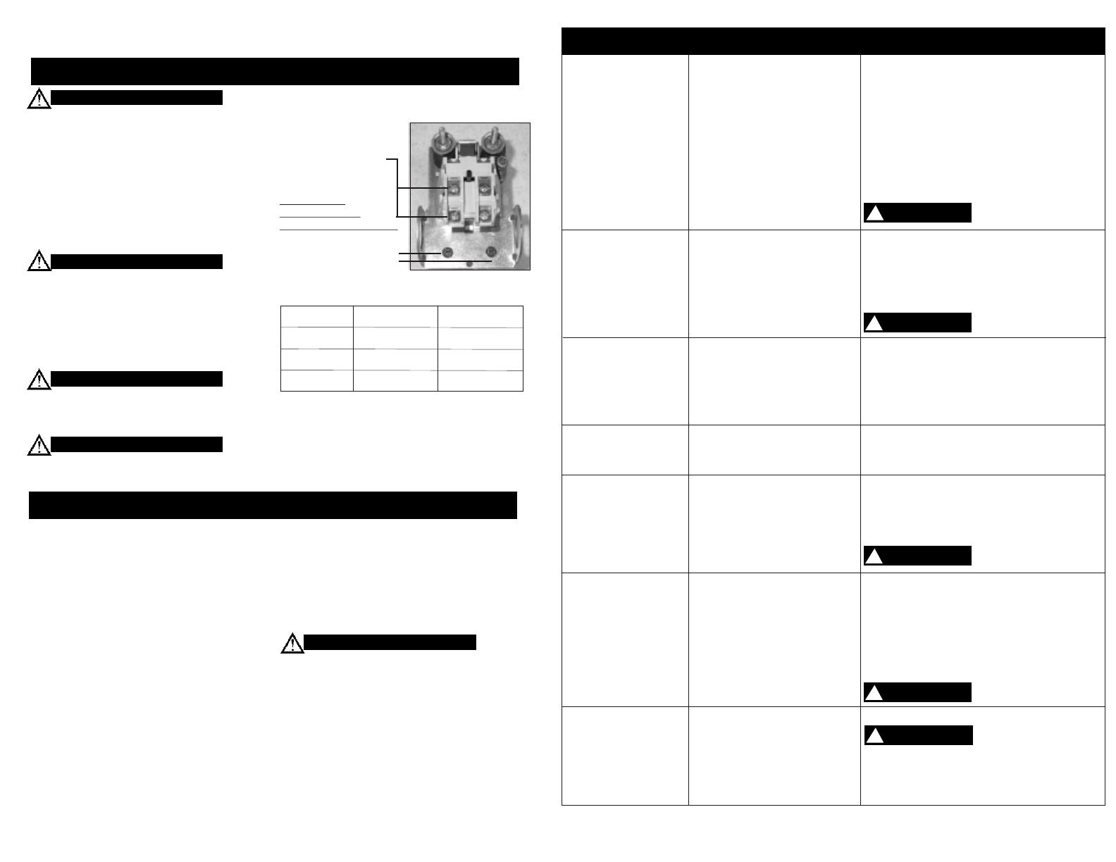
Incoming power should
be connected to the
posts marked (line)
Do Not Make
Connections On
Prewired Posts (Motor)!
Grounding Screw
Electrical connections must be properly
grounded. Ground connections should be
connected at the grounding screw.
The motor is equipped with a manual,
resetable overload device to protect it from
overheating. In the event the compressor will
not run and power is properly connected and
on, press the motor overload reset button
located on the non drive end of the motor.
Overheating, short circuiting and fire damage
will result from inadequate wiring.
WARNING
WARNING
WARNING
CAUTION
WIRING
STARTING THE COMPRESSOR
CAUTION
Page 6
!
DANGER
Low discharge pressure
1. Reduce air demand or use a compressor
with more air capacity.
2. Listen for air leaks. Apply a soap solution
to all fittings and connections. Bubbles
will form at points of leakage. Tighten
or replace fittings or connections.
3. Clean or replace air filter.
4. Replace necessary gaskets.
5. Remove head and inspect for broken or
misaligned valves. Replace valves, if
necessary.
Install a new head gasket
each time head is removed
1. Tighten drive pulley or flywheel bolt.
2. Check for proper oil level. Low or dirty
oil may cause bearing damage.
3. Replace connecting rod and/or connecting
rod bearings.
4. Replace check valve.
Do not remove check valve
with air pressure in tank
1. Replace with new piston rings.
2. Clean or replace air filter.
3. Drain oil to proper oil level.
4. Use a quality non-detergent 30 or 40wt
oil specified for each model (Page 4).
1. Drain tank at least once per day.
2. Add an inline filter to reduce moisture in
in the air line.
1. Check voltage with volt meter across both
legs of incoming power. Check reset button
on motor.
2. Repair or replace pressure switch.
3. Replace check valve or pressure switch.
Do not remove check valve
with air pressure in tank
1. Make sure the breaker is sized properly.
See page 6 in this manual.
2. Check voltage with volt meter across both
legs of incoming power.
3. Replace motor.
4. Check all electrical connections.
5. Adjust or replace pressure switch.
6. Replace check valve.
Do not remove check valve
with air pressure in tank
1. Replace check valve.
Do not remove check valve
with air pressure in tank
2. Tighten or replace fittings or connections.
3. Replace tank. Do not attempt to repair tank.
1. Compressor too small for
application
2. Air leaks
3. Restricted intake air
4. Blown gasket(s)
5. Broken or misaligned valves
!
DANGER
!
DANGER
!
DANGER
1. Loose drive pulley or flywheel
2. Low on oil
3. Worn connecting rod or
connecting rod bearing
4. Noisy check valve
1. Worn piston rings
2. Restricted intake air
3. Too much oil in compressor
4. Incorrect oil viscosity
1. Normal. Amount of water will
increase as humidity in the
air increases.
1. Low voltage
2. Malfunctioning pressure switch
3. Malfunctioning check valve
1. Incorrect breaker size
2. Low voltage
3. Malfunctioning motor
4. Loose electrical connections
5. Malfunctioning pressure switch
6. Malfunctioning check valve
Tank does not hold
pressure when not
running and shut off
valve is closed
Breaker or reset
repeatedly trips
Will not run or motor
hums
Water in tank and/or
discharge line
Excessive oil carryover
Excessive noise
“knocking”
TROUBLESHOOTING GUIDE
1. Malfunctioning check valve
2. Loose fittings or connections
3. Crack or pin hole in tank
Page 7
CAUTION
!
  • Page 1 1
  • Page 2 2
  • Page 3 3
  • Page 4 4
  • Page 5 5
  • Page 6 6
  • Page 7 7
  • Page 8 8

Kobalt K7045V User manual

Category
Air compressors
Type
User manual
This manual is also suitable for

Ask a question and I''ll find the answer in the document

Finding information in a document is now easier with AI